Archive for the ‘Tactical Ventilation’ Category

Influence of Ventilation in Residential Structures: Tactical Implications Part 5

Thursday, September 8th, 2011

The fifth tactical implication identified in the Underwriters Laboratories study of the Impact of Ventilation on Fire Behavior in Legacy and Contemporary Residential Construction (Kerber, 2011) is described as failure of the smoke layer to lift following horizontal natural ventilation and smoke tunneling and rapid air movement in through the front door.

In the experiments conducted by UL, both the single and two story dwellings filled rapidly with smoke with the smoke layer reaching the floor prior to ventilation. This resulted in zero visibility throughout the interior (with the exception of the one bedroom with a closed door). After ventilation, the smoke layer did not lift (as many firefighters might anticipate) as the rapid inward movement of air simply produced a tunnel of clear space just inside the doorway.

Put in the context of the Building, Smoke, Air Track, Heat, and Flame (B-SAHF) fire behavior indicators, these phenomena fit in the categories of smoke and air track. Why did these phenomena occur and what can firefighters infer based on observation of these fire behavior indicators?

Smoke Versus Air Track

There are a number of interrelationships between Smoke and Air Track. However, in the B-SAHF organizing scheme they are considered separately. As we begin to develop or refine the map of Smoke Indicators it is useful to revisit the difference between these two categories in the B-SAHF scheme.

Smoke: What does the smoke look like and where is it coming from? This indicator can be extremely useful in determining the location and extent of the fire. Smoke indicators may be visible on the exterior as well as inside the building. Don’t forget that size-up and dynamic risk assessment must continue after you have made entry!

Air Track: Related to smoke, air track is the movement of both smoke (generally out from the fire area) and air (generally in towards the fire area). Observation of air track starts from the exterior but becomes more critical when making entry. What does the air track look like at the door? Air track continues to be significant when you are working on the interior.

Smoke Indicators

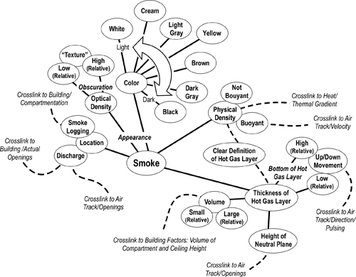
There are a number of smoke characteristics and observations that provide important indications of current and potential fire behavior. These include:

  • Location: Where can you see smoke (exterior and interior)?
  • Optical Density (Thickness): How dense is the smoke? Can you see through it? Does it appear to have texture like velvet (indicating high particulate content)?
  • Color: What color is the smoke? Don’t read too much into this, but consider color in context with the other indicators.
  • Physical Density (Buoyancy): Is the smoke rising, sinking, or staying at the same level?
  • Thickness of the Upper Layer: How thick is the upper layer (distance from the ceiling to the bottom of the hot gas layer)?

As discussed in Reading the Fire: Smoke Indicators Part 2, these indicators can be displayed in a concept map to show greater detail and their interrelationships (Figure 1).

Figure 1. Smoke Indicators Concept Map
Air Track

Air track includes factors related to the movement of smoke out of the compartment or building and the movement of air into the fire. Air track is caused by pressure differentials inside and outside the compartment and by gravity current (differences in density between the hot smoke and cooler air). Air track indicators include velocity, turbulence, direction, and movement of the hot gas layer.

  • Direction: What direction is the smoke and air moving at specific openings? Is it moving in, out, both directions (bi-directional), or is it pulsing in and out?
  • Wind: What is the wind direction and velocity? Wind is a critical indicator as it can mask other smoke and air track indicators as well as serving as a potentially hazardous influence on fire behavior (particularly when the fire is in a ventilation controlled burning regime).
  • Velocity & Flow: High velocity, turbulent smoke discharge is indicative of high temperature. However, it is essential to consider the size of the opening as velocity is determined by the area of the discharge opening and the pressure. Velocity of air is also an important indicator. Under ventilation controlled conditions, rapid intake of air will be followed by a significant increase in heat release rate.

As discussed in Reading the Fire: Air Track Indicators Part 2, these indicators can be displayed in a concept map to show greater detail and their interrelationships (Figure 2).

Figure 2. Air Track Indicators Concept Map

air t
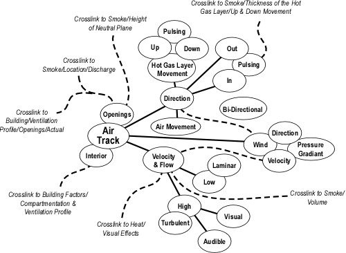
Discharge of smoke at openings and potential openings (Building Factors) is likely the most obvious indicator of air track while lack of smoke discharge may be a less obvious, but equally important sign of inward movement of air. Observation and interpretation of smoke and air movement at openings is an essential part of air track assessment, but it must not stop there. Movement of smoke and air on the interior can also provide important information regarding fire behavior.

An Ongoing Process

Reading the fire is an ongoing process, beginning with reading the buildings in your response area prior to the incident and continuing throughout firefighting operations. It is essential to not only recognize key indicators, but to also note changing conditions. This can be difficult when firefighters and officer are focused on the task at hand.

UL Experiment 13

This experiment examined the impact of horizontal ventilation through the door on Side A and one window as high as possible on Side C near the seat of the fire. The family room was the fire compartment. This room had a high (two-story) ceiling with windows at ground level and the second floor level (see Figure 3).

Figure 3. Two-Story Dwelling
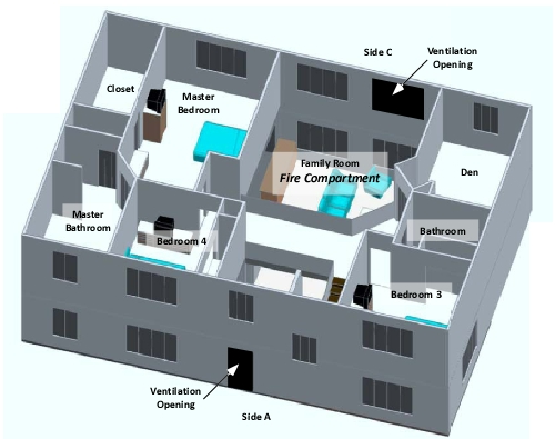
In this experiment, the fire was allowed to progress for 10:00 after ignition, at which point the front door (see Figure 3) was opened to simulate firefighters making entry. Fifteen seconds after the front door was opened (10:15), an upper window in the family room (see Figure 3) was opened. No suppression action was taken until 12:28, at which point a 10 second application of water was made through the window on Side C using a straight stream from a combination nozzle.

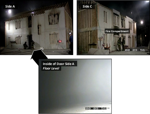
As with all the other experiments in this series fire development followed a consistent path. The fire quickly consumed much of the available oxygen inside the building and became ventilation controlled. At oxygen concentration was reduced, heat release rate and temperature within the building also dropped. Concurrently, smoke and air track indicators visible from the exterior were diminished. Just prior to opening the door on Side A, there was little visible smoke from the structure (see Figure 4).

Figure 4. Experiment 13 at 00:09:56 (Prior to Ventilation)
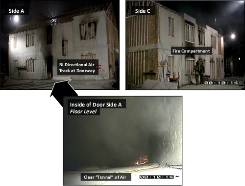
As illustrated in Figure 5, a bi-directional air track was created when the front door was opened. Hot smoke flowed out the upper area of the doorway while air pushed in the bottom creating a tunnel of clear space inside the doorway (but no generalized lifting of the upper layer.

Figure 5. Experiment 13 at 00:10:14 (Door Open)
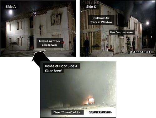
As illustrated in Figure 6, opening the upper level window in the family room resulted in a unidirectional air track flowing from the front door to the upper level window in the family room. No significant exhaust of smoke can be seen at the front door, while a large volume of smoke is exiting the window. However, while the tunneling effect at floor level was more pronounced (visibility extended from the front door to the family room), there was no generalized lifting of the upper layer throughout the remainder of the building.

Figure 6. Experiment 13 at 00:10:21 (Door and Window Open)
With the increased air flow provided by ventilation through the door on Side A and Window at the upper level on Side C, the fire quickly transitioned to a fully developed stage in the family room. The heat release rate (HRR) and smoke production quickly exceeded the limited ventilation provided by these two openings and the air track at the front door returned to bi-directional (smoke out at the upper level and air in at the lower level) as shown in Figure 7.

Figure 7. Experiment 13 at 00:11:22 (Door and Window Open)
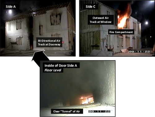
What is the significance of this observation? Movement of smoke out the door (likely the entry point for firefighters entering for fire attack, search, and other interior operations) points to significant potential for flame spread through the upper layer towards this opening. The temperature of the upper layer is hot, but flame temperature is even higher, increasing the radiant heat flux (transfer) to crews working below. Flame spread towards the entry point also has the potential to trap, and injure firefighters working inside.

Gas Velocity and Air Track

A great deal can be learned by examining both the visual indicators illustrated in Figures 4-7 and measurements taken of gas velocity at the front door. During the ventilation experiments conducted by UL, gas velocities were measured at the front door and at the window used for ventilation (see Figure 3). Five bidirectional probes were placed in the doorway at 0.33 m (1’) intervals. Positive values show gas movement out of the building while negative values show inward gas movement. In order to provide a simplified view of gas movement at the doorway, Figure 8 illustrates gas velocity 0.33 m (1’) below the top of the door, 0.33 m (1’) from the bottom of the door, and 0.66 m (2’) above the bottom of the door.

A bidirectional (out at the top and in at the bottom) air track developed at the doorway before the door was opened (see Figure 8) as a result of leakage at this opening. It is interesting to note variations in the velocity of inward movement of air from the exterior of the building, likely a result of changes in combustion as the fire became ventilation controlled. The outward flow at the upper level resulted in visible smoke on the exterior of the building. While not visible, inward movement of air was also occurring (as shown by measurement of gas velocity at lower levels in the doorway.

Creation of the initial ventilation opening by opening the front door created a strong bidirectional air track with smoke pushing out the top of the door while air rapidly moved in the bottom. Had the door remained the only ventilation opening, this bidirectional flow would have been sustained (as it was in all experiments where the door was the only ventilation opening).

Opening the upper window in the family room resulted in a unidirectional flow inward through the doorway. However, this phenomenon was short lived, with the bidirectional flow reoccurring in less than 60 seconds. This change in air track resulted from increased heat release rate as additional air supply was provided to the fire in the family room.

Figure 8. Front Door Velocities
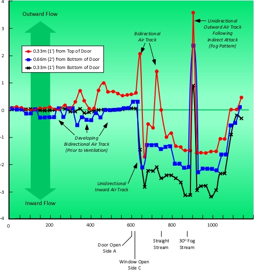
Note: Adapted from Impact of Ventilation on Fire Behavior in Legacy and Contemporary Residential Construction (p. 243), by Stephen Kerber, Northbrook, IL: Underwriters Laboratories, 2011.

While not the central focus of the UL research, these experiments also examined the effects of exterior fire stream application on fire conditions and tenability. Each experiment included a 10 second application with a straight stream and a 10 second application of a 30o fog pattern. Between these two applications, fire growth was allowed to resume for approximately 60 seconds.

The straight stream application resulted in a reduction of temperature in the fire compartment and adjacent compartments (where there was an opening to the family room or hallway) as water applied through the upper window on Side C (ventilation opening) cooled the compartment linings (ceiling and opposite wall) and water deflected off the ceiling dropped onto the burning fuel. As the stream was applied, air track at the door on Side A changed from bidirectional to unidirectional (inward). This is likely due to the reduction of heat release rate achieved by application of water onto the burning fuel with limited steam production.

When the fog pattern was applied, there was also a reduction of temperature in the fire compartment and adjacent compartments (where there was an opening in the family room or hallway) as water was applied through the upper window on Side C (ventilation opening) cooled the upper layer, compartment linings, and water deflected off the ceiling dropped onto the burning fuel. The only interconnected area that showed a brief increase in temperature was the ceiling level in the dining room. However, lower levels in this room showed an appreciable drop in temperature. Air track at the door on Side A changed from bidirectional to unidirectional (outward) when the fog stream was applied. This effect is likely due to air movement inward at the window on Side C and the larger volume of steam produced on contact with compartment linings as a result of the larger surface area of the fog stream.

The effect of exterior streams will be examined in more detail in a subsequent post.

Important Lessons

The fifth tactical implication identified in the Underwriters Laboratories study of the Impact of Ventilation on Fire Behavior in Legacy and Contemporary Residential Construction (Kerber, 2011) is described as failure of the smoke layer to lift following horizontal natural ventilation and smoke tunneling and rapid air movement in through the front door.

Additional lessons that can be learned from this experiment include:

  • Ventilating horizontally at a high point results in higher flow of both air and smoke.
  • Increased inward air flow results in a rapid increase in heat release rate.
  • The rate of fire growth quickly outpaced the capability of the desired exhaust opening, returning the intended inlet to a bi-directional air track (potentially placing firefighters entering for fire attack or search at risk due to rapid fire spread towards their entry point).

Tactical applications of this information include:

  • Ensure that the attack team is in place with a charged line and ready to (or has already) attack the fire (not simply ready to enter the building) before initiating horizontal ventilation.
  • Cool the upper layer any time that it is above 100o C (212o F) to reduce radiant and convective heat flux and to limit potential for ignition and flaming combustion in the upper layer.

Note that this research project did not examine the impact of gas cooling, but examination of the temperatures at the upper levels in this experiment (and others in this series) point to the need to cool hot gases overhead.

What’s Next?

I am on the hunt for videos that will allow readers to apply the tactical implications of the UL study that have been examined to this point in conjunction with the B-SAHF fire behavior indicators. My next post will likely provide an expanded series of exercises in Reading the Fire.

The next tactical implication identified in the UL study (Kerber, 2011) examines the hazards encountered during Vent Enter Search (VES) tactical operations. A subsequent post will examine this tactic in some detail and explore this tactical implication in greater depth.

References

Kerber, S. (2011). Impact of ventilation on fire behavior in legacy and contemporary residential construction. Retrieved July 16, 2011 from http://www.ul.com/global/documents/offerings/industries/buildingmaterials/fireservice/ventilation/DHS%202008%20Grant%20Report%20Final.pdf

Influence of Ventilation in Residential Structures: Tactical Implications Part 4

Sunday, August 14th, 2011

The fourth tactical implication identified in the Underwriters Laboratories study of the Impact of Ventilation on Fire Behavior in Legacy and Contemporary Residential Construction (Kerber, 2011) is that fire attack and (tactical) ventilation must be coordinated. This recommendation has been repeated in National Institute for Occupational Safety and Health (NIOSH) Death in the Line of Duty Reports for many years. In fact, most reports on firefighter fatalities related to rapid fire progression contain this recommendation.

Importance of Coordination

Coordination of (tactical) ventilation and fire attack as a tactical implication is closely related to the first two tactical implications identified in the UL study; potential changes in fire behavior based on stages of fire development, burning regime, and changes in ventilation profile that increase oxygen supplied to the fire.

If air is added to the fire and water is not applied in the appropriate time frame the fire gets larger and the hazards to firefighters increase. Examining the times to untenability provides the best case scenario of how coordinated the attack needs to be. Taking the average time for every experiment from the time of ventilation to the time of the onset of firefighter untenability conditions yields 100 seconds for the one-story house and 200 seconds for the two-story house. In many of the experiments from the onset of firefighter untenability until flashover was less than 10 seconds. These times should be treated as very conservative. If a vent location already exists because the homeowner left a window or door open then the fire is going to respond faster to additional ventilation openings because the temperatures in the house are going to be higher at the time of the additional openings (Kerber, 2011, p. 289-290)

The Impact of Ventilation on Fire Behavior in Legacy and Contemporary Residential Construction Underwriters Laboratories (UL) on-line course and report provide an example of firefighters are at risk when ventilation is performed prior to entry, fire attack is delayed, and other tactical operations such as primary search are initiated.

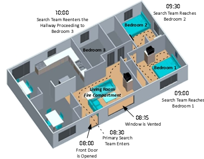
In UL’s hypothetical example, the firefighters make entry into the one-story house, search the living room (fire compartment), the kitchen, and dining room shortly after forcing the door and ventilating a large window in the fire compartment. Consider a somewhat different scenario, with the same fire conditions.

Companies respond to a residential fire with persons reported during the early morning hours. A truck and engine arrive almost simultaneously and while the engine lays a supply line from a nearby hydrant, the truck company forces entry, ventilates a window on Side A, and begins primary search (anticipating that the engine crew will be right behind them to attack the fire). The engine completes a forward lay and begins to stretch an attack line after the search team has made entry.

Figure 1. Timeline and Progression of Primary Search

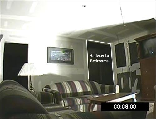
Figure 2. View of the Living Room (Fire Compartment) from the Door on Side A

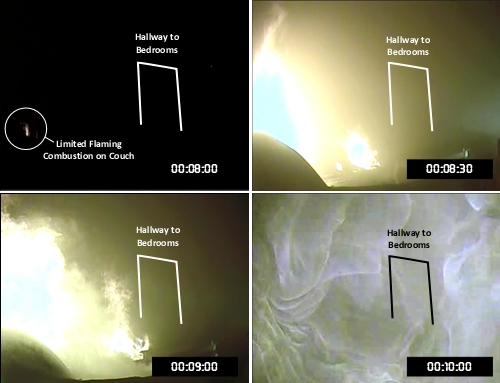
As illustrated in Figure 3, visible flaming combustion when the door is opened at 08:00 is limited to a small flame from the top of the couch just inside the door on Side A. However, in the 30 seconds that it takes for the search team to make entry, flaming combustion has resumed and flames are near or at the ceiling above the couch. The search team may estimate that they have time to complete a quick search of the bedrooms (likely location of the reported persons). However, fire development progresses to untenable conditions within a minute, trapping the crew on Side D of the house.

Figure 3. Fire Progression in the Living Room 00:08:00 to 00:10:00

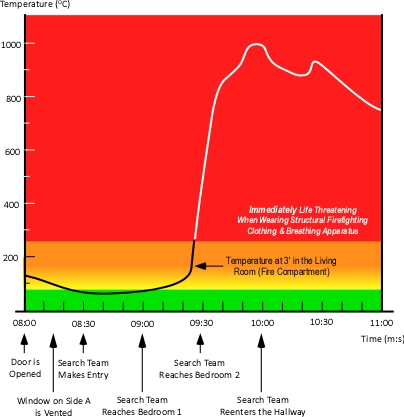
As the search team completes primary search of Bedroom 2 and moves towards Bedroom 3 in the hallway, conditions have deteriorated to an untenable level. Figure 4 illustrates the change in temperature at the 3’ level in the Living Room (fire compartment). Shortly before the search team reached Bedroom 2, fire conditions in the living room began to change dramatically, with temperature at the 3’ level transitioning from ordinary to extreme, quickly becoming untenable in the living room, hallway and adjacent compartments. In addition to this significant change in temperature, flames (with temperatures higher than the gas temperature at the 3’ level) significantly increase radiant heat transfer (flux) to the surface of both fuel packages and firefighters protective equipment.

Figure 4. Temperature at the 3’ Level

Note: Figure 4 illustrates temperature conditions starting eight minutes after ignition. The fire previously progressed through incipient and growth stages before beginning to decay due to lack of ventilation.

Why the Dramatic Change in Conditions?

As discussed in UL Tactical Implications Part 1, Fires in the contemporary environment progress from ignition and incipient stage to growth, but often become ventilation controlled and begin to decay, rather than continuing to grow into a fully developed fire. This ventilation induced decay continues until the ventilation profile changes (e.g., window failure due to fire effects, opening a door for entry or egress, or intentional creation of ventilation openings by firefighters. When ventilation is increased, heat release rate again rises and temperature climbs with the fire potentially transitioning through flashover to the fully developed stage (see Figure 4 and 5).

Figure 5. Fire Development in a Compartment

Captain James Mendoza of the San Jose (CA) Fire Department and CFBT-US Lead Instructor demonstrates the influence of ventilation on fire development using a small scale prop developed by Dr. Stefan Svensson of the Swedish Civil Contingencies Agency.

The prop used in this demonstration is a small, single compartment with a limited ventilation opening on the right side (which in a full size building could be represented by normal building leakage or a compartment opening that is restricted such as a partially open door or window). The front wall of the prop is ceramic glass to permit direct observation of fire conditions within the compartment.

As you watch this demonstration, pay particular attention to how conditions change as the fire develops and then enters the decay stage. In addition, observe how quickly the fire returns to the growth stage and develops conditions that would be untenable after the window is opened at 12:17.

Download Doll’s House Plans (or Doll’s House Plans: Metric) for directions on how to construct a similar small scale prop.

Fire development and changes in conditions following ventilation in this demonstration mirror those seen in the full scale experiments conducted by UL. Increasing ventilation to a ventilation controlled fire, results in increased heat release rate and transition from decay to the growth stage of fire development.

The same phenomena can be observed under fireground conditions in the following video clip of a residential fire in Dolton, Illinois (this is a long video, watch the first several minutes to observe the changes in fire behavior).

It appears that the front door was open at the start of the video clip and the large picture window on Side A was ventilated at approximately 00:47. Fire conditions quickly transition to the growth stage with flames exiting the window and door, causing firefighters on an uncharged hoseline that had been advanced into Floor 1, to quickly withdraw.

As discussed in UL Tactical Implications: Part 1:

  • Fires that have progressed beyond the incipient stage are likely to be ventilation controlled when the fire department arrives.
  • Ventilation controlled fires may be in the growth, decay, or fully developed stage.
  • Regardless of the stage of fire development, when a fire is ventilation controlled, increased ventilation will always result in increased HRR.
  • Firefighters and fire officers must recognize that the ventilation profile can change (e.g., increasing ventilation) as a result of tactical action or fire effects on the building (e.g., window failure).
  • Firefighters and fire officers must anticipate potential changes in fire behavior related to changes in the ventilation profile and ensure that fire attack and ventilation are closely coordinated.

Coordinated Tactical Operations

Understanding how fire behavior can be influenced by changes in ventilation is essential. But how can firefighters put this knowledge to use on the fireground and what exactly does coordination of tactical ventilation and fire attack really mean?

Tactical ventilation can be defined as the planned, systematic, and coordinated removal of hot smoke and fire gases and their replacement with fresh air. Each of the elements of this definition is important to safe and effective tactical operations.

Ventilation (both tactical and unplanned) not only removes hot smoke, but it also introduces fresh air which can have a significant effect on fire behavior.

Tactical ventilation must be planned; these two elements speak to the intentional nature of tactical ventilation. Tactics to change the ventilation profile must be intended to influence the fire environment or fire behavior in some way (e.g., raise the level of the upper layer to increase visibility and tenability). The ventilation plan must also consider the flow path (e.g., vent ahead of, not behind, the attack team; vent in the immediate area of the fire, not at a remote location).

Tactical ventilation must be systematic, exhaust openings should generally be made before inlet openings (particularly when working with positive pressure ventilation or when taking advantage of wind effects).

And as pointed out in the UL Study (Kerber, 2011), tactical ventilation must be coordinated. Coordination of ventilation and other tactical operations requires consideration of sequence and timing:

Sequence: Ventilation may be completed before, during, or after fire attack has been initiated. Sequence will likely depend on the stage of fire development, burning regime, time required to reach the fire.

If the fire is small and staffing is limited, it may be appropriate to control the fire and then effect ventilation (e.g., hydraulic ventilation performed by the attack team). This approach minimizes potential fire growth,

In general, when the fire is ventilation controlled (as those beyond the incipient stage are likely to be), ventilation should not be completed unless the attack line(s) can quickly apply water to the seat of the fire. In a small, single family dwelling this may mean that the attack team is on-air, the line is charged, and the entry door is unlocked or has been forced and is being controlled (held closed). In a larger building, this may mean that the attack line has entered the structure and is in position to move onto the fire floor or into the fire area.

The key questions that must be answered prior to implementing tactical ventilation are:

  1. What influence will these ventilation tactics have on fire behavior?
  2. Are charged and staffed attack line(s) in place?
  3. Will the attack team(s) be able to quickly reach the fire?
  4. How will this impact crews operating on the interior of the building?

Coordination requires clear, direct communication between companies or crews assigned to ventilation, fire attack, and other tactical functions that are or will be taking place inside the building.

Important: While not a tactical implication directly raised by the UL study, another important consideration is the hazard of working without or ahead of the hoseline. While a controversial topic in the US fire service (where truck company personnel generally work on the interior without a hoseline), searching with a hoseline provides a means of protection and a defined exit path. Staffing is another key element of the operational context. If you do not have enough personnel to control the fire and search; in most cases it is likely the best course of action to control the fire and ensure a safer operating environment for search operations.

What’s Next?

The next tactical implication identified in the UL study (Kerber, 2011) examines information that may be obtained by reading the air track at the entry point opening. This implication will be expanded with a broader discussion of air track indicators and how related hazards can be mitigated to improve firefighter safety.

References

Kerber, S. (2011). Impact of ventilation on fire behavior in legacy and contemporary residential construction. Retrieved July 16, 2011 from http://www.ul.com/global/documents/offerings/industries/buildingmaterials/fireservice/ventilation/DHS%202008%20Grant%20Report%20Final.pdf


Note: Figure 4 illustrates temperature conditions starting eight minutes after ignition. The fire previously progressed through incipient and growth stages before beginning to decay due to lack of ventilation.

Why the Dramatic Change in Conditions?

As discussed in UL Tactical Implications Part 1 [LINK], Fires in the contemporary environment progress from ignition and incipient stage to growth, but often become ventilation controlled and begin to decay, rather than continuing to grow into a fully developed fire. This ventilation induced decay continues until the ventilation profile changes (e.g., window failure due to fire effects, opening a door for entry or egress, or intentional creation of ventilation openings by firefighters. When ventilation is increased, heat release rate again rises and temperature climbs with the fire potentially transitioning through flashover to the fully developed stage (see Figure 4 and 5).

Figure 5. Fire Development in a Compartment

Influence of Ventilation in Residential Structures: Tactical Implications Part 2

Saturday, June 18th, 2011

Is making entry with a hoseline for fire attack, ventilation? Is entering through a doorway when conducting search, ventilation? While many firefighters do not think about ventilation when performing these basic fireground tasks, the answer is a resounding yes!

Making Entry is Ventilation

While the Essentials of Firefighting (IFSTA, 2008) defines ventilation as “the systematic removal of heated air, smoke, and fire gases from a burning building and replacing them with cooler air” [emphasis added] (p. 541), the main focus of most ventilation training is on the exhaust opening. In discussing compartment fire development, the 6th Edition of Essentials (IFSTA, 2008) includes a discussion of the concept of fuel and ventilation controlled burning regimes. In addition, the section of the text addressing the positive effects of ventilation such as reducing potential for flashover and backdraft, Essentials (IFSTA, 2008) cautions that increasing ventilation to ventilation limited fires may result in rapid fire progression. However, these concepts were not included in earlier additions and the connection between openings made for the purpose of ventilation and openings made for other reasons is often overlooked.

Ventilation versus Tactical Ventilation

Despite the definitions given in fire service text that describe ventilation in terms of actions taken by firefighters, ventilation is simply the exchange of the atmosphere inside a building with that which is outside. Normal air exchange between the interior and exterior of a building is expressed as the number of complete air exchanges (by volume) per hour and varies depending on the purpose and function of the space. In residential structures, the air in the building is completely exchanged approximately four times per hour. In commercial and industrial buildings this rate may be significantly higher, depending on use. When firefighters arrive to find smoke issuing from a building, ventilation is occurring and when firefighters open a door to make entry, the ventilation profile changes as ventilation has been increased. Remember:

  • If smoke exits the opening (air is entering somewhere else) ventilation is occurring.
  • If air enters the opening (smoke is exiting somewhere else), ventilation is occurring.
  • If smoke exits and air enters the opening ventilation is occurring.

The entry point is a ventilation opening and if the fire is ventilation controlled, any ventilation opening will increase heat release rate (HRR)!

Ventilation Controlled Fires

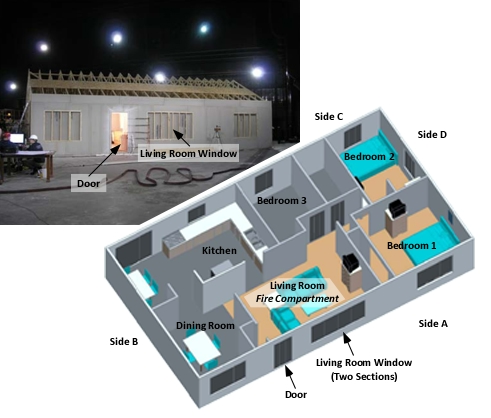
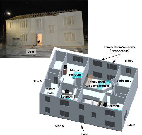
As discussed in Influence of Ventilation in Residential Structures: Tactical Implications Part 1 [LINK], compartment fires that have progressed beyond the incipient stage are likely to be ventilation controlled when the fire department arrives. Firefighters and fire officers must recognize the potential for a rapid increase in HRR when additional atmospheric oxygen is provided to ventilation controlled fires. This is particularly important when considering door entry and door control during fire attack, search, and other interior operations. The Underwriters Laboratories (UL) research project Impact of Ventilation on Fire Behavior in Legacy and Contemporary Residential Construction (Kerber, 2011) examined fire behavior in a small, single-story, wood frame house and a larger, two-story, wood frame house (see Figures 1 & 2) Figure 1. Single-Story Legacy Dwelling

Figure 2. Two-Story Contemporary Dwelling

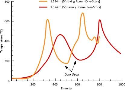
Each of the fires in these experiments occurred in the living room (one-story house) or family room (two-story house). While the fuel load was essentially the same, the family room had a much greater volume as it had a common cathedral ceiling with an atrium just inside the front door. Experiments one and two examined fire behavior in each of these structures with the front door being opened at the simulated time of arrival of the fire department. Figure 3 illustrates the changes in temperature during UL Experiment 1 (Single Story-Door as Vent Opening) and Experiment 2 (Two-Story-Door as Vent Opening). Figure 3. Living/Family Room Temperature Curves-Door as Ventilation Opening

As illustrated in Figure 3, temperature conditions changed dramatically and became untenable shortly after the front door was opened. In the one-story experiment (Experiment 1) temperature:

  • Was 180 °C (360 °F) at ventilation (480 s),
  • Exceeded the firefighter tenability threshold of 260 °C (500 °F) at 550 s
  • Reached 600 °C (1110 °F) at 650 s and transitioned through flashover to a fully developed fire in the living room

In the two-story experiment (Experiment 2) temperature:

  • Was 220 °C (430 °F) at ventilation (600 s)
  • Exceeded the firefighter tenability threshold of 260 °C (500 °F) at 680 s
  • Reached 600 °C (1110 °F) at 780 s and transitioned through flashover to a fully developed fire in the family room

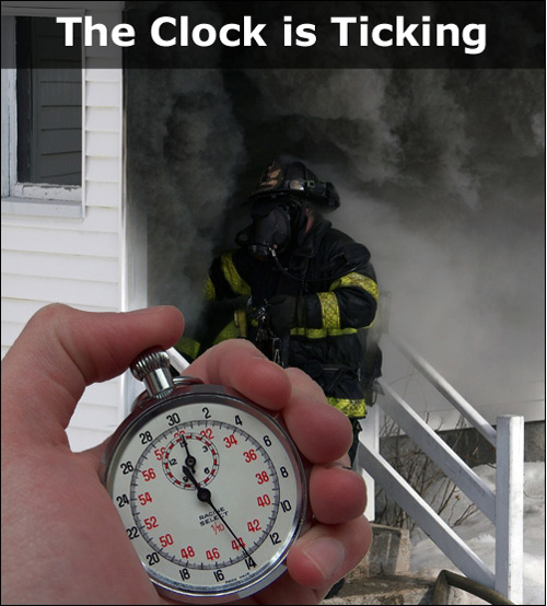
When the door is opened the clock is ticking! HRR will increase and the tenability within the fire compartment and adjacent spaces will quickly deteriorate unless water can be applied to control the fire. Keeping the door closed until ready to make entry delays starting the clock. Closing the door after entry (leaving room for passage of your hoseline) slows fire development and buys valuable time to control the fire environment, locate the fire, and achieve fire control.

Just as in the UL experiments on the influence of ventilation in residential structures, heat release rate will increase and fire conditions can change dramatically when a door is opened for access and entry.

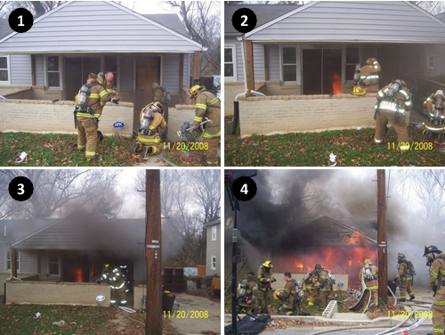
In 2008, two firefighters from the Riverdale Volunteer Fire Department in Prince Georges County Maryland recently were surprised by a flashover in a small, single family dwelling. In the first photo, firefighters from Engine 813 and Truck 807 prepare to make entry. Note that the front door is closed, the glass of the slider and windows are darkened, and smoke can be observed in the lower area of the front porch. Six seconds later it appears that the front door has been opened, flames are visible through the sliding glass door, and the volume of smoke in the area of the porch has increased. However, the smoke is not thick (optically dense). Forty eight seconds later, as the crew from Truck 807 makes entry to perform horizontal ventilation the volume of smoke from the front door increases and thickens (becomes more optically dense).

Figure 4. Ventilation Induced Flashover-Door as a Ventilation Opening

Note: Photos by Probationary Firefighter Tony George, PGFD The crew from Engine 813 experienced a burst hoseline, delaying fire attack. Two minutes after the first photo, and shortly after the crew from Truck 807 made entry, flashover occurred. For additional information on this incident, see Situational Awareness is Critical.

Door Control

The issue of door control presents a similar (and related) paradox as ventilation. Ventilation is performed to improve interior tenability and to support fire control, but when presented with a ventilation controlled fire, increased air supply increases HRR and can result in worsening tenability and potential for extreme fire behavior. Firefighters often chock doors open to provide ease of hoseline deployment and an open egress path, but when the fire is ventilation controlled, this (ventilation) opening starts the clock on increased HRR and rapid fire development. It is useful to consider door control in two phases, door entry procedures and control of the door after entry.

Size-Up: Door entry begins with a focused size-up as you approach the building. Assessment of conditions is not only the incident commander or officer’s job. Each member entering the building should perform a personal size-up and predict likely conditions. When making entry, size-up becomes more closely focused on conditions observed at or near the door and includes an assessment of potential forcible entry requirements as well as B-SAHF (Building-Smoke, Air Track, Heat, and Flame) indicators. If available, a thermal imaging camera (TIC) can be useful, but remember that temperature conditions may be masked by the thermal characteristics of the building. If a thermal imaging camera is not available, application of a small amount of water to the door may indicate temperature and the level of the hot gas layer (water will vaporize on contact with a hot door).

Size-up begins as you exit the apparatus and approach the building, but continues at the door and after you make entry!

At the door, pay close attention to air track and heat (door temperature) indicators as these can provide important clues to conditions immediately inside the building!

Prior to Entry: If the door is open, close it. If it is closed, don’t open it until you are ready. If the door is unlocked, control is generally a simple process (see Nozzle Techniques and Hose Handling: Part 3 for detailed discussion of door entry when the door is unlocked).

If the door is locked and must be forced, this adds an element of complexity to the door entry process. In selecting a forcible entry method, consider that the door must remain intact and on its hinges if you are going to maintain control of the air track at the opening.

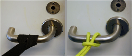
This is fairly easy with outward opening doors. Inward opening doors present a greater challenge. A section of webbing or rope can be used to control an inward door by placing a cinch hitch around the door knob (see Figure 5). As the the door is forced, it can be pulled closed. However, if the door was not locked with a deadbolt, it may re-latch when pulled closed. Figure 5. Door Control with Web or Utility Rope

Figure 5. Door Control with Webbing or Utility Rope

<

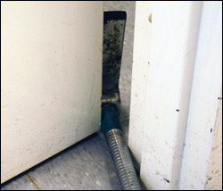
Alternately, a Halligan or hook may be used to capture the door and pull it substantially closed after it is forced (see Figure 6).

Figure 6. Door Control with a Tool

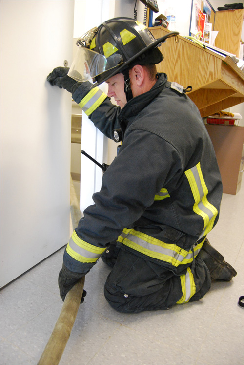
If B-SAHF (Building, Smoke, Air Track, Heat, & Flame) indicators point to hazardous conditions on the other side of the door, forcible entry must be integrated with good door entry procedure to control potential hazards. After Entry: The most effective way to control the door after entry and provide ease of egress is to have a firefighter remain at the opening to control the door and feed hose to the hose team working inside (see Figure 7).

Figure 7. Door Control After Entry

Note: The Firefighter maintaining door control would be wearing complete structural firefighting clothing and breathing apparatus (this is simply an illustration of door control with a hoseline in place)!

Unfortunately, many companies do not have sufficient staff to maintain a nozzle team of two and leave another firefighter at the door. In these cases, it may be possible for the standby firefighters (two-out) to control the door for the crew working inside until additional resources are available.

Nozzle Technique & Hose Handling

Prior posts on nozzle technique and hose handling included a series of drills to develop proficiency in critical skills.

Review these nine drills and then extend your proficiency by integrating forcible entry with good door entry procedure by maintaining control of the door.

Drill 10-Door Entry-Forcing Inward Opening Doors: Many doors (particularly interior and exterior residential) open inward. In this situation forcible entry, door control, and nozzle operation must bee closely coordinated. Practicing these techniques under a variety of conditions (e.g., wall locations, compartment sizes) is critical to developing proficiency.

Drill 11-Door Entry-Forcing Outward Opening Doors: Commercial (and some interior residential doors) open outward. While less complex, Firefighters must develop skill in integration of forcible entry, door control, and nozzle technique in this situation as well.

Hose Handling and Nozzle Technique Drills 11 & 12 Instructional Plan

In both of these drills, focus on maintaining control of the door during forcible entry and limit air intake by keeping the door as closed as possible while passing the hoseline as it is advanced.

References

Kerber, S. (2011). Impact of ventilation on fire behavior in legacy and contemporary residential construction. Retrieved January 20, 2011 http://www.ul.com/global/documents/offerings/industries/buildingmaterials/fireservice/ventilation/DHS%202008%20Grant%20Report%20Final.pdf
International Fire Service Training Association (IFSTA). (2008) Essentials of firefighting (6th ed.). Stillwater, OK: Fire Protection Publications.

Did You Ever Wonder?

Thursday, December 24th, 2009

The ability to read the fire and predict likely fire behavior is a critical skill for both firefighters and fire officers. Previous posts have examined how to use the B-SAHF scheme to recognize critical fire behavior indicators and identify the stage of fire development, burning regime, and potential for extreme fire behavior such as flashover or backdraft. However, there is something missing!

Experience is critical to adapting standard procedures and practices to a complex and dynamic operational environment. However, learning about fire behavior and changes in fire conditions based on fireground observations are a bit like a black box test. Black box testing is a technique for testing computer software in which the internal workings of the item being tested are not known by the tester. This is not entirely true in the case of fire behavior, but there is much that we dont know when assessing conditions on the fireground. How long has the fire been burning? What are the specific characteristics of the fuel? What sort of internal compartmentation is present? What exactly is the ventilation profile? Some of these factors can be determined during fire investigation and it is also possible to determine (with some degree of uncertainty) what influence these factors had on the outcome of the incident. Did you ever wonder how fire behavior would have changed if you had used different tactics? Unfortunately, in real life there are no do overs!

UL Tactical Ventilation Research Project

One of the people who has asked himself the question of what would have changed if different tactics were used is Underwriters Laboratories Fire Protection Engineer Steve Kerber.

Underwriters Laboratories (UL) has received a Firefighter Safety Research and Development Grant from the Department of Homeland Security (DHS). This research project will investigate and analyze the impact of natural horizontal ventilation on fire development and conditions in legacy (older, more highly compartmented) and contemporary (multi-level, open floor plan) residential structures.

Preliminary work has included review of literature related to horizontal ventilation and incidents in which ventilation had a significant influence on firefighter injuries and fatalities. In addition, UL has done preliminary work on the performance of various structural components such as single and multi-pane windows as preliminary input for design of full scale residential fire experiments.

In mid-December 2009, Steve Kerber met with the project advisory panel comprised of Captain Charles Bailey, Montgomery County (MD) Fire Department; Lieutenant John Ceriello New York City Fire Department, Firefighter James Dalton and Director of Training Richard Edgeworth, Chicago Fire Department, Chief Ed Hartin, Central Whidbey Island (WA) Fire & Rescue, Chief Otto Huber Loveland-Symmes (OH) Fire Department, and Chief Mark Nolan, Northbrook (IL) Fire Department. In addition, the advisory panel includes Fire Protection Engineers Dan Madrzykowski from the National Institute of Standards and Technology (NIST) and Dr. Stefan Svensson, a research and development engineer from the Swedish Civil Contingencies Agency.

Figure 1. Defining Experiment Parameters for the Contemporary Structure

kerber_plans

The main task presented to the advisory panel at the first meeting was to aid in defining the parameters for the experiment; including fire location, changes in ventilation profile, timing of these changes, and instrumentation to measure effects on fire development and conditions.

UL Large Fire Research Facility

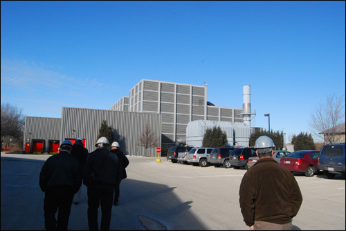
The ventilation experiments will be conducted at the UL Large Fire Research Facility in Northbrook, IL. From the exterior, this facility simply looks like a large industrial building (see Figure 2). However, the interior of the structure includes a unique facility for fire research.

Figure 2. UL Large Fire Research Facility

ul_large_fire_lab_outside

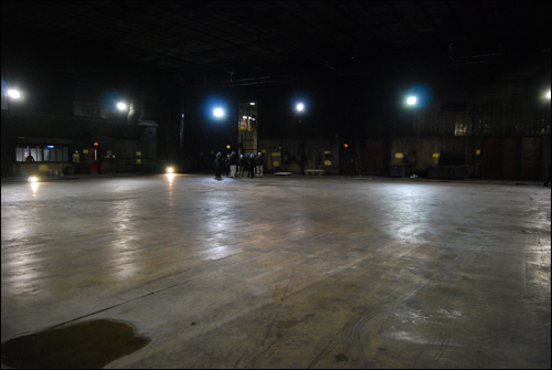
One of the facilities inside this building is a 100 x 120 (30.48 m x 36.58 m) with a ceiling height that is adjustable up to 50 (15.24 m) (see Figure 3). All of the smoke resulting from tests in this facility is exhausted through a system designed to oxidize unburned fuel and scrub hazardous products from the effluent prior to discharge to the atmosphere. Tests are monitored from a control room that overlooks the large burn room.

Figure 3. Large Burn Room

ul_large_fire_lab_inside

Over the next month, the two residential structures to be used for the ventilation experiments will be constructed inside the large burn room at the UL Large Fire Test Facility. After construction is complete, a series of 16 full scale fire experiments is planned to evaluate a range of different horizontal ventilation scenarios.

Research with the Fire Service

Steve Kerber has often stated that it is essential that scientists and engineers conduct research with, not for, the fire service. Engagement between researchers and firefighters on the street is essential in advancement of our profession. With this ventilation research project, Underwriters Laboratories is actively engaged in this process.

The outcome of this project will not simply be an academic paper (but there might be one or more of those as well). As part of the DHS grant, UL will be developing an on-line course to present the results of the experiments and their practical application on the fireground.

Happy Holidays,

Ed Hartin, MS, EFO, MIFireE, CFO

Positive or Negative:
Perspectives on Tactical Ventilation

Monday, May 25th, 2009

This post reviews articles on positive pressure ventilation written by Watch Manager Gary West of the Lancashire (UK) Fire and Rescue Service and Battalion Chief Kriss Garcia of the Salt Lake City Fire Department. Gary, Kriss, and I were recently in Australia for a meeting of the Institution of Fire Engineers (IFE) Compartment Firefighting Special Interest Group and to present at the 2009 International Firefighting Safety Conference hosted by IFE-Australia.

Gary and Kriss are both strong advocates of positive pressure ventilation (PPV) and its use to support fire attack (positive pressure attack (PPA)). In August 2008, Gary’s article Positive Thinking was published in Fire Risk Management Journal and October 2008, Kriss’s article The Power of Negative Thinking was published in FireRescue magazine. While the titles appear to be contradictory, both of my colleagues had a common theme; the importance of education and training to ensure safe and effective tactical ventilation on the fireground.

Common Elements

Gary and Kriss both emphasize the benefits of effective use of PPV while cautioning that education in practical fluid and fire dynamics and tactical ventilation concepts must be integrated with training in PPV/PPA tactics.

Positive Thinking

Gary provides an overview of the three phased approach to PPV training and implementation commonly used in the UK. This approach is designed around building understanding of key concepts and competence in tactical skills while minimizing risk.

Phase I-Post Fire Control PPV: In this phase, PPV is limited to clearing smoke after the fire has been controlled. In many respects this is the simplest and safest application of PPV.

Phase 2-Defensive PPV: In Phase 2, PPV is used during firefighting operations to clear smoke logged areas not involved in fire. This approach requires confinement of the fire using structural barriers (e.g., closing doors) and placement of hoselines. This tactical approach is less common in the United States, likely due to differences in construction. However, use of PPV to clear and then pressurize attached exposures can be an effective tactic in limiting smoke and fire spread.

Phase 3-Offensive PPV (PPA): In the third phase, PPV precedes fire attack and has a direct influence on fire behavior as well as clearing smoke from the entry path and uninvolved areas of the building.

Gary concludes with reinforcement of the importance of education and training prior to implementation and the criticality of ongoing training and development:

It must be understood that PPV is a tool that will save the lives of casualties, and also reduce the risk to firefighters, if used correctly. Initial training should cover all aspect of fan configurations, the different phases of PPV, and include an understanding of the way in which fire behaves generally [emphasis added], among other things.

However, it cannot be emphasized enough that, if used incorrectly, PPV is a potentially life-threatening and, as such, an ongoing training and development programme ought to be available to all users [emphasis added] (P. 49).

Critique of Positive Thinking

Gary provides a solid overview of the three phased approach to PPV training and implementation used in the UK and advocates for progression to Phase 3, positive pressure ventilation in support of fire attack. However, I take exception to two statements made in this article.

The first relates to the relationship between the size of inlet and exhaust opening. “It is widely understood that the size of the exhaust(s) must add up to less than the surface are of the inlet in order that positive pressure is achieved.” This is incorrect. As outlined in my previous post, Positive Pressure Ventilation: Inadequate Exhaust, the exhaust opening should be at least equal to the size of the inlet and preferably two to three times the area of the inlet opening.

The second statement relates to water application technique. “Students have a temptation to apply water using pulsing and gas-cooling techniques. However, it is not necessary in this mode of PPV [Phase 3]. While of less concern than inadequately sized exhaust openings, use of PPV does not necessarily negate the use of gas cooling. Depending on firefighters operating location and conditions encountered, cooling hot gases may still be necessary, particularly away from the path leading from inlet to outlet. Nozzle techniques and water application should be determined based on conditions, not the ventilation tactic being used. However, that said, Gary is correct that excess steam produced during attack in the fire compartment will be carried out the exhaust opening.

Negative Thinking

Kriss shares much of Gary’s perspective regarding the value of PPV and in particular its use to support fire attack (Phase 3/PPA). However, the main focus of The Power of Negative Thinking is on the practical aspects of the fluid dynamics involved in PPV. Kris points out that the application of positive pressure at an inlet simply adds a slight amount of pressure to direct the flow of fire effluent from the inlet to the exhaust opening(s).

Kriss states that “When PPA goes wrong, it’s usually attributable to one or two conditions, or their combination. First, mistakes result from a lack of coordination and control on the fireground including a lack of department wide training and education in the use of PPA.

Second, problems may arise from insufficient or not forward exhaust. When products of combustion are emitted under pressure adhead of the attack crews, substantial exhaust is need (P. 39).

One of the most important points that Kriss raises in this article is the importance of reading conditions at the inlet opening (which he refers to as the “ventilation” opening). “If heavy smoke and/or fire is returning to the attack entrance [and] exhausting above the blower, do not enter (p. 39) [additional emphasis added].

This article also outlines initial considerations for using PPV in support of fire attack Phase 3/PPA). Of particular importance is training and educating members in theory, application, and precautions involved in the offensive use of PPV. In addition, departments training and implementing the use of this tactic must define when it will be used (e.g., fire conditions, building types).

Critique of Negative Thinking

This article raises important points in developing an understanding of why PPV works (e.g., pressure differences) and provides a straightforward explanation of its safe use in support of fire attack. However, Kriss indicates that the pressure generated by the blower is less than that created by the fire and expansion of steam due to fire control operations. This is inconsistent with the results of research conducted by NIST (Kerber & Madryzkowski, 2008; 2009). On a related note, Kriss’s assumptions regarding pressure generated by steam expansion are dependent on excessive or inappropriate water application during fire suppression operations (which is not necessarily a given).

Final Thoughts

In these two articles, Gary and Kriss raise a number of important points and focus attention on the importance of understanding not simply what and how, but why. Kriss’s emphasis on the importance of having a decision-making framework and assessing conditions to determine if PPV is working prior to entry is absolutely critical. Sometime in the next couple of months I will expand on the topic of command, control, and coordination of fire control and ventilation.

Ed Hartin, MS, EFO, MIFireE, CFO

References

West, G. (2008, August). Positive thinking. Fire Risk Management, 46-49.

Garcia, K. (2008, October) The power of negative thinking. Fire Rescue, 38-40. Retrieved May 24, 2009 from http://positivepressureattack.com/images/pdfs/PowerOfNegativeThinking.pdf

Kerber, S. & Madrzykowski, D. (2008).Evaluating positive pressure ventilation In large structures: school pressure and fire experiments. Retrieved May 17, 2009 from http://www.fire.nist.gov/bfrlpubs/fire08/PDF/f08016.pdf.

Madrzykowski, D. & Kerber, S. (2009). Fire Fighting Tactics Under Wind Driven Conditions. Retrieved (in four parts) February 28, 2009 from http://www.nfpa.org/assets/files//PDF/Research/Wind_Driven_Report_Part1.pdf; http://www.nfpa.org/assets/files//PDF/Research/Wind_Driven_Report_Part2.pdf; http://www.nfpa.org/assets/files//PDF/Research/Wind_Driven_Report_Part3.pdf; http://www.nfpa.org/assets/files//PDF/Research/Wind_Driven_Report_Part4.pdf.

Positive Pressure Ventilation:
Inadequate Exhaust

Thursday, May 21st, 2009

As discussed in my last post, lack of an adequate exhaust opening is a common factor when use of positive pressure ventilation causes or increases the severity of extreme fire behavior. Unfortunately there has not been a great deal of research examining why this is the case. Part of the challenge in conducting a scientific investigation of this issue is the tremendous variability in building configuration and fire conditions. Control of these variables becomes more difficult as building configuration becomes more complex and multiple fire scenarios are considered. However, this does not preclude improvement of our understanding of this important issue.

Burning Regime

How an increase in ventilation influences fire behavior is largely (but not entirely) dependent on burning regime. If the fire is fuel controlled, fire development is dependent on the characteristics, configuration and amount of fuel. When a compartment fire becomes ventilation controlled, fire development is limited by the available oxygen. In the ventilation controlled burning regime, increased ventilation results in increased heat release rate. See my earlier post Fuel and Ventilation for additional information on burning regime.

In most ventilation controlled fires, the concentration of gas phase fuel (i.e., unburned pyrolyzate and flammable products of incomplete combustion) is not sufficient to present threat of backdraft. In these cases, increased ventilation will generally result in one of the following outcomes:

  • Increase in heat release rate that is not sufficient to result in a rapid transition to a fully developed fire (flashover)
  • Rapid increase in heat release rate that results in flashover and a fully developed fire.
  • Intervention by firefighters to control the fire before ventilation induced flashover can occur.

If the concentration of gas phase fuel is sufficient to present threat of backdraft, increased ventilation may result in a backdraft…or not (depending on the extent of mixing of air and smoke, presence of an adequate ignition source, etc.).

The greater the extent to which the fire is ventilation controlled and the higher the concentration of gas phase fuel, the greater the potential for extreme fire behavior following increases in ventilation. Positive pressure ventilation influences this process in several ways, if effective, gas phase fuel is removed from the structure (often burning outside the exhaust opening). If PPV is not effective, increased air flow is accompanied with turbulence and resultant mixing of fuel an air which increases the probability of ignition and rapid fire progression. In addition, pressure applied at the outlet increases confinement which may increase the violence of extreme fire behavior phenomena such as backdraft.

Fluid Dynamics

Movement of fluids (liquids and gases) should be of significant interest to firefighters. Both fireground hydraulics and tactical ventilation require an understanding of fluid dynamics. In examining the influence of inadequate exhaust opening size on the effectiveness of PPV and potential for extreme fire behavior, I found some parallels with fireground hydraulics.

Laminar Flow: Smooth movement of a fluid in parallel layers with little disruption between the layers. The following video clip illustrates laminar flow in a pipe.

Turbulent Flow: Fluid flow characterized by eddies and vortexes disrupting smooth movement. The following video clip illustrates turbulent flow in a pipe.

A number of characteristics influence flow characteristics when a fluid moves through a conduit such as a pipe, hoseline, or even a building. These include fluid characteristics such as viscosity and density, the roughness of the conduit, restrictions to flow, and velocity of the fluid.

For example, friction loss in 1-1/2″ (38 mm) hose is higher than that in 1-3/4″ (45 mm) hose at the same flow rate. Why? Velocity must be higher to move the same flow rate through the smaller hose. This results in increased turbulence and resulting loss in pressure. If a discharge gate is partially closed, this obstructs the waterway, creating turbulence and increasing friction loss. As illustrated in this example, increased velocity and the presence of obstructions both increase turbulence. How does this apply to PPV?

The extent of turbulence as air and fire effluent (smoke and fire gases) move through a building is influenced by the configuration of the building (e.g., walls, doorways), obstructions (e.g., furniture), and velocity. Turbulence increases mixing of fire effluent and air. If the concentration of unburned pyrolizate and flammable products of incomplete combustion is high, turbulence increases the potential of a flammable mixture. In addition, increased oxygen concentration and air movement across surfaces can result in transition from surface to flaming combustion, providing a source of ignition for the flammable mixture of fire effluent and air.

Outlet/Inlet Ratio

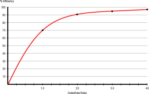
When using natural ventilation, the size of the inlet opening(s) should be larger than the exhaust opening(s). However, with positive pressure ventilation this is reversed. When using PPV. exhaust opening(s) should be at least as large and preferably two to three times as large as the inlet opening as illustrated in Figure 1.

Figure 1. PPV Efficiency Curve

ventilation_efficiency_curves

Note: Adapted from Fire Ventilation (Svensson, 2000, p. 71)

For a detailed examination of the physics and mathematical explanation of how the positive pressure ventilation efficiency curve is derived, see Stefan Svensson’s excellent text Fire Ventilation.

If the outlet size is adequate, a unidirectional ventilation flow from inlet to outlet is created. If opening size is inadequate, turbulence is increased as fire effluent and air seeks an exit path. If no opening is made or if the opening is extremely small, fire effluent may push back out the inlet opening.

Watch the following video clip and focus your attention on the exhaust opening on Side B (at approximately 0:19) and fire behavior indicators immediately after the blower is placed at the door on Side A and started (at approximately 3:00)


Find more videos like this on firevideo.net

Even though there was an exhaust opening, it was of inadequate size. While this fire was likely progressing towards a ventilation induced flashover due to the effects of natural horizontal ventilation, increased airflow and turbulence caused by ineffective PPV likely was a contributing factor in the way that this extreme fire behavior phenomena occurred.

Important: Implementation of PPV after entry and before the fire has been located and controlled presents a significant risk to firefighters. Risk can be minimized by either using positive pressure attack (implementing PPV prior to entry) or locating and controlling the fire before implementing PPV.

Next Steps

In the Education vs. Training in Fire Space Control, Kris Garcia (2008) wrote that we need to increase our focus on ventilation education, rather than simply training on ventilation skills. Effective use of PPV to support fire attack or following fire control requires an understanding of fire and fluid dynamics as well as skill in creating openings and the placement and operation of blowers.

My next post will examine review Positive Thinking, an article by Watch Manager Gary West of the Lancashire Fire Rescue Service (UK) published in the August 2008 issue of Fire Risk Management. In this article, Gary provides an excellent overview of the approach to PPV training and implementation taken by the UK fire service.

References

Svensson, S. (2005). Fire ventilation. Karlstad, Sweden: Swedish Rescue Services Agency.

Garcia, K. (2008, September). Education vs. training in fire space sontrol. Fire Engineering. Retrieved May 21, 2009 from http://positivepressureattack.com/images/pdfs/EdVsTng-GarciaFESept08.pdf

West, G. (2008, August). Positive thinking. Fire Risk Management, 46-49.

Positive Pressure Ventilation:
Did You Ever Wonder Why?

Monday, May 18th, 2009

Effective use of positive pressure ventilation aids in fire control and provides increased tenability throughout the fire building. However, inappropriate or ineffective use of this tactic has resulted in numerous near misses, injuries, and more than a few line of duty deaths. In many of these cases, positive pressure was applied with an inadequate exhaust opening.


Find more videos like this on firevideo.net

Did you ever wonder why the size and location of the exhaust opening is critical to safe and effective use of positive pressure ventilation? If not, maybe you should!

A Quick Review

As discussed in an earlier post (see Language and Understanding: Extreme Fire Behavior), common language and definitions are critical to developing a shared understanding. To that end, I want to start this examination of positive pressure ventilation (PPV) with a brief review of terminology used in this post.

Ventilation: The exchange of the atmosphere inside a compartment with the atmosphere outside the compartment. Ventilation is ongoing in all habitable spaces. Under fire conditions, this involves exit of smoke and intake of fresh air (if smoke is visible, ventilation is occurring).

Tactical Ventilation: Planned, systematic, and coordinated removal of heat, smoke, and fire gases (fire effluent) and their replacement with fresh air. There are three important parts of this definition, 1) tactical ventilation is part of the overall tactical plan and is coordinated with other fireground operations (particularly fire control), 2) hot fire effluent is removed, and 3) fresh (cooler) air is introduced into the compartment.

Note: I gave a bit of thought to use of the terms smoke and fire effluent in this discussion of ventilation. The International Standards Organization (ISO) definition of smoke focuses on the visible products of combustion while fire effluent includes all gaseous, aerosol, and particulates generated by combustion. The National Fire Protection Association (NFPA) definition of smoke is comparable to the ISO definition of fire effluent. Given that the traditional definition of (tactical) ventilation refers to “heat, smoke, and fire gases” (IFSTA, 2008, p. 541), I will use the term fire effluent as the broader, more encompassing term (inclusive of smoke and fire gases).

Natural Ventilation: Use of pressure and density differences generated by the higher temperature of gases inside the compartment than outside and ambient wind conditions to accomplish the exchange of hot fire effluent and air.

Assisted Ventilation: These tactics use mechanical or hydraulically generated pressure to influence and increase the exchange of fire effluent and air. Assisted ventilation includes the use of fog streams and fans to reduce pressure at the exhaust opening (negative pressure ventilation) and use of fans or blowers to increase pressure at the inlet opening (positive pressure ventilation).

Positive Pressure Ventilation (PPV): Use of a blower at the inlet opening to increase the pressure differential between the inlet and exhaust opening to control and increase the exchange of fire effluent and air.

Positive Pressure Attack (PPA): This term was coined by Garcia, Kauffmann, & Schelble (2006) to differentiate positive pressure ventilation initiated prior to fire attack from use of this tactic following fire control operations. From a physics perspective, PPV and PPA are the same, the term PPA simply designates the sequence in which the tactic is performed.

Exhaust Opening: The opening(s) used for removal of fire effluent. Note that this opening may be created by unplanned ventilation due to fire effects, civilians, or freelancing responders or it may be created as the result of tactical action. Remember that any location where flames and/or smoke is visible is an exhaust opening.

Inlet Opening: The opening(s) used to introduce fresh air into the compartment. As with exhaust openings, inlet openings may be unplanned or planned. Openings may serve simply as an inlet or may serve as both an inlet and outlet with fire effluent exiting at the top and air entering at the bottom (bi-directional air track).

Smoke Movement in Buildings

Fluids (like fire effluent) flow from areas of higher pressure to areas of lower pressure. In a compartment fire, energy released by combustion raises the temperature of the fire effluent and entrained air. As temperature increases, gases expand and become less dense (more buoyant). However, when gases are confined, increased temperature results in increased pressure. These differences in density and pressure result in movement of smoke out of the compartment and inward movement of air from outside the compartment. This exchange may be through normal building leakage, unplanned ventilation, or tactical ventilation.

The pressure generated by a fire inside a compartment is dependent on the heat release rate, ventilation (openings), and resulting temperature inside the compartment. However, NFPA 92A Standard for Smoke-Control Systems Utilizing Barriers and Pressure Differences (NFPA, 2006) specifies pressure differences in non-sprinklered buildings of between 12.5 Pascal (Pa) and 44.8 Pa to overcome the pressure resulting from hot gases at a temperature of 927o C (1700o F) next to the smoke barrier (these pressures include a 7.4 Pa safety factor). If the safety factor is removed, the pressure generated by a fire in a non-sprinklered occupancy would likely be between 5 Pa and 37.3 Pa. All very interesting, but what is a Pascal?

While firefighters in the United States are generally familiar with pounds per square inch (psi) as a unit of measure for pressure, the standard international unit for pressure is the Pascal (P). A Pascal is an extremely small unit (1 psi = 6895 Pa) roughly equivalent to the pressure exerted by a sheet of writing paper laying on a flat surface. As you can see, the pressure generated by the fire is quite small, but more than adequate to result in significant movement of fire effluent!

Two key points that influence movement of fire effluent and ventilation under fire conditions:

  • If the temperature of fire effluent is higher than that of the ambient air it will tend to rise.
  • Fire effluent flows from areas of higher pressure to areas of lower pressure.

PPV Basic Concepts

Many firefighters think that they understand positive pressure ventilation and how it should (and should not) be used on the fireground. Some do. However, there are a number of common misconceptions and a great deal of misunderstanding when it comes to effective application of this tactic.

A good starting point is to examine the fundamental purpose of the use of positive pressure in tactical ventilation and anti-ventilation. “The purpose of the positive pressure ventilation fan is to create pressures higher than that of the fire to manage where the smoke and hot gases flow” (Kerber & Madrzykowski, 2008). When used in tactical ventilation, positive pressure can be used to control air track and speed the removal of fire effluent from the compartment. In anti-ventilation (e.g., pressurization of a stairwell or attached exposure), positive pressure is used to confine the fire effluent.

The basic sequence of positive pressure tactical ventilation is as follows

  1. Size-up and dynamic risk assessment (ongoing)
  2. Determination that positive pressure is indicated (and not contraindicated)
  3. Identification of appropriate and adequate exhaust openings
  4. If necessary creating or enlarging exhaust openings
  5. Application of positive pressure at the inlet
  6. Verification that positive pressure ventilation is working

Positive pressure ventilation is an extremely powerful tool that can rapidly clear smoke logged areas of the building. However, if used without thinking and understanding the influence of ventilation on fire behavior, it can cause extreme fire behavior even more quickly. The following criteria should be met for safe and effective use of positive pressure ventilation:

  • Firefighters understand the use of PPV and are skilled in its use
  • The required tools are available
  • Location and extent of the fire is known Svensson, 2000). This is not an absolute requirement, but influences the most appropriate location for the exhaust opening)
  • A charged hoseline is in place for fire control (Svensson, 2000)
  • Backdraft conditions are not present (Svensson, 2000; Garcia, Kauffmann, & Schelble, 2006).
  • Victims or firefighters are not between the fire and the exhaust opening (Svensson, 2000)
  • Victims or firefighters are not in the exhaust opening (Garcia, Kauffmann, & Schelble, 2006)
  • Ventilation openings can be controlled and an adequate exhaust (preferably 2 to 3 times the size of the inlet) opening is provided (Svensson, 2000).
  • Positive control of the blower (the ability to start and stop positive pressure immediately)
  • Ventilation is coordinated with fire attack (Svensson, 2000; Garcia, Kauffmann, & Schelble, 2006). This requires communication with personnel at the outlet, inlet, interior working positions, and Command.

Common Problems

Kriss Garcia, co-author of Positive Pressure attack for ventilation & firefighting indicates that most situations where use of positive pressure ventilation resulted in occurrence of extreme fire behavior or some other adverse outcome generally involve one or more of the following (personal communication, May 2006):

  • Lack of an exhaust opening
  • Inadequate exhaust opening size
  • Lack of command, control, & coordination

More to Follow

My next post will get to into the nuts and bolts of exhaust opening size and why use of positive pressure with an inadequate exhaust opening can result in extreme fire behavior.

References

Garcia, K., Kauffmann, R. & Schelble, R. (2006). Positive pressure attack for ventilation & firefighting. Tulsa, OK: Penwell.

International Fire Service Training Association (IFSTA). (2008). Essentials of firefighting (5th ed.). Stillwater, OK: Fire Protection Publications.

Kerber, S. & Madrzykowski, D. (2008).Evaluating positive pressure ventilation In large structures: school pressure and fire experiments. Retrieved May 17, 2009 from http://www.fire.nist.gov/bfrlpubs/fire08/PDF/f08016.pdf.

National Fire Protection Association (NFPA). (2006). NFPA 92A. Standard for smoke-control systems utilizing barriers and pressure differences. Quincy, MA: Author.

Contra Costa County LODD: Part 2

Monday, May 11th, 2009

This post continues examination of the incident that took the lives of Captain Matthew Burton and Engineer Scott Desmond early on the morning of July 21, 2007. Captain Burton and Engineer Desmond died while conducting primary search in a small, one-story, wood frame dwelling with an attached garage at 149 Michele Drive in San Pablo (Contra Costa County), California.

This post focuses on firefighting operations, key fire behavior indicators, and firefighter rescue operations implemented after Captain Burton and Engineer Desmond were discovered after rapid fire progression in the area in which they were searching.

Firefighting Operations

Based on the report of trapped occupants, E70 immediately placed a 150′ preconnected 1-3/4″ (45 m 45 mm) line into service using apparatus tank water. The officer of E70, seeing what he believed to be E74 arriving he passed command to the E74 officer. Unfortunately, the second arriving engine was E73 (using apparatus normally assigned to Station 74 and marked E74).

Note: This incomplete passing of command resulted in loss of command, control, and coordination of tactical operations until the arrival of BC7 at 0202 and formally assumed command at 0205. All tactical operations prior to 0205 were the result of independent action by first alarm companies.

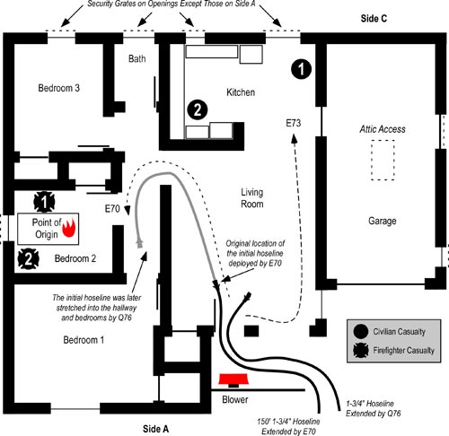
The crew of E70 (officer and firefighter) initiated fire attack through the door on Side A and advanced 3′-5′ (0.9-1.5 m) through the door and quickly knocked down flaming combustion in the living room and through dispatch, requested the first arriving truck to establish vertical ventilation. Retrieving a thermal imaging camera (TIC) from the apparatus, the crew of E70 began a left hand search (towards the bedrooms), but left the hoseline just inside the door on Side A (see Figure 1)

Figure 1. Floor Plan-149 Michelle Drive

figure_2_michele_dr_floor_plan

E73 hand stretched 200′ of 5″ (127 mm) supply line to a nearby hydrant. As he returned from the hydrant the firefighter from E73 observed a large volume of smoke from Side B. E73 officer tasked E70 engineer with placing a blower at the door on Side A. E73 (officer and firefighter) entered through the door on Side A and began a right hand search (taking the opposite direction from E70). E73 encountered poor visibility, but moderate temperature. While E73 conducted the search, E73 engineer shut off the natural gas service to the house.

E69 arrived at 0157 and prepared to perform vertical ventilation. The officer performed a size-up while the engineer obtained a chain saw and the firefighter placed a 14 ladder to provide access to the roof at the A/D corner. E70 engineer, asked the E69 officer about placing a blower to the front door (as previously ordered by the officer of E73) and he answered in the affirmative. The engineers from E70 and E73 placed a blower into operation 3′ (0.9 m) from the front door due to a half wall that partially enclosed the porch.

Note: No information is provided in the report regarding air track prior to or following pressurization of the building. The only substantive exhaust opening at the time the blower was placed into operation was the window in the living room immediately adjacent to the door on Side A.

E73 located the first civilian casualty, a female occupant in the kitchen (see Figures 2 and 5). As they removed the victim, both visibility and temperature increased dramatically. As they move the victim through the living room, they observed rollover coming from the hallway leading to the bedrooms (see Figures 2 and 5). The E73 officer briefly operated the hoseline left in the living room by E70 to control flaming combustion in the upper layer. The blower was turned 90o to permit removal of the victim, but was then returned to its original operating position. E69 officer assigned the E69 firefighter to assist E73 with patient care on Side A.

The E69 officer and engineer proceeded to the roof and began making a vertical ventilation opening on Side A roof, over the hallway. At 0159 Q76 arrived and while the officer was donning his breathing apparatus (BA), the window in Bedroom 1 failed suddenly followed by a significant increase in flaming combustion from the windows in Bedroom 1 and 2 on Sides A and B.

The firefighter from E73 who was providing emergency medical care to the civilian fire victim observed that the window in Bedroom 1 which had been cracked with some discharge of smoke, failed violently with glass blowing out onto the lawn and a large volume of flames venting from the window for a period of 10 to 15 seconds (see Figure 2).

Figure 2. Extreme Fire Behavior

figure_6_extreme_fb

Note: Adapted from eight seconds of video was shot by Q76 firefighter from in front of Exposure D, looking towards the A/D corner of the fire building.

Figure 3. Post Fire Photo from in Front of Exposure D

figure_7_google_maps1

Note: This screenshot from Google Maps Street View is from a similar angle as the video taken by Q76 firefighter and is provided to provide a point of reference and perspective for the video.

The E73 officer reentered the building and initiated fire attack using the hoseline left in the living room. E70 engineer stretched a second 150′ 1-3/4″ (45 m 45 mm) line to the front door. The second line was stretched into the building by Q76. Immediately after entering through the door on Side A, the Q76 met E73 officer who was exiting with low air alarm activation. Q76 took over the initial hoseline and worked their way down the hallway leading to the bedrooms, leaving the second line in the living room (see Figure 2) Q76 encountered poor visibility and high temperature with flames extending out of Bedrooms 1 and 2 and rollover in the hallway.

Shortly after exiting the building E73 officer advised E73 engineer that he was “out of air” [he was likely in a low air condition with low air alarm sounding rather than completely out of air] and expressed concern regarding E70’s air status.

Battalion 7 (BC7) arrived at 0202 and attempted to make face-to-face contact with Command (E70) as he had not heard E70 attempt to pass command to E74. At 0203, BC7 confirmed that a medic unit was responding and requested that the medic upgrade from Code 2 to Code 3. (Code 2 is a non-life threatening medical emergency requiring immediate response without the use of red lights or siren. Code 3 is a a medical emergency requiring immediate response with red lights and siren.) BC7 then attempted to contact E70 on the tactical channel and asked other crews operating at the incident about the status of E70. At 0205, BC7 ordered a second alarm and attempted to contact E70 on non-assigned tactical channels (in the event that their radios were inadvertently on the wrong channel). The second alarm added three engines (E74, E75, and E73) and a battalion chief (BC71) to the incident.

While BC7 was attempting to locate E70, Q76 was operating in the hallway and bedrooms in an effort to control the fire. They knocked the fire down in Bedroom 2 and controlled the rollover extending from Bedroom 1 down the hall. Q76 officer scanned Bedroom 2 with a TIC, but did not observe any victims. Q76 then advanced to Bedroom 1.

E69 completed a 6′ x 6′ (1.8 m x 1.8 m) ventilation opening in the roof on Side A, two thirds of the way from their access point at the A/D corner to Side B. Immediately after making the opening, they observed minimal smoke discharge (and were able to see items stored in the attic and the attic floor (original roof). They attempted to breach the attic floor, but were unable to do so (as it was constructed of 2″ x 6″ (51 mm x 152 mm) tongue and groove planks).

At 0206, after repeated unsuccessful attempts to contact E70, BC7 transmitted a report of a missing firefighter and assumed Command. Command requested an additional engine (E68) be added to the second alarm assignment. Battalion 64 (BC64) added himself to the incident and advised dispatch.

As E69 exited the roof they heard a loud pop and observed flames exiting the roof ventilation opening a distance of 8′-10′ (2.4-3.0 m). After knocking down the fire in Bedroom 1 Q76 moved back to Bedroom 2. Failure of the gypsum board on the wall between Bedrooms 1 and 2 allowed operation of the stream from their hoseline into both bedrooms.

While at the doorway of Bedroom 2, Q76 observed a substantial volume of fire in the attic through a small hole in the hallway ceiling (see Figure 4) and attempted to apply water into the attic. However, their stream was ineffective.

Figure 4. Hallway Ceiling.

figure_9_hole_in_ceiling

Note: Adapted from Contra Costa Fire Protection District Photos, Investigation Report: Michele Drive Line of Duty Deaths. Brightness and contrast adjusted to increase clarity.

After exiting the roof, E69 proceeded counter clockwise around the building to Side C where they removed window screens and broke out several panes of glass, but did not observe an appreciable discharge of smoke. Continuing around the B/C corner, E69 observed flames from the window of Bedroom 2 and the attic.

At 0208 Command (BC7) repeatedly attempted to contact E70 by radio on the tactical channel. Unsuccessful, he requested an additional Code 3 ambulance and advised that the status of the missing firefighters was unknown.

E69 met with Command (BC7) and was assigned to continue primary search for the second reported occupant. E69 firefighter and engineer began the search while the officer replaced his SCBA cylinder. As they entered, they picked up a hoseline (second 1-3/4″ (45 mm) hoseline) and used it to extinguish small areas of fire as they moved towards the kitchen. Q76 handed off their TIC to E69 as they exited the building with low air alarms sounding.

Q76 replaced SCBA cylinders and was tasked with search for E70 on the exterior. While conducting this search, they observed flames 10′-15′ (3.0-4.6 m) in length issuing from the gable vent on Side B.

After E69 officer rejoined his crew in the kitchen, they located the second civilian casualty who was determined to be diseased (see Figure 2). Command (BC7) ordered E69 to defer removing the victim and continue searching for E70.

Firefighter Rescue Operations

E69 walked through the interior of the dwelling looking for E70 and used a hoseline to knock down fire still burning in the closet of Bedroom 2. E69 advised command that E70 was not inside, but was instructed to conduct a second search of the interior.

At 0127, Command (BC7) asked dispatch to conduct a “head count” [personnel accountability report (PAR)]. Second alarm resources arrived between 0218 and 0221.

E69 reentered the building and conducted a thorough search for E70. At 0221, Command (BC7) ordered companies to “evacuate” [withdraw from] the building. Based on the urgency of his assignment to locate E70, E69 officer decided to continue the search into Bedroom 2. At approximately 0222, E69 located Captain Burton (fire service casualty 1) under debris on the right side of the bed (see Figure 2). His facepiece was still in place and his low air alarm was ringing slowly. E69 attempted to remove the Captain, but were only able to move him to the doorway to Bedroom 2 before smoke conditions worsened and visibility decreased. Near exhaustion, one member of the crew experience low air alarm activation and became disoriented requiring assistance to exit to the door on Side A.

Command (BC7) assigned Q76 to assist with the search. As E69 exited, they advised Q76 that they had located one member of E70 in the bedroom. After exiting, E69 advised Command (BC7) that they had located one member of E70 and that he appeared to be diseased and that they were having difficulty in removing him. Q76 quickly located Captain Burton inside the doorway of Bedroom 2 and removed him to Side A at 0228. E73 attempted resuscitation, but quickly determined that the Captain’s injuries were fatal.

BC64 and E76 officer continued the search in Bedroom 2 and located Engineer Desmond (fire service casualty 2) on the left side of the bed (see Figure 2). E72 assisted in controlling the fire in Bedroom 2 and the removal of the second member of E70 on a backboard. Engineer Desmond was removed from the building at approximately 0224. After both members of E70 were removed, crews removed the deceased civilian occupant.

Timeline

Review the Michelle Drive Timeline (PDF format) to gain perspective of sequence and the relationship between tactical operations and fire behavior.

Questions

The following questions focus on fire behavior, influence of tactical operations, and related factors involved in this incident.

  1. The E73 officer tasked E70 engineer with placement of a blower at the door on Side A (use of this tactic was reaffirmed by the E69 officer). What air track did this use of positive pressure create and what effect did this have on 1) conditions in the living room and kitchen and 2) in the hallway and bedrooms? Why do you think that this was the case?
  2. What type of extreme fire behavior phenomena occurred in this incident? Do you agree with the Contra Costa County Fire Protection District report conclusion that this was a fire gas ignition or do you suspect that some other phenomenon was involved?
  3. How did the conditions necessary for this extreme fire behavior event develop (address both the fuel and ventilation sides of the equation)?
  4. What was the initiating event(s) that lead to the occurrence of the extreme fire behavior that trapped Captain Burton and Engineer Desmond? How did the use of positive pressure ventilation influence the occurrence of the extreme fire behavior (if in fact it did)?
  5. What action could have been taken to reduce the potential for extreme fire behavior and maintain tenable conditions during primary search operations?
  6. How did building design and construction impact on fire behavior and tactical operations during this incident?

Deliberate Practice

Ed Hartin, MS, EFO, MIFireE, CFO

References

Contra Costa County Fire Protection District. (2008). Investigation Report: Michele Drive Line of Duty Deaths. Retrieved February 13, 2009 from http://www.cccfpd.org/press/documents/MICHELE%20LODD%20REPORT%207.17.08.pdf

National Institute for Occupational Safety and Health (2009). Death in the Line of Duty Report 2007-28. Retrieved May 5, 2009 from http://www.cdc.gov/niosh/fire/pdfs/face200728.pdf.

NIST Wind Driven Fire Experiments:
Wind Control Devices & Fire Suppression

Thursday, March 12th, 2009

Continuing examination of NIST’s research on Firefighting Tactics Under Wind Driven Conditions, this post looks at the results of experiments involving use of wind control devices and external water application.

In my last post, I posed several questions about wind control devices to “prime the pump” regarding wind driven fires and potential applications for use of wind control devices.

Questions

Give some thought to how wind can influence compartment fire behavior and how a wind control device might mitigate that influence.

  • How would a strong wind applied to an opening (such as the bedroom window in the NIST tests) influence fire behavior in the compartment of origin and other compartments in the structure?
  • How would deployment of a wind control device influence fire behavior?
  • While the wind control device illustrated in Figure 5 was developed for use in high-rise buildings, what applications can you envision in a low-rise structure?
  • What other anti-ventilation tactics could be used to deal with wind driven fires in the low-rise environment?

Answers: Thornton’s Rule indicates that the amount of oxygen required per unit of energy released from many common hydrocarbons and hydrocarbon derivatives is fairly constant. Each kilogram of oxygen used in the combustion of common organic materials results in release of 13.1 MJ of energy. Fully developed compartment fires are generally ventilation controlled (potential heat release rate (HRR) based on fuel load exceeds the actual HRR given the atmospheric oxygen available through existing ventilation openings). Application of wind can dramatically increase heat release rate by increasing the mass of oxygen available for combustion. In addition to increasing HRR, wind can significantly increase the velocity of hot fire gases and flames (and resulting convective and radiant heat transfer) between the inlet and outlet openings.

Deployment of a wind control device to cover an inlet opening (window or door), limits oxygen available for combustion to the air already in the structure and normal building leakage. In addition, blocking the wind will also reduce gas and flame velocity between the inlet and outlet.

While wind driven fires are problematic in high-rise buildings, the same problem can be encountered in low-rise structures and wind control devices may prove useful in some circumstances. However, exterior attack (discussed later in this post) is more feasible than in a high-rise building and other tactics such as door control may also prove essential in managing hazards presented by wind.

Test Conditions

As outlined in my earlier post, Wind Driven Fires, NIST conducted a number of different wind driven tests using the same multi-compartment structure. Experiment 3 involved evaluation of anti-ventilation tactics using a large wind control device placed over the bedroom window. Wind conditions of 6.7 m/s to 8.9 m/s (15 mph-20 mph) were maintained throughout the test.

As with the baseline test, two ventilation openings were provided. A ceiling vent in the Northwest Corridor and a window (fitted with glass) in the bedroom (compartment of origin). During the test the window failed due to fire effects and was subsequently fully cleared by the researchers to provide a full window opening for ventilation.

Figure 1. Isometric Illustration of the Test Structure

test_floor_plan_wind

Note: The location of fuel packages in the bedroom and living room is shown on the Floor Plan provided in Wind Driven Fires post.

Experiment 3 Wind Driven Fire

This experiment was one of several that investigated wind driven fire behavior and the effectiveness of a wind control device deployed over the bedroom window to limit inward airflow. The fire was ignited in the bedroom and allowed to develop from incipient to fully developed stage in the bedroom.

The fire progressed in a similar manner as observed in the baseline test described in my earlier post NIST Wind Driven Fire Experiments: Establishing a Baseline. In this experiment the fire involving the initial fuel packages (bed and waste container) and visible smoke layer developed slightly more slowly. However, the bedroom window failed more completely and 11 seconds earlier than in the baseline test.

Almost immediately after the window failed, turbulent flaming combustion filled the bedroom and hot gases completely filled the door between the living room and corridor and were impinging on the opposite wall. At 222 seconds (15 seconds after the window was completely cleared) flames were visible in the corridor and the hollow core wood door in the target room was failing with flames breaching the top corners of the door and a smoke layer developing in the target room. While most of the hot gases and flames were driven through the interior (towards the ceiling vent in the corridor), flames continued to flow out the top of the window opening (against the wind).

At 266 seconds conditions had further deteriorated in all compartments with no visibility in the corridor and increased deterioration of the door to the target room. At this point the air track at the window was completely inward (no flames outside the window).

The wind control device was deployed at 270 seconds. Unfortunately soot on the video cameras lenses precluded a good view of interior conditions. However, video from the thermal imaging camera no longer showed any flow of hot gases into the corridor (only high temperature).

At 330 seconds, shortly after removal of the wind control device flames were visible in the bedroom and the fire quickly progressed to a fully developed state. At 360 seconds, flames were pulsing out the window opening (against the wind).

The experiment was ended at 380 seconds and the fire was extinguished.

Heat Release Rate

As with the baseline test NIST researchers recorded heat release rate data during Experiment 3. As discussed earlier in this post, application of wind increased the amount of oxygen available for combustion and resulting heat release rate in comparison to the baseline test.

Figure 2. Heat Release Rates in Experiments 1 (Baseline) and 3 (Wind Driven)

hrr_experiment3

Note: Adapted from Firefighting Tactics Under Wind Driven Conditions.

Questions: Examine the heat release rate curves in Figure 2 and answer the following questions:

  • What effect did deployment of the wind control device have on HRR and why did this change occur so quickly?
  • How did HRR change when the wind control device was removed and why was this change different from when the window was vented?
  • What factors might influence the extent to which HRR changes when ventilation is increased to a compartment fire in a ventilation controlled burning regime?

Wind Control Device Research and Application

NIST has continued research into the practical application of wind control devices with tests in Chicago and New York involving large apartment buildings and realistic fuel loading. For additional information on these tests and video of wind control device deployment, visit the NIST Wind Driven Fires webpage.

Fire Control Experiments

NIST researchers also conducted a series of experiments in the same structure examining the impact of various fire control tactics. These included application of water using solid stream and combination nozzles (using a 30o fog pattern with continuous application). In addition, they examined the influence of coordinated deployment of a wind control device and low flow water application of water fog). In each of these tests, water was applied from the exterior of the structure through the bedroom window.

Water Fog Application: Experiment 6 involved application of water using a hoseline equipped with a combination nozzle at 90 psi (621 kPa) nozzle pressure, providing a flow rate of 80 gpm (303 lpm). The fog stream was initially applied across the window (no discharge into the bedroom). This had a limited effect on conditions on the interior. When applied into the room, the 30o fog pattern was positioned to almost completely fill the window. This action resulted in a brief increase (approximately 4 MW) and then a dramatic reduction in HRR.

Solid Stream Application: Experiments 7 and 8 involved application of water using a hoseline equipped with a 15/16″ smooth bore nozzle at 50 psi (345 kPa) nozzle pressure, providing a flow rate of 160 gpm (606 lpm). The solid stream was initially directed at the ceiling and then in a sweeping motion across the ceiling. In Experiment 8, the stream was then directed at burning contents in the compartment. Application of the solid stream had a pronounced effect, dramatically reducing heat release rate in both experiments.

Conditions varied considerably between these three tests (Experiments 6-8). This makes direct comparison of the results somewhat difficult. However, several conclusions can be drawn from the data:

  • Exterior application of water can be effective in reducing HRR in wind driven fires.
  • Both solid stream and fog application can be effective in reducing HRR under these conditions.
  • Continuous application of water fog positioned to nearly fill the inlet opening develops substantial air flow which can increase HRR (this works similar to the process of hydraulic ventilation, but in reverse).
  • A high flow solid stream may be more effective (but not necessarily more efficient) than a lower flow fog pattern if a direct attack on burning contents can be made.

Coordinated WCD Deployment and Water Application: Experiments 4 and 5 involved evaluations of anti-ventilation and water application using a small wind control device and 30 gpm (113.6 lpm) spray nozzle from under the wind control device. The effectiveness of the wind control device was similar to other anti-ventilation tests and application of low flow water fog resulted in continued decrease in HRR throughout the experiment.

Ed Hartin, MS, EFO, MIFireE, CFO

References

Madrzykowski, D. & Kerber, S. (2009). Fire Fighting Tactics Under Wind Driven Conditions. Retrieved (in four parts) February 28, 2009 from http://www.nfpa.org/assets/files//PDF/Research/Wind_Driven_Report_Part1.pdf; http://www.nfpa.org/assets/files//PDF/Research/Wind_Driven_Report_Part2.pdf;http://www.nfpa.org/assets/files//PDF/Research/Wind_Driven_Report_Part3.pdf;http://www.nfpa.org/assets/files//PDF/Research/Wind_Driven_Report_Part4.pdf.

NIST Wind Driven Fire Experiments:
Anti-Ventilation-Wind Control Devices

Monday, March 9th, 2009

My last post asked a number of questions focused on results of baseline compartment fire tests conducted by the National Institute for Standards and Technology (NIST) as part of a research project on Firefighting Tactics Under Wind Driven Conditions. This post looks at the answers to these questions and continues with an examination of NIST’s experiments in the application of wind control devices for anti-ventilation.

Questions

Generally being practically focused people, firefighters do not generally dig into research reports. However, the information on the baseline test conducted by NIST raised several interesting questions that have direct impact on safe and effective firefighting operations. First consider possible answers to the questions and then why this information is so important (the “So what?”!).

Figure 1. Heat Release Rate Comparison

hrr_comparison

Note: Adapted from Firefighting Tactics Under Wind Driven Conditions.

Heat Release Rate (HRR) Questions: Examine the heat release rate curves in Figure 1 and answer the following questions:

  • Why are these two HRR curves different shapes?
  • In each of these two cases, what might have influenced the rate of change (increase or decrease in HRR) and peak HRR?
  • What observations can you make about conditions inside the test structure and heat release rate (in particular, compare the HRR and conditions at approximately 250 and 350 seconds)?

Answers: The HRR test for the bed and waste container was conducted under fuel controlled conditions (oxygen supply was not restricted). The higher HRR in the compartment fire experiment results from increased fuel load (e.g., additional furniture, carpet). After reaching its peak, HRR in the compartment fire drops off slowly as the fire becomes ventilation controlled and the fire continues in a relatively steady state of combustion (limited by the air supplied through the lower portion of the bedroom window)

The rate of change in heat release rate under fuel controlled conditions is dependent on the characteristics and configuration of the fuel. However, in the case of the compartment fire test, the rate of change is also impacted by limited ventilation. As illustrated in the compartment fire curve, the fire quickly became ventilation controlled and HRR rose slowly until the window failed and was fully cleared by researchers.

At 250 seconds (when the window was vented) HRR rose extremely rapidly as the fire in the bedroom rapidly transitioned from the growth through flashover to fully developed stage. At 350 seconds the fire had again become ventilation controlled and was burning in a relatively steady state limited by the available oxygen.

The fully developed fire in the bedroom also became ventilation controlled due to limited ventilation openings, resulting in HRR leveling off with relatively steady state combustion based on the available oxygen.

Figure 2. Bedroom Temperature

bedroom_temp

Note: Adapted from Firefighting Tactics Under Wind Driven Conditions.

Temperature Questions: Examine the temperature curves in Figure 2 and answer the following questions:

  • What can you determine from the temperature curves from ignition until approximately 250 seconds?
  • How does temperature change at approximately 250 seconds? Why did this change occur and how does this relate to the data presented in the HRR curve for Experiment 1 (Figure 1)?
  • What happens to the temperature at the upper, mid, and lower levels after around 275 seconds? Why does this happen?

Answers: Temperature at the upper levels of the compartment increased much more quickly than at the lower level and conditions in the compartment remained thermally stratified until the ceiling temperature exceeded 600o C. At approximately 250 seconds, the compartment flashed over resulting in a rapid increase in temperature at mid and lower levels. This change correlates with the rapid increase in HRR occurring at approximately 250 seconds in Figure 1. Turbulent, ventilation controlled combustion resulted in a loss of thermal layering with temperatures in excess of 600o C from ceiling to floor. At around 275 seconds.

Figure 3. Total Hydrocarbons at the Upper Level

upper_level_thc

Note: Adapted from Firefighting Tactics Under Wind Driven Conditions.

Total Hydrocarbons (THC) Questions: Examine the THC curves in Figure 3 and answer the following questions:

  • Why did the THC concentration in the living room rise to a higher level than in the bedroom?
  • Why didn’t the gas phase fuel in the living room burn?
  • How did the concentration of THC in the bedroom reach approximately 4%? Why wasn’t this gas phase fuel consumed by the fire?

Answers: Oxygen entering the compartments through the window was being used by combustion occurring in the bedroom. Low oxygen concentration limited combustion in the living room and allowed accumulation of a higher concentration of unburned fuel. While the oxygen concentration in the bedroom was higher, the fire was still ventilation controlled and not all of the gas phase fuel was able to burn inside this compartment.

So What?

What do the answers to the preceding questions mean to a company crawling down a dark, smoky hallway with a hoseline or making a ventilation opening at a window or on the roof?

Emergency incidents do not generally occur in buildings equipped with thermocouples, heat flux gages, gas monitoring equipment, and pre-placed video and thermal imaging cameras. Understanding the likely sequence of fire development and influencing factors is critical to not being surprised by fire behavior phenomena. These tests clearly illustrated how burning regime (fuel or ventilation controlled) impacts fire development and how changes in ventilation can influence fire behavior. The total hydrocarbon concentration and ventilation controlled combustion in the living room would present a significant threat in an emergency incident. How might conditions change if the fire in the bedroom was controlled and oxygen concentration began to increase? Ignition of the gas phase fuel in this compartment could present a significant threat (see Fire Gas Ignitions) or even prove deadly (future posts will examine the deaths of a captain and engineer in a fire gas ignition in California).

Anti-Ventilation

For years firefighters throughout the United States have been taught that ventilation is “the planned and systematic removal of heat, smoke, and fire gases, and their replacement with fresh air”. This is not entirely true! Ventilation is simply the exchange of the atmosphere inside a compartment or building with that which is outside. This process goes on all the time. What we have thought of as ventilation, is actually tactical ventilation. This term was coined a number of years ago by my friend and colleague Paul Grimwood (London Fire Brigade, retired). It is essential to recognize that there are two sides to the ventilation equation, one is removal of the hot smoke and fire gases and the other is introduction of air. Increased ventilation can improve tenability of the interior environment, but under ventilation controlled conditions will result in increased heat release rate.

Another tactic change the ventilation profile and influence fire behavior and conditions inside the building is to confine the smoke and fire gases and limit introduction of air (oxygen) to the fire. Firefighters in the United States often think of this as confinement, but I prefer the English translation of the Swedish tactic, anti-ventilation. This is the planned and systematic confinement of heat, smoke, and fire gases and exclusion of fresh air. The concept of anti-ventilation is easily demonstrated by limiting the air inlet during a doll’s house demonstration (see Figure 4). Closing the inlet dramatically reduces heat release rate and if sustained, can result in extinguishment.

Figure 4. Anti-Ventilation in a Doll’s House Demonstration

doll_house_door

For a more detailed discussion of the relationship between ventilation and heat release rate see my earlier post on Fuel and Ventilation.

Air Track and Influence of Wind

Air track (movement of smoke and air under fire conditions) is influenced by differences in density between hot smoke and cooler air and the location of ventilation openings. However, wind is an often unrecognized influence on compartment fire behavior. Wind direction and speed can influence movement of smoke, but more importantly it can have a dramatic influence on introduction of air to the fire.

While the comparison is not perfect, the effects of wind on a compartment fire can be similar to placing a supercharger on an internal combustion engine (see Figure 5). Both dramatically increase power (energy released per unit of time).

Figure 5. Influence of Wind

supercharger

NIST Wind Control Device Tests

As discussed in Wind Driven Fires, the effects of wind on compartment fire behavior can present a significant threat to firefighters and has resulted in a substantive number of line-of-duty deaths. In their investigation of potential tactical options for dealing with wind driven fires, NIST researchers examined the use of wind control devices (WCD) to limit introduction of air through building openings (specifically windows in the fire compartment in a high-rise building) as illustrated in Figure 6.

Figure 6. Small Wind Control Device

wcd_small

Note: Photo from Firefighting Tactics Under Wind Driven Conditions.

Questions

Give some thought to how wind can influence compartment fire behavior and how a wind control device might mitigate that influence.

  • How would a strong wind applied to an opening (such as the bedroom window in the NIST tests) influence fire behavior in the compartment of origin and other compartments in the structure?
  • How would a wind control device deployed as illustrated in Figure 5 influence fire behavior?
  • While the wind control device illustrated in Figure 5 was developed for use in high-rise buildings, what applications can you envision in a low-rise structure?
  • What other anti-ventilation tactics could be used to deal with wind driven fires in the low-rise environment?

The Story Continues…

My next post will address the answers to these questions (please feel free to post your thoughts) and examine the results of NIST’s tests on the use of wind control devices for anti-ventilation.

References

Madrzykowski, D. & Kerber, S. (2009). Fire Fighting Tactics Under Wind Driven Conditions. Retrieved (in four parts) February 28, 2009 from http://www.nfpa.org/assets/files//PDF/Research/Wind_Driven_Report_Part1.pdf; http://www.nfpa.org/assets/files//PDF/Research/Wind_Driven_Report_Part2.pdf;http://www.nfpa.org/assets/files//PDF/Research/Wind_Driven_Report_Part3.pdf;http://www.nfpa.org/assets/files//PDF/Research/Wind_Driven_Report_Part4.pdf.

Ed Hartin, MS, EFO, MIFireE, CFO