Posts Tagged ‘ventilation’

Mass and Energy Balance in Fire Ventilation

Sunday, March 16th, 2014

Milestone! As I was preparing to upload this post, I realized that this is the 200th CFBT-US Blog Post since its inception in August of 2008. Quite a lot has happened since then. In 2008 there were few people in the fire service focused on the importance of fire dynamics to firefighting operations. Today it is a significant research focus and an ongoing topic of discussion throughout the US fire service. Progress is being made, but much remains to be done.

This post focuses on questions posed by firefighters in Europe and North America. Art Arnalich, a Fire Officer from Spain recently sent me a message asking for clarification and further explanation of the application of conservation of mass as it relates to fire ventilation. As always, questions form an excellent basis to examine what we think we know and how it applies in a practical context.

In my previous post, Large Vertical Vents are Good, But…, I stated:

Conservation of Mass: The mass of air entering a compartment (single compartment or building) must equal the mass of smoke and air exiting the building. This means that other than in the extremely short term, if smoke is exiting the building, air must be entering. This may be through one or more openings functioning solely as inlets or openings may be functioning as both inlets and outlets (with either a bi-directional flow or alternating (pulsating) flow). However, the mass of the inflow must equal that of the outflow.

Art writes: The first condition for the Principle of Conservation of Mass to be applied is that the physical system must be closed to all transfers of matter and energy. While a closed compartment could be considered as a nearly “closed system”, a venting structure suffers important transfers of matter and energy. If we were to consider a bigger system (let’s say the 100x100x100m cube in which the house and all of its fire gases are included) the PCM [principle of conservation of mass] applies… Being the structure volume constant, any exiting gases will create an interior drop of pressure that will instantly drag an equal volume of gases to enter. Inlets with the bigger pressure differentials (lower side) will observe the larger flows. Outflow volume must equal inflow volume unless significant pressure changes can take place (not likely). Since there is an important difference between inflow/outflow temperatures (and densities), inflow mass (mass=density x volume) does not equal outflow mass.

The amount of gases coming out of combustion as a result of the new oxygen flow has been disregarded. In an actual fire, outflow volume should be larger than inflow volume because combustion of products generates new gases in within the interior.

But that doesn’t mean that mass in = mass out if we just consider the house. Total mass of unburned air + mass of fuel + mass of all combustion products = constant. But to measure this we can’t consider the volume of the structure itself but the volume that contains all fire gases, unburned gases and the house.

Art Asks: Could you please explain the implications of Principle of Conservation of Mass applies at a molecular level…If Mass-in=Mass-out then there is no mass variation over time (dm/dt=0). This would mean that the total mass of the house before the fire equals its mass after the fire. That doesn’t make sense.

Conservation of Mass and Energy

Mass is neither created nor destroyed in chemical reactions. The mass of any one element at the beginning of a reaction will equal the mass of that element at the end of the reaction. If we account for all reactants and products in a chemical reaction, the total mass will be the same at any point in time in any closed system.

In combustion, if you consider the mass of the fuel and atmospheric oxygen before combustion, this must be the same as the mass of unburned fuel, unused oxygen, plus the products of combustion (this leaves out nitrogen and other thermal ballast that are not part of the combustion reaction). This is a bit different than the balance of the mass of smoke exiting the compartment and the mass of air entering.

I posed a similar question to Dr. Stefan Svensson from Lund University concerning the difference in the volume of products of combustion discharged and air intake from a single opening with a bi-directional air track. I discussed Art’s question with Stefan to ensure that my answer was clear and as accurate as possible (while maintaining a practical context).

In actuality, I should have stated that mass and energy must be balanced. Application of the principle of conservation of mass and energy in practical fire dynamics is an estimate and it applies on the molecular level (i.e. molecular mass). Usually we look at the building as a system in which the principle of conservation of mass and energy works as a rough estimate. If you define the system as a large cube that contains the building, the cube becomes the system.

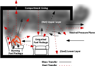
In considering mass balance in a compartment fire it is important to keep in mind that solid fuel in the compartment is undergoing pyrolysis; thermally decomposing into gas phase fuel. Some of the fuel burns producing a range of combustion products and some remains unburned. Smoke is comprised of air, products of combustion, and unburned pyrolizate.

As air, products of combustion, and pyrolizate are heated, the volume increases (but mass stays the same), cooler outside air flowing into the building is more dense (smaller volume, but the same mass). This results in approximate balance between of the mass of hot air and products of combustion exiting the building and the mass of cooler external air entering the building.

mass_energy_transfer
As smoke is a complex aerosol and its content varies considerably based the fuel that is burning and combustion efficiency, its density cannot be specified as a single value (at a given temperature). However, since air is a large constituent of smoke, I will use density of air for this example:

Density of Dry Air at 20o C: 1.205 kg/m3 (at Sea Level)

Density of Dry Air at 300o C: 0.616 kg/m3 (at Sea Level)

The implications of this difference in density is that if 1 m3 of hot air and products of combustion exit the building at 300o C, they will be replaced by approximately 0.5 m3 of cooler air (which will have the same mass as the exiting smoke and hot air. This differential will increase further if the temperature of the smoke is higher (resulting in lower density). It is important to note that the volume of air is not the same as the products of combustion and air that exit the compartment, but the mass is the same.

Pressure Differential and Flow

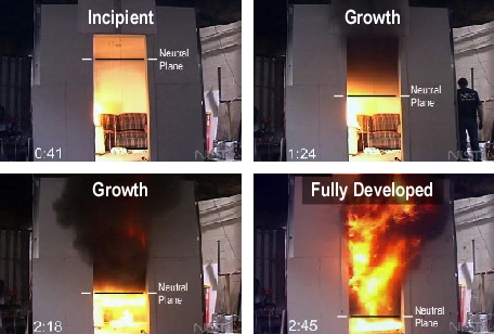
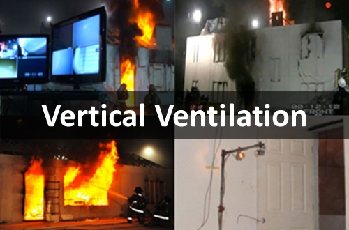
Smoke movement is due to both pressure and differences in density (gravity current). However, in general, the pressure differential between the interior of the building and the exterior is what causes smoke discharge. However, this pressure differential is not uniform and will be higher in the hot upper layer than in cooler air below (if a two layer environment exists inside the building). This is fairly simple to visualize when considering a single compartment. As shown in the following four photographs, hot smoke exits at the top of the door (above the neutral plane) and air enters at the bottom of the door (below the neutral plane). Movement of smoke in this case is the result of both the pressure resulting from increased temperature of the gases in the upper layer and the difference in density between the hot smoke (less dense) and the cooler air (more dense).

neutral_plane_burning_regime
Pressure is also influenced by building geometry, compartmentation, and external effects such as wind. Velocity, length of the flow path, and the size of the exhaust opening(s) will all influence flow in much the same manner as velocity, length of a hoseline, and nozzle size influence flow rate in a hoseline.

More Questions

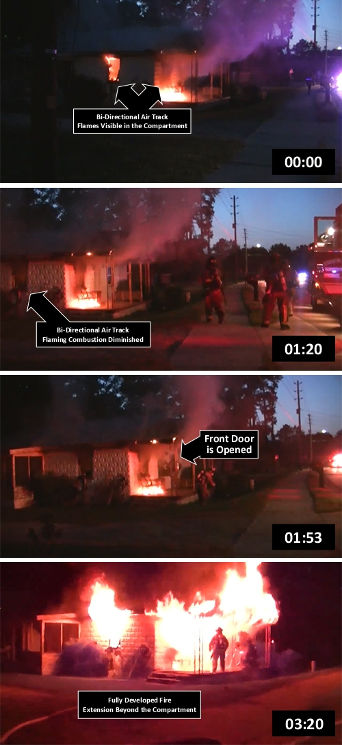
Mike Sullivan from Canada posed several related questions, focusing on a video included in the Large Vertical Vents are Good, But… post. Just to get everyone back up to speed on the video, this test was conducted by the National Institute of Standards and Technology (NIST) in Bensenville, IL. The building is a wood frame townhouse with a fire ignited on the first floor. The door on Floor 1, Side Alpha is closed and the window on Side 1, Alpha is open. The door to the second floor room where the open window is located is also open, providing a flow path between the window and the first floor fire.


Mike Asks: Although the Law of Conservation of Mass can be used to explain that for a mass of smoke to exit an equal amount of mass of oxygen must enter. But in reality is the mass of smoke inside the townhouse not an artificial mass—meaning—-typically all things in life are trying to reach an equilibrium. In this case I would think that the interior mass of smoke also elevates interior pressures and should continue exiting until an equilibrium with the exterior is met.

In the video the smoke does exit the window for quite a while. In this case if we were to discuss the Law of Conservation of Mass, would it be the mass of oxygen entering the lower part of the window that allows the smoke to exit OR with the fire burning in the living room is the mass of smoke being produced by the fire acting as a replacement for the mass of smoke exiting the window?

Both good questions! As previously discussed, smoke discharge (as well as movement on the interior) is the result of both differences in pressure and density. If considered simply from the perspective of higher pressure on the interior, smoke would discharge from the building until pressure equilibrium is reached (with the same pressure inside the building as outside). This is related to exchange of mass and energy, but only indirectly. If you opened a cylinder of compressed air, air would be discharged out of the cylinder into the atmosphere (no exchange). However, with a fire burning in the building, air must flow inward to sustain release of thermal energy, which in turn maintains (or increases) the temperature that causes the pressure increase.

Mike also had a question related to cooling of the upper layer with a solid stream, but that will be the focus of another post.

UL/NIST Video Series

Have a look at the seven part video series of Battalion Chief Derik Alkonis, LA County Fire Department; Steve Kerber, Underwriters Laboratories Firefighter Safety Research Institute, and Dan Madrzykowski, National Institute presenting on Fire Dynamics at the IAFF Redmond Firefighter Safety Symposium.

Upcoming Events

Taking Scientific Research to the Street, 2014 Fire Department Instructors Conference, April 9, 2014 at 13:30

3D Firefighting Workshop, Winkler, MB April 25 & 26, Call (204) 325-8151 to register or for more information

Tactical Integration

Tuesday, August 20th, 2013

Each of the UL ventilation studies has generated a list of tactical considerations, many of which overlap or reinforce one another. It is useful to revisit the tactical considerations developed in the horizontal ventilation study and to integrate these with those resulting from the vertical ventilation research project.

tactical_integration

Download the Tactical Integration Poster as an 11″ x 17″ PDF document and post it to stimulate discussion of the concept of tactical integration and how research with the fire service can be integrated into our standard operating guidelines, work practices, and fireground operations.

Download the Tactical Integration Worksheet provided as an 11” x 17” PDF document and work through the commonalities and differences in these two sets of tactical considerations. Also take a few minutes to think about how this information has (or should) inform your operations on the fireground.

Stay up to date with the UL Firefighter Safety Research Institute and the latest research being conducted with the fire service by connecting with the Firefighter Safety Research Institute on the web or liking them on Facebook.

Update

I am currently in Jackson Hole, Wyoming attending a Underwriters Laboratories Firefighter Safety Research Institute Advisory Board meeting and yesterday had a preview of the on-line training program focused on the results of the Study of the Effectiveness of Fire Service Vertical Ventilation and Suppression Tactics in Single Family Homes. The on-line training materials produced by the institute continue to improve, providing a higher level of interactivity and multiple paths through the curriculum. Learners can choose a short overview, the full program, or the full program with additional information for instructors that can be used to enhance training programs integrating the on-line program with classroom and hands-on instruction.

UL hopes to have the on-line vertical ventilation training program up and running within the week and I will update this post with information on how to access the course as soon as it becomes available.

Stay up to date with the UL Firefighter Safety Research Institute and the latest research being conducted with the fire service by connecting with the Firefighter Safety Research Institute on the web or liking them on Facebook.

Control the Door and Control the Fire

Thursday, July 25th, 2013

A pre-arrival video of a July 23, 2013 residential fire posted on YouTube illustrates the impact of ventilation (making an entry opening) in advance of having a hoseline in place to initiate fire attack. The outcome of increased ventilation mirrors the full scale fire tests conducted by Underwriters Laboratories (UL) during their Horizontal Ventilation Study (see The Impact of Ventilation on Fire Behavior in Legacy and Contemporary Residential Construction or the On-Line Learning Module).

Residential Fire

63 seconds after the front door is opened, the fire transitions to a fully developed fire in the compartment on the Alpha/Bravo Corner of the building and the fire extends beyond the compartment initially involved and presents a significant thermal insult to the firefighters on the hoseline while they are waiting for water.

sequence_0000_to_0320

A More Fine Grained Look

Take a few minutes to go back through the video and examine the B-SAHF (Building, Smoke, Air Track, Heat, and Flame) Indicators, tactical actions, and transitions in fire behavior.

0:00 Flames are visible through a window on Side Bravo (Alpha Bravo/Corner), burning material is visible on the front porch, and moderate smoke is issuing from Side Alpha at low velocity.

0:30 Flames have diminished in the room on the Alpha/Bravo Corner.

1:18 An engine arrives and reports a “working fire”. At this point no flames are visible in the room on the Alpha/Bravo Corner, small amount of burning material on the front porch, moderate smoke is issuing at low velocity from Side Alpha and from window on Side Bravo

1:52 A firefighter kicks in the door on Side Alpha

2:02 The firefighter who opened the door, enters the building through the Door on Side Alpha alone.

2:08 Other members of the engine company are stretching a dry hoseline to Side Bravo.

2:15 Increased in flaming combustion becomes visible through the windows on Sides A and B (Alpha/Bravo Corner).

2:31 The firefighter exits through door on Side Alpha and flaming combustion is now visible in upper area of windows on Sides A and B (Alpha/Bravo Corner).

2:49 Flames completely fill the window on Side Alpha and increased flaming combustion is visible at the upper area of the window on Side Bravo. The engine company is now repositioning the dry hoseline to the front porch

2:55 The fire in the compartment on the Alpha/Bravo Corner is now fully developed, flames completely fill the window on Side Alpha and a majority of the window on Side Bravo. Flames also begin to exit the upper area of the door on Side Alpha.

3:07 Steam or vapors are visible from the turnout coat and helmet of the firefighter working in front of the window on Side Alpha (indicating significant heat flux resulting from the flames exiting the window)

3:25 Steam or vapors are visible from the turnout coat and helmet of the firefighter on the nozzle of the dry line positioned on the front porch (also indicating significant heat flux from flaming combustion from the door, window, and under the porch roof).

3:26 The hoseline on the front porch is charged and the firefighter on the nozzle that is positioned on the front porch begins water application through the front door.

Things to Think About

There are a number of lessons that can be drawn from this video, but from a ventilation and fire control perspective, consider the following:

  • Limited discharge of smoke and flames (even when the fire has self-vented) may indicate a ventilation controlled fire.
  • Ventilation controlled fires that have already self-vented will react quickly to additional ventilation.
  • Control the door (before and after entry) until a hoseline is in place and ready to apply water on the fire
  • Application of water into the fire compartment from the exterior prior to entry reduces heat release rate and buys additional time to advance the hoseline to the seat of the fire.
  • Use of the reach of the stream from the nozzle reduces the thermal insult to firefighters and their personal protective equipment.

Also see Situational Awareness is Critical for another example of the importance of understanding practical fire dynamics and being able to apply this knowledge on the fireground.

Ed Hartin, MS, EFO, MIFireE, CFO

UL Vertical Ventilation Study
Tactical Implications

Wednesday, July 17th, 2013

Even as a member of the technical panel on the UL Vertical Ventilation Study, it will take some time to fully digest all of the data presented in the Study of the Effectiveness of Fire Service Vertical Ventilation and Suppression Tactics in Single Family Homes (Kerber, 2013). However, the tactical implications presented in this report provide an excellent starting point to understanding the influence of vertical ventilation on fire behavior and other important findings in this research project. UL will also be releasing an on-line training program in the near future that will provide a user friendly approach to exploring this information.

Read the Report and Stay up to date with the latest UL research with the fire service by connecting with the Firefighter Safety Research Institute on the web or liking them on Facebook.

vertical_quad

Tactical Implications

A number of the tactical implications identified in the vertical ventilation study replicate and reinforce those identified when UL studied the effect of horizontal ventilation. Other implications are specifically focused on vertical ventilation. The following summary examines and expands slightly on the tactical implications presented in Study of the Effectiveness of Fire Service Vertical Ventilation and Suppression Tactics in Single Family Homes (Kerber, 2013).

The Fire Environment Has Changed: While many firefighters, particularly those who have less than 15 or 20 years of service have never known a fire environment fueled by synthetic materials with rapid fire development and ventilation limited fire conditions. However, many of the tactics in use today were developed when the fire environment was quite different. Decades ago the fire environment was predominantly fueled by natural materials; fires had a lower potential heat release rate, and remained fuel controlled much longer. Changes in the fire environment require reevaluation and shift of tactics to meet these changes.

Control the Access Door: If a fire is ventilation limited, additional oxygen will increase the heat release rate. The entry point is a ventilation opening that not only allows smoke to exit, but also provides additional atmospheric oxygen to the fire, increasing heat release rate and speeding fire development. Controlling the door slows fire development and limits heat release rate. Once the fire attack crew has water on the fire and is limiting heat release by cooling the door can and should be opened as part of planned, systematic, and coordinated tactical ventilation.

Coordinated Attack Includes Vertical Ventilation: While vertical ventilation is the most efficient type of natural ventilation, it not only removes a large amount of smoke, it also introduces a large amount of air into the building (the mass of smoke and air out must equal the mass of air introduced). If uncoordinated with fire attack, the increase in oxygen will result in increased fire development and heat release. However, once fire attack is making progress, vertical ventilation will work as intended, with effective and efficient removal of smoke and replacement with fresh air.

Large Vertical Vents are Good, But… Ventilation (either horizontal or vertical) presents a bit of a paradox. Hot smoke and fire gases are removed from the building, but the fresh air introduced provides oxygen to the fire resulting in increased heat release rate. A 4’ x 8’ ventilation opening removed a large amount of hot smoke and fire gases. However, without water on the fire to reduce the heat release rate and return the fire to a fuel controlled regime, the increased air supply caused more products of combustion to be released than could be removed through the opening, overpowering the vertical vent and worsening conditions on the interior. Once fire attack returned the fire to a fuel controlled regime, the large opening was effective and conditions improved.

Location of the Vertical Vent? It Depends! The best location for a vertical ventilation opening depends on building geometry, location of the inlet(s) and resulting flow path. Often this is not known with certainty. If ventilation and fire attack are coordinated, venting over the fire provides the most efficient flow of hot smoke, fire gases, and air. However, while not mentioned in this report on vertical ventilation, working above engineered wood roof supports that are involved in fire or may have been damaged by the fire presents considerable risk. Surprisingly vertical ventilation remote from the fire provided some positive effects, but this was dependent on geometry. One of the important lessons in this tactical implication is that the effects of vertical ventilation are not only dependent on the location of the exhaust opening, but also on the location of the inlet and resulting flow paths created within the building.

Operations in the Flow Path Present Significant Risk: In UL’s tactical implication titled Stages of Fire Growth and Flow Path, Steve Kerber states “the stage of the fire (i.e. ventilation or fuel limited)”. This may be a bit confusing as the stages of fire development are typically described as ignition or incipient, growth, fully developed, and decay. Burning regime may be used to describe the conditions of fuel or ventilation controlled (although this term is used in the text 3D Firefighting, it is not as commonly used in fire dynamics literature). The location of the inlet and exhaust openings, distance between the inlet opening and the fire, shape of the inlet and exhaust openings, the interior geometry of the building and its contents all impact on flow path and the availability of oxygen for fire growth. Firefighters must consider both the upstream (between the inlet and the fire) and downstream (between the fire and the exhaust) elements of the flow path. Operations in the downstream segment of the flow path are hazardous due to the flow of hot gases and smoke, increasing convective heat transfer and potential for fire spread in this space.

Timing is (Almost) Everything: Why do we perform tactical ventilation? While firefighters can typically provide a list of potential benefits, one of the most important is to improve interior conditions for both firefighters and victims who may still be in the building. When effective tactical ventilation is coordinated with fire attack, the fire environment becomes cooler, visibility is increased, and useful flow paths are created that remove hot smoke, fire gases, and steam ahead of hoselines. However, tactical ventilation completed significantly before fire attack is having an effect on the fire can result in increased heat release rate and fire growth. Additional considerations that impact or are impacted on by timing of tactical ventilation include:

  • The fire does not react to additional air (oxygen) instantaneously
  • The higher the interior temperatures the faster the fire reacts
  • The closer the inlet opening is to the fire the faster it reacts
  • The higher the exhaust opening the faster the fire reacts
  • The more smoke exhausted from the building the more air that is introduced (the mass of air in must equal the mass of smoke and air that is exhausted)
  • The more air (oxygen) the faster the fire reacts

Reading The Fire: The UL report on vertical ventilation refers to “Reading Smoke”. While smoke is a critical category of fire behavior indicators, firefighters must consider all of the B-SAHF indicators (Building, Smoke, Air Track, Heat, and Flame) when reading the fire. The key point made in the UL vertical and horizontal ventilation reports is that nothing showing means exactly that. Nothing! As a fire becomes ventilation controlled, temperature decreases, reducing pressure in the building and as a result visible smoke indicators on the exterior often are substantially diminished or absent. When little or no smoke are observed, the fire should be treated as if it is in the ventilation limited, decay stage until proven otherwise.

Closed Doors=Increased Potential for Survival: As with UL’s horizontal ventilation experiments, the vertical ventilation experiments further demonstrated that closed doors increase victim survivability. . In each experiment a victim in the closed bedroom would have had survivable conditions and would have been able to function well through every experiment and well after the arrival of fire companies. In the bedrooms with open doors, potential victims would be unconscious if not deceased prior to fire department arrival or as a result of fire ventilation actions.

Softening the Target: In many cases, the fire has self-vented prior to the arrival of the first company (note that self-vented should not be confused with adequate, planned, systematic, and coordinated tactical ventilation). Tactical implications presented in Impact of Ventilation on Fire Behavior in Legacy and Contemporary Residential Construction (Kerber, 2010) indicated that a self-vented fire most likely will most likely be ventilation controlled and will respond quickly to any increase in ventilation.

Even with a ventilation location open the fire is still ventilation limited and will respond just as fast or faster to any additional air [oxygen]. It is more likely that the fire will respond faster because the already open ventilation location is allowing the fire to maintain a higher temperature than if everything was closed. In these cases rapid fire progression is highly probable and coordination of fire attack with ventilation becomes even more important (Kerber, 2010, p. 301).

Data on the effects of water application from the exterior during the vertical ventilation experiments reinforced the conclusions drawn from those conducted during the horizontal ventilation study. Regardless of the point of application, water quickly applied into the fire compartment improved conditions throughout the entire building. In the vertical ventilation experiments water applied from the exterior for approximately 15 seconds had a significant impact on interior conditions increasing potential for victim survivability and firefighter safety. During size-up consider the fastest and safest way to apply water to the fire. This could be by applying water through a window, through a door, from the exterior or from the interior.

You Can’t Push Fire with Water: During the vertical ventilation study, UL continued examination of the question; can water applied from a hoseline push fire? Data from this study continues to support the position that application of water does not push fire. However, discussion during the study pointed to several situations that may give the appearance of fire being pushed.

  • A flow path is changed with ventilation and not water application
  • A flow path is changed with water application
  • Turnout gear becomes saturated with energy and passes through to the firefighter
  • One room is extinguished, which allows air to entrain into another room, causing the second room to ignite or increase in burning (see Contra Costa LODD: What Happened? for an example of this phenomena)

Direct Attack is Important on Fires in Large Spaces: While large open floor plans in many modern homes presents a fire suppression challenge, open floor plans also permit application of water to burning fuel from a distance. This tactical recommendation points to the importance of using the reach of a hose stream to advantage. It is not necessary to be in the fire compartment to begin effective suppression. If an involved room is in line of sight, water can be applied to burning fuel with good effect.

Important! While not addressed in this tactical implication, the emphasis on direct attack does not diminish the importance of cooling the hot smoke and gases (fuel) in the upper layer as a control (not fire extinguishment) measure, particularly when the fire is shielded and not accessible for direct attack.

Ventilation Doctrine

Just as with door control (an anti-ventilation tactic) it is important to extend the concept of consistent doctrine to the broader context of tactical ventilation and anti-ventilation strategies and tactics. This doctrine is likely to differ based on context (e.g., building sizes and types and firefighting resources), but the fire dynamics framework will likely be quite similar. Future posts will work to examine the vertical ventilation study in more detail and to also integrate the tactical implications from this study with those from the earlier vertical ventilation study. These two important studies don’t answer all of the questions, but provide a good start.

References

Kerber, S. (2010). Impact of ventilation on fire behavior in legacy and contemporary residential construction. Retrieved July 17, 2013 from http://www.ul.com/global/documents/offerings/industries/buildingmaterials/fireservice/ventilation/DHS%202008%20Grant%20Report%20Final.pdf.

Kerber, S. (2013). Study of the effectiveness of fire service vertical ventilation and suppression tactics in single family homes. Retrieved July 17, 2013 from http://ulfirefightersafety.com/wp-content/uploads/2013/06/UL-FSRI-2010-DHS-Report_Comp.pdf

Influence of Ventilation in Residential Structures:
Tactical Implications Part 8

Friday, January 13th, 2012

The eighth and tenth tactical implications identified in the Underwriters Laboratories study of the Impact of Ventilation on Fire Behavior in Legacy and Contemporary Residential Construction (Kerber, 2011) are the answer to the question, can you vent enough and the influence of pre-existing openings or openings caused by fire effects on the speed of progression to flashover.

The ninth implication; the effects of closed doors on tenability for victims and firefighters, will be addressed in the next post.

Photo Credit: Captain Jacob Brod, Pineville (NC) Fire Department

Kerber (2011) indicates that firefighters presume that if you create enough ventilation openings that the fire will return to a fuel controlled burning regime. I am not so sure that this is the case. Until fairly recently, the concept of burning regime and influence of increased ventilation on ventilation controlled fires was not well recognized in the US fire service. However, there has been a commonly held belief that increased ventilation will improve interior conditions and reduce the potential for extreme fire behavior phenomena such as flashover. In either case, the results of the experiments conducted by UL on the influence of horizontal ventilation cast considerable doubt on the ability to accomplish either of these outcomes using horizontal, natural ventilation.

The Experiments

In order to determine the impact of increased ventilation, Kerber (2011) compared changes in temperature with varied numbers and sizes of ventilation openings. The smallest ventilation opening in the experiments conducted in both the one and two story houses was when the door on Side A was used to provide the only opening. The largest number and size of ventilation openings was in the experiments where the front door and four windows were used (see Figures 1 and 3)

The area of ventilation openings in experiments conducted in the one-story house ranged from 1.77 m2 (19.1 ft2) using the front door only to 9.51 m2 (102.4 ft2) with the front door and four windows. In the two-story house the area of ventilation openings ranged from 1.77 m2 (19.1 ft2) with front door only to 14.75 m2 (158.8 ft2) using the front door and four windows.

The most dramatic comparison is between Experiments 1 and 2 where a single opening was used (front door) and Experiments 14 and 15 where five openings were used (door and four windows).

One Story House

Experiment 1 was conducted in the one-story house using the door on Side A as the only ventilation opening. The door was opened eight minutes after ignition (480 seconds). Experiment 14 was also conducted in the one-story house, but in this case the door on Side A and four windows were used as ventilation openings. Windows in the living room and bedrooms one, two, and three were opened sequentially immediately after the door was opened, providing more than five times the ventilation area as in Experiment 1 (door only).

Figure 1. Ventilation Openings in the One-Story House

In both Experiment 1 (door only) and Experiment 14 (door and four windows), increased ventilation resulted in transition to a fully developed fire in the compartment of origin (see Figure 2). In Experiment 1, a bi-directional air track developed at the door on Side A (flames out the top and air in the bottom). In Experiment 14, a bi-directional air track is visible at all ventilation openings, with flames visible from the door and window in the Living Room on Side A and flames visible through the window in Bedroom 3. No flames extended out the ventilation openings in Bedrooms 1, 2, and 3. The upper layer in Bedroom 3 is not deep, as such there is little smoke visible exiting the window, and it appears to be serving predominantly as an inlet. On the other hand, upper layer in Bedroom 2 is considerably deeper and a large volume of thick (optically dense) smoke is pushing from the window with moderate velocity. While a bi-directional air track is evident, this window is serving predominantly as an exhaust opening.

Figure 2. Fire Conditions at 600 seconds (10:00)

As illustrated in Figure 3, increased ventilation resulted in a increase in heat release rate and subsequent increase in temperature. It is important to note that the peak temperature in Experiment 14 (door and four windows) is more than 60% higher than in Experiment 1 (door only).

Figure 3. Living Room Temperature 0.30 m(1’) Above the Floor One-Story House

Note. Adapted from Impact of Ventilation on Fire Behavior in Legacy and Contemporary Residential Construction (p. 298), by Steve Kerber, 2011, Northbrook, IL: Underwriters Laboratories.

Based on observed conditions and temperature measurement within the one-story house, it is evident that increasing the ventilation from 1.77 m2 (19.1 ft2) using the front door to 9.51 m2 (102.4 ft2) with the front door and four windows did not return the fire to a fuel controlled burning regime and further, did not improve interior conditions.

It is important to note that these experiments were conducted without coordinated fire control operations in order to study the effects of ventilation on fire behavior. Conditions changed quickly in both experiments, but the speed with which the fire transitioned from decay to growth and reached flashover was dramatically more rapid with a larger ventilation area (i.e., door and four windows).

Two Story House

Experiment 2 was conducted in the two-story house using the door on Side A as the only ventilation opening. The door was opened ten minutes after ignition (600 seconds). Experiment 15 was also conducted in the two-story house, but in this case the door on Side A and four windows were used as ventilation openings. One window in the Living Room (Floor 1, Side A, below Bedroom 3) Den (Floor 1, Side C, below Bedroom 2) and two windows in the Family Room (Side C) were opened sequentially immediately after the door was opened, providing more than eight times the ventilation area as in Experiment 2 (door only).

Figure 4. Ventilation Openings in the Two-Story House

In both Experiment 2 (door only) and Experiment 15 (door and four windows), increased ventilation resulted in transition to a fully developed fire in the compartment of origin. Flames were seen from the family room windows in Experiment 15 (see Figure 5). However, in Experiment 2, no flames were visible on the exterior (due to the distance between the fire compartment and ventilation opening) and a bi-directional air track developed at the door on Side A (smoke out the top and air in the bottom). In Experiment 15, a bi-directional air track is visible at all ventilation openings, with flames visible from the windows in the family room on Side C. No flames extended out the ventilation openings on Side A or from the Den on Side C (see Figure 5). The upper layer is extremely deep (particularly considering the ceiling height of 16’ in the family room and foyer atrium. The velocity of smoke discharge from ventilation openings is moderate.

Figure 5. Fire Conditions at 780 seconds (13:00)

As illustrated in Figure 6, increased ventilation resulted in a increase in heat release rate and subsequent increase in temperature. It is important to note that the peak temperature in Experiment 15 (door and four windows) is approximately 50% higher than in Experiment 2 (door only).

Figure 6. Living Room Temperature 0.30 m(1’) Above the Floor One-Story House

Note. Adapted from Impact of Ventilation on Fire Behavior in Legacy and Contemporary Residential Construction (p. 299), by Steven Kerber, 2011, Northbrook, IL: Underwriters Laboratories.

Another Consideration

Comparison of these experiments answers the questions if increased horizontal ventilation would 1) return the fire to a fuel controlled state or 2) improve interior conditions. In a word, no, increased horizontal ventilation without concurrent fire control simply increased the heat release rate (sufficient for the fire to transition through flashover to a fully developed stage) in the involved compartment.

Examining thermal conditions in other areas of the building also provides an interesting perspective on these two sets of experiments. Figure 7 illustrates temperatures at 0.91 m (3’) during Experiment 1 (door only) and Experiment 14 (door and four windows) in the one-story house.

Figure 7. Temperatures at 0.91 m (3’) during Experiments 1 and 14

Note. Adapted from Impact of Ventilation on Fire Behavior in Legacy and Contemporary Residential Construction (p. 99, p. 162), by Steven Kerber, 2011, Northbrook, IL: Underwriters Laboratories.

Thermal conditions not only worsened in the fire compartment, but also along the flow path (for a more detailed discussion of flow path, see UL Tactical Implications Part 7) and in downstream compartments. Temperature in the hallway increased from a peak of just over 200o C to approximately 900o C when ventilation was increased by opening the four additional windows.

Unplanned Ventilation

Each of the experiments in this study were designed to examine the impact of tactical ventilation when building ventilation was limited to normal leakage and fire conditions are ventilation controlled (decay stage). In each of these experiments, increased ventilation resulted in a rapid increase in heat release rate and temperature. Even when ventilation was increased substantially (as in Experiments 14 and 15), it was not possible to return the fire to a fuel controlled burning regime.

It is also possible that a door or window will be left open by an exiting occupant or that the fire may cause window glazing to fail. The impact of these types of unplanned ventilation will have an effect on fire development. Creation of an opening prior to the fire reaching a ventilation controlled burning regime will potentially slow fire progression. However, on the flip side, providing an increased oxygen supply will allow the fire to continue to grow, potentially reaching a heat release rate that will result in flashover. If the opening is created after the fire is ventilation controlled, the results would be similar to those observed in each of these experiments. When the fire is ventilation controlled, increased ventilation results in a significant and dramatic increase in heat release rate and worsening of thermal conditions inside the building.

If the fire has self-ventilated or an opening has been created by an exiting occupant, the increased ventilation provided by creating further openings without concurrent fire control will result in a higher heat release rate than if the openings were not present and will likely result in rapid fire progression.

What’s Next?

I will be at UL the week after next and my next post will provide an update on UL’s latest research project examining the influence of vertical ventilation on fire behavior in legacy and contemporary residential construction.

Two tactical implications from the horizontal ventilation study remain to be examined in this series of posts: the impact of closed doors on tenability and the interesting question can you push fire with stream from a hoseline?

The last year has presented a challenge to maintaining frequency of posts to the CFBT Blog. However, I am renewing my commitment to post regularly and will be bringing back Reading the Fire, continuing examination of fundamental scientific concepts, and integration of fire control and ventilation tactics.

References

Kerber, S. (2011). Impact of ventilation on fire behavior in legacy and contemporary residential construction. Retrieved July 16, 2011 from http://www.ul.com/global/documents/offerings/industries/buildingmaterials/fireservice/ventilation/DHS%202008%20Grant%20Report%20Final.pdf

Influence of Ventilation in Residential Structures:
Tactical Implications Part 7

Wednesday, November 9th, 2011

The seventh tactical implication identified in the Underwriters Laboratories study of the Impact of Ventilation on Fire Behavior in Legacy and Contemporary Residential Construction (Kerber, 2011) is the influence of changes in ventilation on flow path.

“Every new ventilation opening provides a new flow path to the fire and vice versa. This could create very dangerous conditions when there is a ventilation limited fire” (Kerber, 2011).

Air Track and Flow Path

Air track and flow path are closely related and provide an excellent framework for understanding the influence of changes in ventilation on fire development and flow path.

Air Track: Closely related to flow path, air track is the movement of air and smoke as observed from the exterior and inside the structure. Air track is used to describe a group of fire behavior indicators that includes direction of smoke movement at openings (e.g., outward, inward, pulsing), velocity and turbulence, and movement of the lower boundary of the upper layer (e.g., up, down, pulsing).

Observation of air track indicators may provide clues as to the potential flow path of air and hot gases inside the fire building. As discussed in previous posts in this series (Part 1, Part 2, Part 3, Part 4, Part 5, Part 6), movement of air to the fire has a major impact on fire development. Movement of hot gases away from the fire is equally important!

Flow Path: In a compartment fire, flow path is the course of movement hot gases between the fire and exhaust openings and the movement of air towards the fire.

Both of these components of flow path are important! Movement of hot gases between the fire an exhaust openings is a major factor in heat transfer outside the compartment of origin and presents a significant thermal threat to occupants and firefighters. When the fire is in a ventilation controlled burning regime, movement of air from to the fire provides the oxygen necessary for fire growth and increased heat release rate (impacting on conditions in the flow path downstream from the fire.

Flow path can significantly influence fire spread and the hazard presented to occupants and firefighters.

Reading the Fire

Before engaging in the meat of this UL Tactical Implication, quickly review essential air track indicators used in the Building, Smoke, Air Track, Heat, and Flame (B-SAHF) fire behavior indicators organizing scheme.

Figure 1. Air Track Indicators

As illustrated in Figure 1, key indicators include wind direction and velocity (consider this before you even arrive on-scene), directions in which the air and smoke are moving, and the velocity and flow of smoke and air movement.

Take a look at Figure 2. Consider all of the B-SAHF indicators, but pay particular attention to Air Track. What is the current flow path? How might the flow path change if one or more windows on Floor 2 Side A are opened prior to establishing fire control?

Figure 2. Residential Fire in a 1 ½ Story Wood Frame Dwelling

Photo courtesy of Curt Isakson, County Fire Tactics

UL Focus on Flow Path

Tactical implications related to flow path identified in Impact of Ventilation on Fire Behavior in Legacy and Contemporary Residential Construction (Kerber, 2011) focus on creation of additional openings and changes in flow path as a result of “crews venting as the go” (p. 296). This is only one issue related to flow path!

The UL experiments showed that increasing the number of flow paths resulted in higher peak temperatures, a faster transition from decay to growth stage and more rapid transition to flashover. However, this is not the only hazard!

As previously discussed in the series of posts examining the fire in a Washington DC townhouse that took the lives of Firefighters Anthony Phillips and Louis Matthews, operating in the flow path presents potential for significant thermal hazard.

In this incident, the initial attack crew was operating on the first floor of a two-story townhouse with a daylight basement. When crews opened the sliding glass doors in the basement (on Side C), a flow path was created between the opening at the basement level on Side C, up an open interior stairway to the first floor, and out the first floor doorway (on Side A). Firefighters working in this flow path were subjected to extreme thermal stress, resulting in burns that took the lives of Firefighters Phillips and Mathews and serious injuries to another firefighter.

Figure 1. Perspective View of 3146 Cherry Road and Location of Slices

Note: From Simulation of the Dynamics of the Fire at 3146 Cherry Road NE Washington D.C., May 30, 1999, NISTR 6510 (p. 15) by Dan Madrzykowski and Robert Vettori, 2000, Gaithersburg, MD: National Institute for Standards and Technology.

Figure XX illustrates thermal conditions, velocity and oxygen concentration at various locations within the flow path.

Figure 10. Perspective Cutaway, Flow/Temperature, Velocity, and O2 Concentration

The temperature of the atmosphere (i.e., smoke and air) is a significant concern in the fire environment, and firefighters often wonder or speculate about how hot it was in a particular fire situation. However, gas temperature in the fire environment is a bit more complex than it might appear on the surface and is only part of the thermal hazard presented by compartment fire.

Convective heat transfer is influenced by gas temperature and velocity. When hot gases are not moving or the flow of gases across a surface (such as your body or personal protective equipment) is slow, energy is transferred from the gases to the surface (lowering the temperature of the gases, while raising surface temperature). These lower temperature gases act as an insulating layer, slowing heat transfer from higher temperature gases further away from the surface. When velocity increases, cooler gases (which have already transferred energy to the surface) move away and are replaced by higher temperature gases. When velocity increases sufficiently to result in turbulent flow, hot gases remain in contact with the surface on a relatively constant basis, increasing convective heat flux.

For a more detailed discussion of this incident and the influence of radiative and convective heat transfer in the flow path, see the prior posts on the Washington DC Townhouse Fire Case Study.

Wind Driven Fires & Flow Path

While operating in the flow path presents serious risk, when fire behavior is influenced by wind, conditions in the flow path can be even more severe. In experiments conducted by the National Institute of Standards and Technology (NIST) demonstrated that under wind driven conditions, both temperature and heat flux, which were twice as high in the “flow” portion of the corridor as opposed to the “static” portion of the corridor (where there was no flow path). See the previous posts on Wind Driven Fires for more information on flow path hazards under wind driven conditions:

Discussion

The sixth and seventh tactical implications identified in the UL Horizontal Ventilation Study are interrelated and can be expanded to include the following key points:

  • Heat transfer (convective and radiative) is greatest along the flow path between the fire and exhaust opening.
  • Exhaust openings located higher than the fire will increase the velocity of gases along the flow path (further increasing convective heat transfer).
  • Flow of hot gases from the fire to an exhaust opening is significantly influenced by air flow from inlet openings to the fire (the greater the inflow of air, the higher the heat release rate and flow of hot gases to the exhaust opening).
  • Flow path can be created by a single opening that serves as both inlet and exhaust (such as an open door or window).
  • Thermal conditions in the flow path can quickly become untenable for both civilian occupants and firefighters. As noted in an earlier NIST Study examining wind driven fires, under wind driven conditions this change can be extremely rapid.
  • Closing an inlet, exhaust opening, or introducing a barrier (such as a closed door) in the flow path slows gas flow and reduces the hazard downstream from the barrier.
  • When the fire is ventilation controlled, limiting inflow of air (e.g., door control) can slow the increase in heat release rate and progression to a growth stage fire.
  • Multiple openings results in multiple flow paths and increased air flow to the fire, resulting in more rapid fire development and increased heat release rate.

What’s Next?

The next tactical implication identified in the UL Horizontal Ventilation study examines an interesting question: Can you vent enough (to return the fire to a fuel controlled burning regime)? This question may also be restated as can you perform sufficient natural horizontal ventilation to improve internal conditions. The answer to this question will likely be extended through the Vertical Ventilation Study that will be conducted by UL in early 2012!

References

District of Columbia (DC) Fire & EMS. (2000). Report from the reconstruction committee: Fire at 3146 Cherry Road NE, Washington DC, May 30, 1999. Washington, DC: Author.

Kerber, S. (2011). Impact of ventilation on fire behavior in legacy and contemporary residential construction. Retrieved July 16, 2011 from http://www.ul.com/global/documents/offerings/industries/buildingmaterials/fireservice/ventilation/DHS%202008%20Grant%20Report%20Final.pdf

Madrzykowski, D. & Kerber, S. (2009). Fire Fighting Tactics Under Wind Driven Conditions. Retrieved (in four parts) February 28, 2009 from http://www.nfpa.org/assets/files//PDF/Research/Wind_Driven_Report_Part1.pdf; http://www.nfpa.org/assets/files//PDF/Research/Wind_Driven_Report_Part2.pdf;http://www.nfpa.org/assets/files//PDF/Research/Wind_Driven_Report_Part3.pdf;http://www.nfpa.org/assets/files//PDF/Research/Wind_Driven_Report_Part4.pdf.

Madrzykowski, D. & Vettori, R. (2000). Simulation of the Dynamics of the Fire at 3146 Cherry Road NE Washington D.C., May 30, 1999, NISTR 6510. August 31, 2009 from http://fire.nist.gov/CDPUBS/NISTIR_6510/6510c.pdf

National Institute for Occupational Safety and Health (NIOSH). (1999). Death in the line of duty, Report 99-21. Retrieved August 31, 2009 from http://www.cdc.gov/niosh/fire/reports/face9921.html


Influence of Ventilation in Residential Structures: Tactical Implications Part 5

Thursday, September 8th, 2011

The fifth tactical implication identified in the Underwriters Laboratories study of the Impact of Ventilation on Fire Behavior in Legacy and Contemporary Residential Construction (Kerber, 2011) is described as failure of the smoke layer to lift following horizontal natural ventilation and smoke tunneling and rapid air movement in through the front door.

In the experiments conducted by UL, both the single and two story dwellings filled rapidly with smoke with the smoke layer reaching the floor prior to ventilation. This resulted in zero visibility throughout the interior (with the exception of the one bedroom with a closed door). After ventilation, the smoke layer did not lift (as many firefighters might anticipate) as the rapid inward movement of air simply produced a tunnel of clear space just inside the doorway.

Put in the context of the Building, Smoke, Air Track, Heat, and Flame (B-SAHF) fire behavior indicators, these phenomena fit in the categories of smoke and air track. Why did these phenomena occur and what can firefighters infer based on observation of these fire behavior indicators?

Smoke Versus Air Track

There are a number of interrelationships between Smoke and Air Track. However, in the B-SAHF organizing scheme they are considered separately. As we begin to develop or refine the map of Smoke Indicators it is useful to revisit the difference between these two categories in the B-SAHF scheme.

Smoke: What does the smoke look like and where is it coming from? This indicator can be extremely useful in determining the location and extent of the fire. Smoke indicators may be visible on the exterior as well as inside the building. Don’t forget that size-up and dynamic risk assessment must continue after you have made entry!

Air Track: Related to smoke, air track is the movement of both smoke (generally out from the fire area) and air (generally in towards the fire area). Observation of air track starts from the exterior but becomes more critical when making entry. What does the air track look like at the door? Air track continues to be significant when you are working on the interior.

Smoke Indicators

There are a number of smoke characteristics and observations that provide important indications of current and potential fire behavior. These include:

  • Location: Where can you see smoke (exterior and interior)?
  • Optical Density (Thickness): How dense is the smoke? Can you see through it? Does it appear to have texture like velvet (indicating high particulate content)?
  • Color: What color is the smoke? Don’t read too much into this, but consider color in context with the other indicators.
  • Physical Density (Buoyancy): Is the smoke rising, sinking, or staying at the same level?
  • Thickness of the Upper Layer: How thick is the upper layer (distance from the ceiling to the bottom of the hot gas layer)?

As discussed in Reading the Fire: Smoke Indicators Part 2, these indicators can be displayed in a concept map to show greater detail and their interrelationships (Figure 1).

Figure 1. Smoke Indicators Concept Map

Air Track

Air track includes factors related to the movement of smoke out of the compartment or building and the movement of air into the fire. Air track is caused by pressure differentials inside and outside the compartment and by gravity current (differences in density between the hot smoke and cooler air). Air track indicators include velocity, turbulence, direction, and movement of the hot gas layer.

  • Direction: What direction is the smoke and air moving at specific openings? Is it moving in, out, both directions (bi-directional), or is it pulsing in and out?
  • Wind: What is the wind direction and velocity? Wind is a critical indicator as it can mask other smoke and air track indicators as well as serving as a potentially hazardous influence on fire behavior (particularly when the fire is in a ventilation controlled burning regime).
  • Velocity & Flow: High velocity, turbulent smoke discharge is indicative of high temperature. However, it is essential to consider the size of the opening as velocity is determined by the area of the discharge opening and the pressure. Velocity of air is also an important indicator. Under ventilation controlled conditions, rapid intake of air will be followed by a significant increase in heat release rate.

As discussed in Reading the Fire: Air Track Indicators Part 2, these indicators can be displayed in a concept map to show greater detail and their interrelationships (Figure 2).

Figure 2. Air Track Indicators Concept Map

air t

Discharge of smoke at openings and potential openings (Building Factors) is likely the most obvious indicator of air track while lack of smoke discharge may be a less obvious, but equally important sign of inward movement of air. Observation and interpretation of smoke and air movement at openings is an essential part of air track assessment, but it must not stop there. Movement of smoke and air on the interior can also provide important information regarding fire behavior.

An Ongoing Process

Reading the fire is an ongoing process, beginning with reading the buildings in your response area prior to the incident and continuing throughout firefighting operations. It is essential to not only recognize key indicators, but to also note changing conditions. This can be difficult when firefighters and officer are focused on the task at hand.

UL Experiment 13

This experiment examined the impact of horizontal ventilation through the door on Side A and one window as high as possible on Side C near the seat of the fire. The family room was the fire compartment. This room had a high (two-story) ceiling with windows at ground level and the second floor level (see Figure 3).

Figure 3. Two-Story Dwelling

In this experiment, the fire was allowed to progress for 10:00 after ignition, at which point the front door (see Figure 3) was opened to simulate firefighters making entry. Fifteen seconds after the front door was opened (10:15), an upper window in the family room (see Figure 3) was opened. No suppression action was taken until 12:28, at which point a 10 second application of water was made through the window on Side C using a straight stream from a combination nozzle.

As with all the other experiments in this series fire development followed a consistent path. The fire quickly consumed much of the available oxygen inside the building and became ventilation controlled. At oxygen concentration was reduced, heat release rate and temperature within the building also dropped. Concurrently, smoke and air track indicators visible from the exterior were diminished. Just prior to opening the door on Side A, there was little visible smoke from the structure (see Figure 4).

Figure 4. Experiment 13 at 00:09:56 (Prior to Ventilation)

As illustrated in Figure 5, a bi-directional air track was created when the front door was opened. Hot smoke flowed out the upper area of the doorway while air pushed in the bottom creating a tunnel of clear space inside the doorway (but no generalized lifting of the upper layer.

Figure 5. Experiment 13 at 00:10:14 (Door Open)

As illustrated in Figure 6, opening the upper level window in the family room resulted in a unidirectional air track flowing from the front door to the upper level window in the family room. No significant exhaust of smoke can be seen at the front door, while a large volume of smoke is exiting the window. However, while the tunneling effect at floor level was more pronounced (visibility extended from the front door to the family room), there was no generalized lifting of the upper layer throughout the remainder of the building.

Figure 6. Experiment 13 at 00:10:21 (Door and Window Open)

With the increased air flow provided by ventilation through the door on Side A and Window at the upper level on Side C, the fire quickly transitioned to a fully developed stage in the family room. The heat release rate (HRR) and smoke production quickly exceeded the limited ventilation provided by these two openings and the air track at the front door returned to bi-directional (smoke out at the upper level and air in at the lower level) as shown in Figure 7.

Figure 7. Experiment 13 at 00:11:22 (Door and Window Open)

What is the significance of this observation? Movement of smoke out the door (likely the entry point for firefighters entering for fire attack, search, and other interior operations) points to significant potential for flame spread through the upper layer towards this opening. The temperature of the upper layer is hot, but flame temperature is even higher, increasing the radiant heat flux (transfer) to crews working below. Flame spread towards the entry point also has the potential to trap, and injure firefighters working inside.

Gas Velocity and Air Track

A great deal can be learned by examining both the visual indicators illustrated in Figures 4-7 and measurements taken of gas velocity at the front door. During the ventilation experiments conducted by UL, gas velocities were measured at the front door and at the window used for ventilation (see Figure 3). Five bidirectional probes were placed in the doorway at 0.33 m (1’) intervals. Positive values show gas movement out of the building while negative values show inward gas movement. In order to provide a simplified view of gas movement at the doorway, Figure 8 illustrates gas velocity 0.33 m (1’) below the top of the door, 0.33 m (1’) from the bottom of the door, and 0.66 m (2’) above the bottom of the door.

A bidirectional (out at the top and in at the bottom) air track developed at the doorway before the door was opened (see Figure 8) as a result of leakage at this opening. It is interesting to note variations in the velocity of inward movement of air from the exterior of the building, likely a result of changes in combustion as the fire became ventilation controlled. The outward flow at the upper level resulted in visible smoke on the exterior of the building. While not visible, inward movement of air was also occurring (as shown by measurement of gas velocity at lower levels in the doorway.

Creation of the initial ventilation opening by opening the front door created a strong bidirectional air track with smoke pushing out the top of the door while air rapidly moved in the bottom. Had the door remained the only ventilation opening, this bidirectional flow would have been sustained (as it was in all experiments where the door was the only ventilation opening).

Opening the upper window in the family room resulted in a unidirectional flow inward through the doorway. However, this phenomenon was short lived, with the bidirectional flow reoccurring in less than 60 seconds. This change in air track resulted from increased heat release rate as additional air supply was provided to the fire in the family room.

Figure 8. Front Door Velocities

Note: Adapted from Impact of Ventilation on Fire Behavior in Legacy and Contemporary Residential Construction (p. 243), by Stephen Kerber, Northbrook, IL: Underwriters Laboratories, 2011.

While not the central focus of the UL research, these experiments also examined the effects of exterior fire stream application on fire conditions and tenability. Each experiment included a 10 second application with a straight stream and a 10 second application of a 30o fog pattern. Between these two applications, fire growth was allowed to resume for approximately 60 seconds.

The straight stream application resulted in a reduction of temperature in the fire compartment and adjacent compartments (where there was an opening to the family room or hallway) as water applied through the upper window on Side C (ventilation opening) cooled the compartment linings (ceiling and opposite wall) and water deflected off the ceiling dropped onto the burning fuel. As the stream was applied, air track at the door on Side A changed from bidirectional to unidirectional (inward). This is likely due to the reduction of heat release rate achieved by application of water onto the burning fuel with limited steam production.

When the fog pattern was applied, there was also a reduction of temperature in the fire compartment and adjacent compartments (where there was an opening in the family room or hallway) as water was applied through the upper window on Side C (ventilation opening) cooled the upper layer, compartment linings, and water deflected off the ceiling dropped onto the burning fuel. The only interconnected area that showed a brief increase in temperature was the ceiling level in the dining room. However, lower levels in this room showed an appreciable drop in temperature. Air track at the door on Side A changed from bidirectional to unidirectional (outward) when the fog stream was applied. This effect is likely due to air movement inward at the window on Side C and the larger volume of steam produced on contact with compartment linings as a result of the larger surface area of the fog stream.

The effect of exterior streams will be examined in more detail in a subsequent post.

Important Lessons

The fifth tactical implication identified in the Underwriters Laboratories study of the Impact of Ventilation on Fire Behavior in Legacy and Contemporary Residential Construction (Kerber, 2011) is described as failure of the smoke layer to lift following horizontal natural ventilation and smoke tunneling and rapid air movement in through the front door.

Additional lessons that can be learned from this experiment include:

  • Ventilating horizontally at a high point results in higher flow of both air and smoke.
  • Increased inward air flow results in a rapid increase in heat release rate.
  • The rate of fire growth quickly outpaced the capability of the desired exhaust opening, returning the intended inlet to a bi-directional air track (potentially placing firefighters entering for fire attack or search at risk due to rapid fire spread towards their entry point).

Tactical applications of this information include:

  • Ensure that the attack team is in place with a charged line and ready to (or has already) attack the fire (not simply ready to enter the building) before initiating horizontal ventilation.
  • Cool the upper layer any time that it is above 100o C (212o F) to reduce radiant and convective heat flux and to limit potential for ignition and flaming combustion in the upper layer.

Note that this research project did not examine the impact of gas cooling, but examination of the temperatures at the upper levels in this experiment (and others in this series) point to the need to cool hot gases overhead.

What’s Next?

I am on the hunt for videos that will allow readers to apply the tactical implications of the UL study that have been examined to this point in conjunction with the B-SAHF fire behavior indicators. My next post will likely provide an expanded series of exercises in Reading the Fire.

The next tactical implication identified in the UL study (Kerber, 2011) examines the hazards encountered during Vent Enter Search (VES) tactical operations. A subsequent post will examine this tactic in some detail and explore this tactical implication in greater depth.

References

Kerber, S. (2011). Impact of ventilation on fire behavior in legacy and contemporary residential construction. Retrieved July 16, 2011 from http://www.ul.com/global/documents/offerings/industries/buildingmaterials/fireservice/ventilation/DHS%202008%20Grant%20Report%20Final.pdf

UL Ventilation Course

Saturday, December 18th, 2010

Impact of Ventilation on Fire Behavior

Earlier this year, Underwriters Laboratories (UL) conducted a series of full-scale experiments to determine the influence of ventilation on fire behavior in legacy and contemporary residential construction (see Did You Ever Wonder?).

UL University recently releases an on-line training program based on this research. Impact of Ventilation on Fire Behavior in Legacy and Contemporary Residential Construction is an excellent examination of the influence of ventilation on fire behavior and discussion of the tactical implications of the lessons learned through this research.

Every Firefighter and Fire Officer should complete
this training program within the next 30 days!

Completion of this on-line program could be the most important 90 minutes of training that you complete in the next year! I do not make this statement lightly. Understanding the relationship between ventilation and fire behavior is a critical competency for firefighters and fire officers.

After completing this on-line training program, consider the following questions and discuss them with the firefighters and fire officers you work with:

  • What are the indicators of a ventilation controlled fire?
  • How do your forcible entry and door entry procedures influence fire behavior?
  • How do you (or do you) coordinate fire attack and ventilation? How can tactical coordination be improved in your department?
  • What hazards are presented when performing VES (Vent, Enter, & Search) under ventilation controlled conditions? How can these hazards be mitigated?
  • What influence do closed doors have on the survivability profile (for either civilian occupants or trapped firefighters)?
  • What other lessons can you draw from this important research?

Research Report

In addition to the on-line course, UL has published a comprehensive report on this important research projects: Impact of Ventilation on Fire Behavior in Legacy and Contemporary Residential Construction.

Video

You can also download an excellent video illustrating the difference between fuel characteristics and loading in legacy and contemporary residential occupancies. This video is a tremendous tool to illustrate changes in the built environment to both firefighters and civilian audiences.

High Resolution Video

Low Resolution Video

Lima Backdraft

I am still working the report on my staff ride to the site of the 1997 backdraft at Luis Giribaldi Street and 28 de Julio Street in the Victoria section of Lima, Peru and should have it posted within the next week.

Ed Hartin, MS, EFO, MIFireE, CFO

Did You Ever Wonder?

Thursday, December 24th, 2009

The ability to read the fire and predict likely fire behavior is a critical skill for both firefighters and fire officers. Previous posts have examined how to use the B-SAHF scheme to recognize critical fire behavior indicators and identify the stage of fire development, burning regime, and potential for extreme fire behavior such as flashover or backdraft. However, there is something missing!

Experience is critical to adapting standard procedures and practices to a complex and dynamic operational environment. However, learning about fire behavior and changes in fire conditions based on fireground observations are a bit like a black box test. Black box testing is a technique for testing computer software in which the internal workings of the item being tested are not known by the tester. This is not entirely true in the case of fire behavior, but there is much that we dont know when assessing conditions on the fireground. How long has the fire been burning? What are the specific characteristics of the fuel? What sort of internal compartmentation is present? What exactly is the ventilation profile? Some of these factors can be determined during fire investigation and it is also possible to determine (with some degree of uncertainty) what influence these factors had on the outcome of the incident. Did you ever wonder how fire behavior would have changed if you had used different tactics? Unfortunately, in real life there are no do overs!

UL Tactical Ventilation Research Project

One of the people who has asked himself the question of what would have changed if different tactics were used is Underwriters Laboratories Fire Protection Engineer Steve Kerber.

Underwriters Laboratories (UL) has received a Firefighter Safety Research and Development Grant from the Department of Homeland Security (DHS). This research project will investigate and analyze the impact of natural horizontal ventilation on fire development and conditions in legacy (older, more highly compartmented) and contemporary (multi-level, open floor plan) residential structures.

Preliminary work has included review of literature related to horizontal ventilation and incidents in which ventilation had a significant influence on firefighter injuries and fatalities. In addition, UL has done preliminary work on the performance of various structural components such as single and multi-pane windows as preliminary input for design of full scale residential fire experiments.

In mid-December 2009, Steve Kerber met with the project advisory panel comprised of Captain Charles Bailey, Montgomery County (MD) Fire Department; Lieutenant John Ceriello New York City Fire Department, Firefighter James Dalton and Director of Training Richard Edgeworth, Chicago Fire Department, Chief Ed Hartin, Central Whidbey Island (WA) Fire & Rescue, Chief Otto Huber Loveland-Symmes (OH) Fire Department, and Chief Mark Nolan, Northbrook (IL) Fire Department. In addition, the advisory panel includes Fire Protection Engineers Dan Madrzykowski from the National Institute of Standards and Technology (NIST) and Dr. Stefan Svensson, a research and development engineer from the Swedish Civil Contingencies Agency.

Figure 1. Defining Experiment Parameters for the Contemporary Structure

kerber_plans

The main task presented to the advisory panel at the first meeting was to aid in defining the parameters for the experiment; including fire location, changes in ventilation profile, timing of these changes, and instrumentation to measure effects on fire development and conditions.

UL Large Fire Research Facility

The ventilation experiments will be conducted at the UL Large Fire Research Facility in Northbrook, IL. From the exterior, this facility simply looks like a large industrial building (see Figure 2). However, the interior of the structure includes a unique facility for fire research.

Figure 2. UL Large Fire Research Facility

ul_large_fire_lab_outside

One of the facilities inside this building is a 100 x 120 (30.48 m x 36.58 m) with a ceiling height that is adjustable up to 50 (15.24 m) (see Figure 3). All of the smoke resulting from tests in this facility is exhausted through a system designed to oxidize unburned fuel and scrub hazardous products from the effluent prior to discharge to the atmosphere. Tests are monitored from a control room that overlooks the large burn room.

Figure 3. Large Burn Room

ul_large_fire_lab_inside

Over the next month, the two residential structures to be used for the ventilation experiments will be constructed inside the large burn room at the UL Large Fire Test Facility. After construction is complete, a series of 16 full scale fire experiments is planned to evaluate a range of different horizontal ventilation scenarios.

Research with the Fire Service

Steve Kerber has often stated that it is essential that scientists and engineers conduct research with, not for, the fire service. Engagement between researchers and firefighters on the street is essential in advancement of our profession. With this ventilation research project, Underwriters Laboratories is actively engaged in this process.

The outcome of this project will not simply be an academic paper (but there might be one or more of those as well). As part of the DHS grant, UL will be developing an on-line course to present the results of the experiments and their practical application on the fireground.

Happy Holidays,

Ed Hartin, MS, EFO, MIFireE, CFO

Townhouse Fire: Washington, DC
What Happened

Monday, September 14th, 2009

This post continues study of an incident that resulted in two line-of-duty deaths as a result of extreme fire behavior in a townhouse style apartment building in Washington, DC.

A Quick Review

The previous post in this series, Fire Behavior Case Study of a Townhouse Fire: Washington, DC examined building construction and configuration that had a significant impact on the outcome of this incident. The fire occurred in the basement of a two-story, middle of building, townhouse style apartment with a daylight basement. This configuration provided an at grade entrance to the Floor 1 on Side A and an at grade entrance to the Basement on Side C.

The fire originated in an electrical junction box attached to a fluorescent light fixture in the basement ceiling (see Figures 1 and 2). The occupants of the unit were awakened by a smoke detector. The female occupant noticed smoke coming from the floor vents on Floor 2. She proceeded downstairs and opened the front door and then proceeded down the first floor hallway towards Side C, but encountered thick smoke and high temperature. The female and male occupants exited the structure, leaving the front door open, and made contact with the occupant of an adjacent unit who notified the DC Fire & EMS Department at 0017 hours.

Dispatch Information

At 00:17, DC Fire & EMS Communications Division dispatched a first alarm assignment consisting of Engines 26, 17, 10, 12, Trucks 15, 4, Rescue Squad 1, and Battalion 1 to 3150 Cherry Road NE. At 0019 Communications received a second call, reporting a fire in the basement of 3146 Cherry Road NE. Communications transmitted the update with the change of address and report of smoke coming from the basement. However, only one of the responding companies (Engine 26) acknowledged the updated information.

Weather Conditions

Temperature was approximately 66o F (19o C) with south to southwest winds at 5-10 mi/hr (8-16 km/h), mostly clear with no precipitation.

Conditions on Arrival

Approaching the incident, Engine 26 observed smoke blowing across Bladensburg Road. Engine 26 arrived at a hydrant at the corner of Banneker Drive and Cherry Road at 00:22 hours and reported smoke showing. A short time later, Engine 26 provided an updated size-up with heavy smoke showing from Side A of a two story row house. Based on this report, Battalion 1 ordered a working fire dispatch and a special call for the Hazmat Unit at 00:23. This added Engine 14, Battalion 2, Medic 17 and EMS Supervisor, Air Unit, Duty Safety Officer, and Hazmat Unit.

Firefighting Operations

DC Fire and EMS Department standard operating procedures (SOP) specify apparatus placement and company assignments based on dispatch (anticipated arrival) order. Note that dispatch order (i.e., first due, second due) may de different than order of arrival if companies are delayed by traffic or are out of quarters.

Standard Operating Procedures

Operations from Side A

The first due engine lays a supply line to Side A, and in the case of basement fires, the first line is positioned to protect companies performing primary search on upper floors by placing a line to cover the interior stairway to the basement. The first due engine is backed up by the third due engine. The apparatus operator of the third due engine takes over the hydrant and pumps supply line(s) laid by the first due engine, while the crew advances a backup line to support protection of interior exposures and fire attack from Side A.

The first due truck takes a position on Side A and is responsible for utility control and placement of ladders for access, egress, and rescue on Side A. If not needed for rescue, the aerial is raised to the roof to provide access for ventilation.

The rescue squad positions on Side A (unless otherwise ordered by Command) and is assigned to primary search using two teams of two. One team searches the fire floor, the other searches above the fire floor. The apparatus operator assists by performing forcible entry, exterior ventilation, monitoring search progress, and providing emergency medical care as necessary.

Operations from Side C

The second due engine lays a supply line to the rear of the building (Side C), and in the case of basement fires, is assigned to fire attack if exterior access to the basement is available and if it is determined that the first and third due engines are in a tenable position on Floor 1. The second due engine is responsible for checking conditions in the basement, control of utilities (on Side C), and notifying Command of conditions on Side C. Command must verify that the first and third due engines can maintain tenable positions before directing the second due engine to attack basement fires from the exterior access on Side C.

The second due truck takes a position on Side C and is responsible for placement of ladders for access, egress, and rescue on Side C. The aerial is raised to the roof to provide secondary access for ventilation (unless other tasks take priority).

Command and Control

The battalion chief positions to have an unobstructed view of the incident (if possible) and uses his vehicle as the command post. On greater alarms, the command post is moved to the field command unit.

Notes: This summary of DC Fire & EMS standard operating procedures for structure fires is based on information provided in the reconstruction report and reflects procedures in place at the time of the incident. DC Fire & EMS did not use alpha designations for the sides of a building at the time of this incident. However, this approach is used here (and throughout the case) to provide consistency in terminology.

First due, Engine 26 laid a 3″ (76 mm) supply line from a hydrant at the intersection of Banneker Drive and Cherry Road NE, positioned in the parking lot on Side A, and advanced a 200′ 1-1/2″ ( 61 m 38 mm) pre-connected hoseline to the first floor doorway of the fire unit on Side A (see Figures 1 and 2). A bi-directional air track was evident at the door on Floor 1, Side A , with thick (optically dense) black smoke from the upper area of the open doorway. Engine 26’s entry was delayed due to a breathing apparatus facepiece malfunction. The crew of Engine 26 (Firefighters Mathews and Morgan and the Engine 26 Officer) made at approximately 00:24.

Figure 1. Plot and Floor Plan-3146 Cherry Road NE

plot_and_floor

Note: Adapted from Report from the Reconstruction Committee: Fire at 3146 Cherry Road NE, Washington DC, May 30, 1999, p. 18 & 20. District of Columbia Fire & EMS, 2000; Simulation of the Dynamics of the Fire at 3146 Cherry Road NE, Washington D.C., May 30, 1999, p. 12-13, by Daniel Madrzykowski & Robert Vettori, 2000. Gaithersburg, MD: National Institute of Standards and Technology, and NIOSH Death in the Line of Duty Report 99 F-21, 1999, p. 19.

Engine 10, the third due engine arrived shortly after Engine 26, took the hydrant at the intersection of Banneker Drive and Cherry Road, NE, and pumped Engine 26’s supply line. After Engine 10 arrived at the hydrant, the firefighter from Engine 26 who had remained at the hydrant proceeded to the fire unit and rejoined his crew. Engine 10, advanced a 400′ 1-1/2″ (122 m 38 mm) line from their own apparatus as a backup line. Firefighter Phillips and the Engine 10 officer entered through the door on Floor 1, Side A (see Figure 2) while the other member of their crew remained at the door to assist in advancing the line.

Truck 15, the first due truck arrived at 00:23 and positioned on Side A in the parking lot behind Engine 26. The crew of Truck 15 began laddering Floor 2, Side A, and removed kitchen window on Floor 1, Side A (see Figure 2). Due to security bars on the window, one member of Truck 15 entered the building and removed glass from the window from the interior. After establishing horizontal ventilation, Truck 15 accessed the roof via a portable ladder and began vertical ventilation operations.

Engine 17, the second due engine, arrived at 00:24, laid a 3″ (76 mm) supply line from the intersection of Banneker Drive and Cherry Road NE, to a position on Cherry Road NE just past the parking lot, and in accordance with department procedure, stretched a 350′ 1-1/2″ (107 m 38 mm) line to Side C (see Figure 2).

Approaching Cherry Road from Banneker Drive, Battalion 1 observed a small amount of fire showing in the basement and assigned Truck 4 to Side C. Battalion 1 parked on Cherry Road at the entrance to the parking lot, but was unable to see the building, and proceeded to Side A and assumed a mobile command position.

Second due, Truck 4 proceeded to Side C and observed what appeared to be a number of small fires in the basement at floor level (this was actually flaming pieces of ceiling tile which had dropped to the floor). The officer of Truck 4 did not provide a size-up report to Command regarding conditions on Side C. Truck 4, removed the security bars from the basement sliding glass door using a gasoline powered rotary saw and sledgehammer. After clearing the security grate Truck 4, broke the right side of the sliding glass door to ventilate and access the basement (at approximately 00:27) and then removed the left side of the sliding glass door. The basement door on Side C was opened prior to Engine 17 getting a hoseline in place and charged. After opening the sliding glass door in the basement, Truck 4 attempted to ventilate windows on Floor 2 Side C using the tip of a ladder. They did not hear the glass break and believing that they had been unsuccessful; they left the ladder in place at one of the second floor windows and continued with other tasks.

Figure 2. Location of First Alarm Companies and Hoselines

app_position

Note: Adapted from Report from the Reconstruction Committee: Fire at 3146 Cherry Road NE, Washington DC, May 30, 1999, p. 27. District of Columbia Fire & EMS, 2000.

Unknown to Truck 4, these windows had been left open by the exiting occupants. Truck 4B (two person team from Truck 4) returned to their apparatus for a ladder to access the roof from Side C. Rescue 1 arrived at 00:26 and reported to Side C after being advised by the male occupant that everyone was out of the involved unit (this information was not reported to Command). Rescue 1 and Truck 4 observed inward air track (smoke and air) at the exterior basement doorway on Side C and an increase in the size of the flames from burning material on the floor.

Engines 26 and 10 encountered thick smoke and moderate temperature as they advanced their charged 1-1/2″ (38 mm) hoselines from the door on Side A towards Side C in an attempt to locate the fire. As they extended their hoselines into the living room, the temperature was high, but tolerable and the floor felt solid. It is important to note that engineered, lightweight floor support systems such as parallel chord wood trusses do not provide reliable warning of impending failure (e.g., sponginess, sagging), failure is often sudden and catastrophic (NIOSH, 2005; UL, 2009).

Prior to reaching Side C of the involved unit, Engine 17 found that their 350′ 1-1/2″ (107 m 38 mm) hoseline was of insufficient length and needed to extend the line with additional hose.

Engine 12, the fourth arriving engine, picked up Engine 17’s line, completed the hoselay to a hydrant on Banneker Drive (see Figure 2). The crew of Engine 12 then advanced a 200′ 1-1/2″ (61 m 38 mm) hoseline from Engine 26 through the front door of the involved unit on Side A and held in position approximately 3′ (1 m) inside the doorway. This tactical action was contrary to department procedure, as the fourth due engine has a standing assignment to stretch a backup line to Side C.

Rescue 1’s B Team (Rescue 1B) and a firefighter from Truck 4 entered the basement without a hoseline in an effort to conduct primary search and access the upper floors via the interior stairway. Engine 17 reported that the fire was small and requested that Engine 17 apparatus charge their line.

Questions

Consider the following questions related to the interrelationship between strategies, tactics, and fire behavior:

  1. Based on the information provided to this point, what was the stage of fire development and burning regime in the basement when Engine 26 entered through the door on Floor 1, Side A? What leads you to this conclusion?
  2. What impact do you believe Truck 4’s actions to open the Basement door on Side C will have on the fire burning in the basement? Why?
  3. What is indicated by the strong inward flow of air after the Basement door on Side C is opened? How will this change in ventilation profile impact on air track within the structure?
  4. Did the companies at this incident operate consistently with DC Fire & EMS SOP? If not, how might this have influenced the effectiveness of operations?
  5. Committing companies with hoselines to the first floor when a fire is located in the basement may be able to protect crews conducting search (as outlined in the DC Fire & EMS SOP). However, what building factors increased the level of risk of this practice in this incident?

More to Follow

My next post will examine the extreme fire behavior phenomena that trapped Firefighters Phillips, Mathews, and Morgan and efforts to rescue them.

Master Your Craft

Remember the Past

This week marked the anniversary of the largest loss of life in a line-of-duty death incident in the history of the American fire service. Each September, we stop and remember the sacrifice made by those 343 firefighters. However, it is also important to remember and learn from events that take the lives of individual firefighters. In an effort to encourage us to remember the lessons of the past and continue our study of fire behavior, each month I include brief narratives and links to NIOSH Death in the Line of Duty reports and other documentation in my posts.

September 9, 2006
Acting CAPT Vincent R. Neglia
North Hudson Regional Fire & Rescue Department, NJ

Captain Neglia and other firefighters were dispatched to a report of fire in a three-story apartment building in Union City. Upon their arrival at the scene, firefighters found light smoke and no visible fire. Based on reports that the structure had not been evacuated, Captain Neglia and other firefighters entered the building to perform a search. Due to the light smoke conditions, Captain Neglia was not wearing his facepiece.

Captain Neglia was the first firefighter to enter an apartment. Conditions deteriorated rapidly as fire in the cockloft broke through a ceiling . Captain Neglia was trapped by rapid fire progress and subsequent collapse. Other firefighters came to his aid and removed him from the building. Captain Neglia was transported to the hospital but later died of a combination of smoke inhalation and burns.

NIOSH did not investigate and prepare a report on the incident that took the life of Captain Neglia.

Ed Hartin, MS, EFO, MIFireE, CFO

References

District of Columbia (DC) Fire & EMS. (2000). Report from the reconstruction committee: Fire at 3146 Cherry Road NE, Washington DC, May 30, 1999. Washington, DC: Author.

Madrzykowski, D. & Vettori, R. (2000). Simulation of the Dynamics of the Fire at 3146 Cherry Road NE Washington D.C., May 30, 1999, NISTR 6510. August 31, 2009 from http://fire.nist.gov/CDPUBS/NISTIR_6510/6510c.pdf

National Institute for Occupational Safety and Health (NIOSH). (1999). Death in the line of duty, Report 99-21. Retrieved August 31, 2009 from http://www.cdc.gov/niosh/fire/reports/face9921.html

National Institute for Occupational Safety and Health (NIOSH). (2005). NIOSH Alert: Preventing Injuries and Deaths of Fire Fighters Due to Truss System Failures. Retrieved August 31, 2009 from http://www.cdc.gov/niosh/fire/reports/face9921.html