Archive for July, 2009

Understanding Flashover:
Myths and Misconceptions

Thursday, July 30th, 2009

Flashover is likely the most common type of extreme fire behavior encountered in structural firefighting. As my friends and colleagues from Sweden frequently observe, this is not really extreme fire behavior, its normal fire behavior. I think it is both. The term extreme “is framed within the context of our perception with ‘extreme’ defining our limited ability to control it and its potential impact on firefighter safety” (Close, 2005). However, occurrence of flashover is not abnormal or random; it is a simple matter of the chemistry and physics involved in a compartment fire.

Misconceptions

For some time, I have been collecting comments and statements related to extreme fire behavior phenomena in the press, fire service publications, and training materials. While it is quite possible to find accurate information on the phenomena of flashover, misconceptions and erroneous information are also common.

  • There may have been a flashover at the home when gas in the air ignited
  • Firefighters who responded to the blaze nearly got caught inside when an explosion or dangerous condition called a “flashover” occurred
  • A flashover occurs when the air temperature reaches between 900 and 1,000, which is hot enough to ignite any gases that are in the air… The result is potentially deadly explosive conditions
  • It’s what we call a flashover, were you have a combustible gas or even dust in the area and then all of a sudden, almost explosive-like, that vapour cloud will ignite
  • Firefighters were caught in a rare “flashover,” an instance in which superheated gases and combustible materials simultaneously ignite
  • When the room bursts into flame, flashover has occurred

Each of the preceding statements was made (or at least reported to have been made) by experienced fire officers. Failure to recognize and mitigate conditions that may result in flashover during firefighting operations results in significant risk to firefighters. At the core of recognition and mitigation is understanding what flashover is, what causes it, and the conditions necessary for it to occur.

What is Flashover?

Flashover is the sudden transition to fully developed fire. This phenomenon involves a rapid transition to a state of total surface involvement of all combustible material within the compartment. If flashover occurs, the rate of heat release in the compartment as well as the temperature in the compartment increases rapidly. Flashover may occur as the fire develops in a compartment or additional air is provided to a ventilation-controlled fire (that has insufficient fuel in the gas phase and/or temperature to backdraft).

Indicators of flashover include a radiant heat flux at the floor of 15-20 kW/m2 (radiant heat transfer sufficient to quickly raise ordinary combustibles to their ignition temperature) and average upper layer temperature of 500o-600o C (932o-1112o F) (Drysdale, 1998). More observable indicators include rapid flame spread and extension of flames out of compartment openings. Compartment windows may also fail due to rapid temperature increases on the inner surface of window glazing (Gorbett & Hopkins (2007).

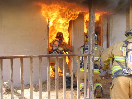
Figure 1.Flashover
flashover_figure1

Note: Photo by William Cobb, Cornelius – Lemley Fire Rescue

Flashover and Fire Development

There are a number of definitions or ways to describe flashover, but most importantly, it is a rapid transition to a fully developed fire.

A fuel package such as a couch or upholstered chair burning in open air progresses through four phases. In the incipient stage the fire involves only a small amount of fuel, as the fire moves into the growth stage, more fuel becomes involved and the speed of the combustion reaction increases. Eventually the entire object becomes involved and the fire is fully developed. As the fuel is consumed the fire begins to decay. Throughout this process, fire development is fuel controlled; the speed of fire development and energy released is dependent on the characteristics and configuration of the fuel. As combustion is taking place in the open, there is adequate oxygen to support combustion as the fire progresses through each of the four stages.

Heat of combustion is the energy released when a specific mass of fuel is completely burned. The total energy released when an object burns is dependent on the heat of combustion and the amount (mass) of fuel burned. Heat of combustion is measured in Joules (J). However, this only provides part of the picture. Heat release rate (HRR) is the amount energy released per unit of time. HRR is measured in Watts (W). A Watt is a Joule (unit of energy) per second (unit of time).  The fire service in the United States has traditionally used the British thermal unit (Btu) as a unit of energy. Using this unit of measure, HRR could be expressed in Btu/s. All of this is very interesting, but what does this have to do with flashover? As it turns out, heat release rate has everything to do with flashover!

When a fire is unconfined, much of the heat produced by the burning fuel escapes through radiation and convection. What changes when the fire occurs in a compartment? Fire development becomes influenced by the characteristics of the compartment. Other materials in the compartment as well as the walls, ceiling and floor absorb some of the energy released by the fire.  Some of the energy is not absorbed, but radiates back to the burning fuel continuing and accelerating the combustion process.

Hot smoke and air heated by the fire become more buoyant and rise, on contact with cooler materials such as the ceiling and walls of the compartment; heat is transferred to the cooler materials, raising their temperature. This heat transfer process raises the temperature of all materials in the compartment. As nearby fuel is heated, it begins to pyrolize. Eventually the rate of pyrolysis may reach a point where flaming combustion can be supported and the fire extends to other fuel packages.

However, the most significant difference with fire in a compartment is the compartment’s ventilation profile. The size, location, and configuration of openings in the compartment influence both the oxygen available for combustion and the retention or escape of thermal energy contained in the hot gases and smoke produced by the fire.

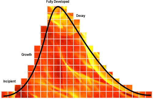
While the “stages of fire” have been described differently in fire service textbooks the phenomenon of fire development is the same. For our purposes, the stages of fire development in a compartment will be described as incipient, growth, fully developed and decay (see Figure 2). Despite dividing fire development into four “stages” the actual process is continuous with “stages” flowing from one to the next. While it may be possible to clearly define these transitions in the laboratory, in the field it is often difficult to tell when one ends and the next begins.

Figure 2. Stages of Fire Development
fire_development_stages

If the fire releases energy faster than it can escape from the compartment, temperature will increase and if sufficient energy is released, flashover will occur and the fire will transition rapidly from the growth to fully developed stage (see Figure 2). As this occurs, the fire will spread across all combustible surfaces in the compartment and flames will exit through compartment openings.

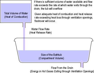
The bathtub analogy (see Figure 3) provides a simple way to explain the relationship between ventilation and flashover in a fuel controlled compartment fire.

Flashover has been analogously compared to the filling of a bathtub with the drain open. In this practical, though not perfect, analogy water represents the heat energy. The quantity of water available is the total heat of combustion of the available fuels (fuel load). The size of the spigot and the water pressure control the amount of water flow that is the heat release rate. The volume of the bathtub is analogous to the volume of the compartment and its ability to contain the heat energy. The size and location of the bathtub drain controlling the rate of water loss is the loss of heat energy through venting and conductance. In this analogy, if the bathtub becomes full and overflows, flashover occurs. (Kennedy & Kennedy, 2003, p. 7)

Figure 3. The Bathtub Analogy
bathtub_analogy

More to Follow

Posts over the next few weeks will continue to examine the process of reading the fire with further exploration of air track, heat, and flame indicators. In addition, I will be continuing this look at the flashover phenomena with a particular emphasis on the relationship between heat release rate, ventilation, and flashover.

Ed Hartin, MS, EFO, MIFireE, CFO

References

Close, K. (2005) Fire behavior vs. human behavior: Why the lessons from Cramer matter. Paper presented at the Eighth International Wildland Fir e Safety Summit, Missoula,MT. Retrieved May 13, 2008 from http://www.myfirecommunity.net/documents/Close.pdf

Drysdale, D. (1998). An introduction to fire dynamics. New York: John Wiley & Sons.

Gorbet, G & Hopkins, R. (2007) The current knowledge & training regarding backdraft, flashover, and other rapid fire progression phenomena. Paper presented at the annual meeting of the National Fire Protection Association, Boston, MA.

Kennedy, P. & Kennedy, K. (2003). Flashover and fire analysis: A discussion of the practical use of flashover in fire investigation. Retrieved July 30, 2009 from http://www.kennedy-fire.com/Flashover.pdf

Reading the Fire:
Air Track Indicators

Monday, July 27th, 2009

In Reading the Fire: How to Improve Your Skills, I discussed building a concept map fire of behavior indicators as a method to increase competence in reading the fire. Construction of a concept map increases awareness of key indicators and understanding their interrelationships. I am working through this process along with you, with the latest revision to my concept map. Thus far, I have examined Building Factors and Smoke Indicators; the first two categories in the B-SAHF (Building, Smoke, Air Track, Heat, and Flame) organizing scheme. For review of the discussion of building factors and smoke indicators see the following Reading the Fire posts:

Focus Question

Developing a concept map starts with a focus question that specifies the problem or issue that the map is intended to help resolve. Developing or refining a concept map identifying fire behavior indicators (FBI) and their interrelationships starts with the following focus question:

What building, smoke, air track, heat, and flame indicators
provide clues to current and potential fire behavior?

As you work through this process it is likely that you will uncover additional concepts that may be added to the Building Factors or Smoke Indicators concept maps. You may also identify interrelationships that you may not have thought of previously. Don’t forget to go back and capture these thoughts as you work on the air track map.

Air Track

In Reading the Fire: Smoke Indicators, I defined the difference between Smoke and Air Track indicators. However, it may be useful to revisit the difference between these two categories before engaging in a detailed look at Air Track indicators.

Smoke: What does the smoke look like and where is it coming from? This indicator can be extremely useful in determining the location and extent of the fire. Smoke indicators may be visible on the exterior as well as inside the building. Don’t forget that size-up and dynamic risk assessment must continue after you have made entry!

Air Track: Related to smoke, air track is the movement of both smoke (generally out from the fire area) and air (generally in towards the fire area). Observation of air track starts from the exterior but becomes more critical when making entry. What does the air track look like at the door? Air track continues to be significant when you are working on the interior.

While these two sets of indicators are interrelated, they are considered separately as air track relates to movement of both smoke and air.

Getting Started

When reading the fire it is important not to focus on a single indicator or category of indicators. However, Air Track indicators often provide critical information about stages of fire development, burning regime, differences in conditions throughout the building, and direction of fire spread.

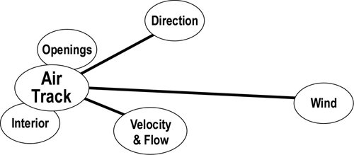
As always in developing a concept map it is important to move from general concepts to those that are more specific. Air Track must be considered at openings and inside the building. Basic indicators include direction, velocity & flow, and wind (as a major influence or modifying factor) as illustrated in Figure 1. However, you may choose to approach this somewhat differently.

Figure 1. Basic Air Track Indicators

air_track_indicators_5-2-2

Developing the Detail

Expanding the map requires identification of additional detail for each of the fundamental concepts. If an idea appears to be obviously related to one of the concepts already on the map, go ahead and add it. If you are unsure of where it might go, but it seems important, list it off to the side in a staging area for possible additions. Download a printer friendly version of Air Track Indicators to use as a starting point for this process.

Next Steps

Remember that the process of contracting your own map is likely as important as the (never quite) finished product. The following steps may help you expand and refine the Air Track indicators segment of the map:

  • Look at each of the subcategories individually and brainstorm additional detail. This works best if you collaborate with others.
  • Have a look at the following video clip using your partially completed map and notes as a guide to identifying important Air Track indicators. Think about what the Air Track indicators mean and visualize developing fire conditions inside the building.

The following video has some excellent Air Track indicators that may aid in developing and refining your Smoke Indicators concept map.

It may also be useful to go back and look at the video from Reading the Fire: Building Factors Part 2 or Reading the Fire: Smoke Indicators and focus in on Air Track Indicators.

Step Back and Look at the Entire Picture

Take this opportunity to engage with the rest of the B-SAHF indicators. Download and print the B-SAHF Worksheet. Consider the information provided in each of the short video clips and complete the worksheet for each. First, describe what you observe in terms of the Building, Smoke, Air Track, Heat, and Flame Indicators and then answer the following five standard questions?

  1. What additional information would you like to have? How could you obtain it?
  2. What stage(s) of development is the fire likely to be in (incipient, growth, fully developed, or decay)?
  3. What burning regime is the fire in (fuel controlled or ventilation controlled)?
  4. What conditions would you expect to find inside this building?
  5. How would you expect the fire to develop over the next two to three minutes?

Twitter

While I believe that Twitter has tremendous potential for quickly sharing information and building a community of practice, the plug-in that I have been using to integrate Twitter with the CFBT-US Blog has resulted in posts being cluttered with a tremendous amount of spam. I have disabled the plug-in, but will continue to provide updates on breaking news and information via Twitter. Follow edhartin on Twitter!

Ed Hartin, MS, EFO, MIFireE, CFO

Live Fire Simulations:
Key Elements of Fidelity Part 2

Thursday, July 23rd, 2009

Live Fire Simulations: Key Elements of Fidelity examined some of the important elements in physical fidelity, the extent to which the simulation looks and feels real. This post will begin the process of identifying key aspects of functional fidelity, the extent to which the simulation works and reacts realistically.

Maintaining the Balance

One important factor to consider in live fire training simulation is that despite the fact that it is a training exercise, the fire is real. While I too use the terms training fire and real fire, the combustion processes and fire dynamics in live fire training are the same as encountered in a structure fire. What is different is the type, amount, and geometry of the fuel used and the ventilation profile.

Providing complete functional fidelity (as well as physical fidelity) simply requires that structural environment, fuel loading, and ventilation be the same as would be encountered in an actual incident. However, this substantially increases variability of outcome and the risk to participants.

Use of a purpose built structure allows control of variability and provides the ability for repetitive and ongoing training. Purpose-built structures are often designed to use either solid Class A fuel or gaseous Class B fuel. Facility design and selection of fuel type should be based on a wide range of factors including provision of adequate fidelity for the type of training to be conducted, environmental issues, health and safety of participants, anticipated duty cycle (i.e., frequency and duration of training activity) and life-cycle cost (e.g., initial purchase price, ongoing maintenance costs).

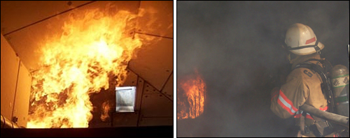
Figure 1. Live Fire Simulation with Gas (left) and Class A Fuel (right)

sim_comparison

As illustrated in Figure 1, there can be obvious and substantial differences in physical fidelity when gas fired props are used to simulate a typical compartment fire. Depending on the purpose of the simulation these physical differences can be important. However, differences in functional fidelity may be even more important.

Functional Fidelity

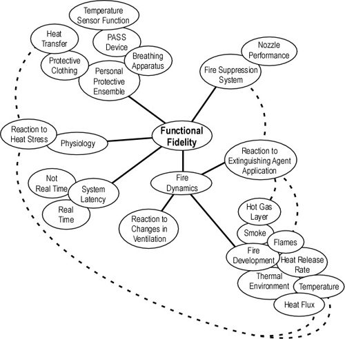
As stated earlier, functional fidelity is the extent to which the simulation works and reacts realistically. I have tentatively identified five subsystems related to functional fidelity of live fire simulation as illustrated in Figure 2.

Figure 2. Functional Fidelity Concept Map

functional_fidelity

This concept map is a simple and preliminary look at the elements of functional fidelity. Each of the concepts illustrated can be further refined and elaborated on to provide a clearer picture of physical fidelity in live fire training.

Physiology & Personal Protective Ensemble

Live fire simulation places the participant in a hostile environment requiring the use of personal protective clothing and self-contained breathing apparatus. Functional fidelity in these subsystems and their interaction with the thermal environment may or may not be a critical element of context, depending on the intended learning outcomes of the simulation. However, insulation of firefighters from the thermal environment encountered in structural firefighting delays, modifies, and my limit perception of critical thermal cues (e.g., high temperature, changes in temperature). Overcoming this challenge requires training in a realistic thermal context.

Fire Suppression System

One of the most critical elements in functional fidelity of the fire suppression system involves interaction with fire dynamics: Does the fire and fire environment (e.g., hot gas layer) react appropriately to extinguishing agent application? In some respects there may be a conflict between the desire for physical fidelity of the fire suppression system and functional fidelity of the interaction between extinguishing agent application and fire dynamics. For example, it may be desirable for participants to use the same flow rate (providing realistic nozzle reaction) in simulations as will be used in the structural firefighting environment. However, the limited fuel load typically used to provide a safe training environment do not result in the same required flow rate for fire control as fire in a typical residential or commercial compartment. Does use of a high flow handline in live fire simulation with limited fuel load create an unrealistic expectation of the performance under actual incident conditions? Which is more effective, realistic flow rate with a limited fuel load or matching of flow rate and fuel load to provide a realistic interaction between the fire and fire attack? This question remains to be answered.

The type of nozzle used presents a simpler issue related to functional fidelity in live fire simulation. Most combination nozzles have similar operational controls for controlling the flow of water (i.e. on and off) and pattern adjustment. However, there are subtle differences such as the extent of movement needed to adjust from straight stream to wide angle fog. Flow control mechanisms vary more widely from fixed flow rate, to variable flow and automatic nozzles. Firefighters must be able to select pattern and flow as necessary based on conditions encountered in the fire environment and intended method of water application. Use of a substantively different nozzle in training than during incident operations is likely to result in less than optimal performance. However, as with the question of flow rate, the extent to which this is a concern is unknown.

Fire Dynamics

Likely the greatest concerns with regards to functional fidelity are in the area of fire dynamics. If firefighters are to learn how fires develop and the impact of changes to ventilation profile and application of extinguishing agents, the fire must behave as it would under actual incident conditions (or as close to this ideal as can be safely and practically accomplished).

Most fuels encountered in structure fires are solids (e.g., furniture, interior finish, structural materials). Class A fuel used in live fire training, often has a lower heat of combustion and heat release rate than typical fuel in the built environment, but is similar in that it must undergo pyrolysis in order to burn; providing similar (but not identical) combustion performance. Combustion of Class A fuel also results in generation of significant smoke, another similarity to typical fuels in the built environment. Class B (gas) fuel used in structure fire simulations has a high heat of combustion with heat release rate controlled through engineering and design of the burner system. However, this fuel generally burns cleanly, necessitating introduction of artificial smoke to provide higher fidelity. Flaming combustion and smoke production must be mechanically controlled by a computerized system, a human operator, or both. The nature of the fuel and design of the combustion system also impact on the fires reaction to changes in ventilation and application of extinguishing agents such as water.

Changes to ventilation will not substantively influence fire behavior if the fire is fuel controlled. However, if the fire is ventilation controlled, changes in ventilation can have a significant impact on fire behavior (which may or may not be desirable, depending on the intended learning outcomes).

With Class A fuel, water applied to cool the hot gas layer or to fuel packages has a similar impact as it would in actual structural firefighting operations. The degree of similarity is dependent on the design of the compartment in which the training is being conducted as well as fuel factors and ventilation profile. With Class B fuel, temperature sensors, computerized controls, and a human operator all must interact to ensure that water application results in appropriate changes to combustion.

System Latency

In general, live fire training simulations are conducted in real time. However, time lag due to system limitations in Class B (gas) fired props or delay in instructor or operator perception of changing conditions in either Class A or B fueled props can influence system latency, resulting in faster or slower than normal interaction between  fire dynamics and fire control subsystems.

Closing Thoughts

While I admit I am (currently) biased in favor of live fire training simulation using Class A fuel, there is no reason why other systems such as those using Class B (gas) fuel could not be designed in such a way to provide higher fidelity. However, this would likely increase both complexity and cost. I have been also discussing the potential of computer based (non-live-fire) fire training systems to develop some (but likely not all) of the skills necessary to safely operate in the structural firefighting environment. This is something else to think about!

I will come back to this topic again from time to time as I gain additional insight into the elements of physical and functional fidelity in live fire training.

Remember the Past

Last Tuesday, was the second anniversary of the deaths of Captain Mathew Burton and Engineer Scott Desmond of the Contra Costa County Fire Protection District in California.

Figure 1. 149 Michele Drive-Alpha/Delta Corner

figure_1_fgi

Note: Contra Costa Fire Protection District (Firefighter Q76) Photo, Investigation Report: Michele Drive Line of Duty Deaths. This photo illustrates conditions shortly after 0159 (Q76 time of arrival).

July 21, 2007
Captain Matthew Charles Burton
Fire Engineer Scott Peter Desmond
Contra Costa County Fire Protection District, California

Captain Burton, Engineer Desmond, and another engineer were the crew of Engine 70. At 0143 hours, Engine 70 was dispatched to a residential fire alarm. As additional information was received, the incident was upgraded to a structural fire response with the addition of two engines, a quint, and a command officer.

Engine 70 arrived on the scene at 0150 hours and reported heavy fire and smoke from a small single-family residence. Firefighters reported that they had confirmed reports that two occupants of the home were still inside.

Captain Burton and Engineer Desmond advanced an attack line into the structure and flowed water on the fire. They reported that the fire had been knocked down and requested ventilation at 0155 hours. Captain Burton and Engineer Desmond exited the structure temporarily to retrieve a TIC, then re-entered the structure and went to the left toward the bedrooms with an attack line, while another crew went to the right without an attack line.

The engineer for Engine 70 placed a PPV fan at the front door. One of the civilian fire victims was located by the crew that had gone to the right; her removal was difficult and firefighters had to exit the building to ask for help. During this time, the fire inside the house advanced rapidly.

Firefighters had difficulty venting the roof due to multiple roofs, built-up roofing materials, and the type of construction.

A command officer arrived on the scene at approximately 0202 hours and began to look for Captain Burton to assume Command. The command officer tried to contact the Engine 70 crew by radio but was unsuccessful. A second alarm was requested, and a report of a missing firefighter was transmitted at approximately 0205 hours.

The fire had advanced within the structure and had to be controlled before firefighters could search for the missing crew. Captain Burton and Engineer Desmond were located and removed from the structure between 0212 and 0226 hours. The firefighters were found in a bedroom.

For additional information, see my earlier posts on this incident, the Contra Costa County Fire District Investigative Report, and National Institute for Occupational Safety and Health (NIOSH) Death in the Line of Duty Report.

Contra Costa County LODD: Part 1

Contra Costa County LODD: Part 2

Contra Costa County LODD: What Happened

Contra Costa County Fire Protection District Investigation Report: Michele Drive Line of Duty Deaths

National Institute for Occupational Safety and Health (NIOSH) Death in the Line of Duty Report F2007-28

Ed Hartin, MS, EFO, MIFireE, CFO

Reading the Fire:
Smoke Indicators Part 2

Monday, July 20th, 2009

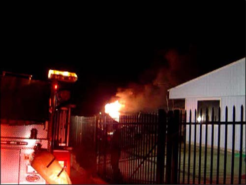
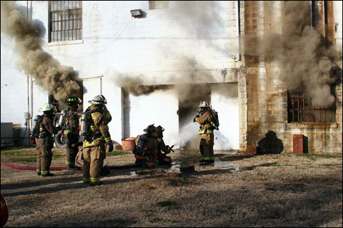
In many cases, smoke may provide the dominant indication that there is a fire in the building (but keep in mind that if you can see smoke on the exterior, there are also air track indicators). Have a look at Figure 1 and see what smoke indicators you observe.

Figure 1. Smoke Indicators

ranlo_c-fire_1

Note: Terry Moody Photo, Commercial Fire Ranlo, NC.

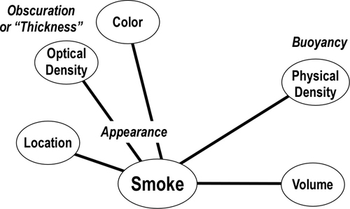
My prior post, Reading the Fire: Smoke Indicators began the process of developing or refining an existing concept map of smoke indicators. As a starting point, I have identified location, optical density (thickness), color, physical density (buoyancy), and volume as basic categories of smoke indicators (see Figure 2). However, you may choose to approach this somewhat differently.

Figure 2. Basic Categories of Smoke Indicators

smoke_indicators_5-2-2

These five categories provide a simple framework for examining smoke indicators, but considerably more detail may be developed within each category. Observation of smoke indicators can often provide an indication of the location and extent of the fire as well as its burning regime. However, it is essential that smoke indicators be integrated with other categories of indicators in the B-SAHF scheme to gain a clearer sense of fire conditions and likely fire behavior. Remember that looking at smoke alone may be misleading.

Location

The concept of smoke location applies to both the exterior and interior of the structure. From the exterior, consider the following:

  • Is smoke visible (this one is simple)?
  • What side(s) and level(s) of the building is the smoke visible from?
  • Is the smoke discharge from substantial openings such as open windows or doors?
  • Is smoke discharge limited to a single opening or is it visible from multiple openings?
  • Is the smoke discharge from points of normal building leakage (e.g., gaps around windows and doors, normal ventilation openings such as attic vents)?
  • Does the location of smoke discharge change over time?

These questions identify potential linkage to building factors indicators (i.e., actual openings) and air track (discharge of smoke and intake of air). Location may also be interrelated with other smoke indicators such as volume. For example, discharge of smoke from the top of a doorway has considerably different implications if the ceiling height is 7.3 m (24′) rather than 2.4 m (8′).

  • Smoke location continues to be important on the interior of the building.
  • Is smoke confined to a single compartment or group of compartments?
  • Is smoke present in void spaces?
  • Is smoke on one level or multiple levels?
  • Are there changes to the location of smoke over time?

Some indicators can be classified into more than one category. For example, smoke at the ceiling level could be considered from the perspective of location or (potentially more importantly) as an indicator of volume.

Volume

The language used to describe fire and smoke conditions in radio communications (e.g, size-up report or report on conditions) is often subjective and ambiguous. For example, what exactly is heavy smoke and how is that different from light smoke. I gained a new appreciation of the ambiguity of these terms when teaching fire officers who had English as a second or third language. Heavy and light commonly refer to weight, but in this case are frequently applied to volume or possibly optical density (or in other cases both of these characteristics). In an effort to provide clarity, I use the terms large and small in relation to volume. Note that this is still subjective, but I think a bit clearer than heavy and light.

From the exterior, consider the volume of smoke discharged. However, it is important to keep in mind that this may not be an indication of how much smoke is in the building. Volume becomes a bit more complex, but more important inside the building. The level of the neutral pressure plane at openings is related to both volume and air track. After entering a compartment, the level of the hot gas layer is a key indicator of smoke volume, but it must be considered in relation to building factor such as ceiling height. Firefighters often consider the height of the hot gas layer above the floor, but may not consider the depth of the hot gas layer down from the ceiling (which is equally important as an indicator of smoke volume). Compartments that are completely filled with smoke are said to be smoke logged. As with other indicators, it is essential to consider changes over time. In particular:

  • Is the volume of smoke discharged from the exterior increasing or decreasing?
  • Is the level of the neutral plane or hot gas layer raising or lowering?

Movement of the hot gas layer can indicate changes in volume or air track, both of which are important indicators of changing fire conditions, burning regime, and potential for extreme fire behavior such as ventilation induced flashover or backdraft.

Optical Density (Thickness)

As with the earlier discussion of heavy and light smoke, density can be a bit confusing as it is used in two different contexts. Most commonly, dense smoke is so thick that you can’t easily see through it. Optical density refers to obscuration, how difficult it is to see through the smoke. Thick or optically dense smoke contains a high concentration of particulates and is difficult to see through. High particulate concentration can also give the smoke the appearance of having texture (like velvet). Thickness is influenced by burning regime and the type of fuel that is burning. Ventilation controlled conditions and/or combustion of many synthetic fuels can result in development of optically dense or thick smoke.

  • How thick is the smoke on the exterior of the structure?
  • How thick is the smoke inside the building?
  • Does thickness differ based on location (a potential connection with location indicators here)?
  • Is thickness changing over time?

A key indicator substantively related to thickness is texture. Increased particulate concentration, increases obscuration, but if sufficiently high, also results in the appearance of texture. Smoke that looks like velvet is the result of extremely inefficient combustion and contains a high concentration of unburned fuel.

Color

Color has traditionally been an important but often misunderstood smoke indicator. Consider the following questions:

  • Which color smoke indicates the greatest hazard to firefighters: Creamy white or light tan, light gray, dark gray, brown, or black?
  • What color smoke indicates potential backdraft: White, yellow, brown, dark gray, or black?

The greatest challenge in making sense of smoke color is that it is the result of a number of interrelated factors including fuel type and burning regime. Light colored (e.g., white to light tan) smoke may contain a high concentration of unburned pyrolizate. While this smoke color is not typically associated with a high degree of hazard, this smoke is fuel and may present a significant threat. Yellowish smoke is typically associated with the backdraft phenomena. However, observation of a number of backdraft events points to considerably less certainty in the relationship between smoke color and backdraft.

Think about the range of smoke color that may be encountered in structural firefighting, but remember that all organic (carbon containing) fuel can produce black smoke under sufficiently ventilation controlled conditions.

Changes in color over time are a critical indicator of developing fire conditions and the effect of tactical operations.

In the early 1980s when my eldest daughter was five or six years old, she was observing live fire training in an acquired structure. During one evolution, she pointed out smoke conditions at a second floor window to a photographer who was taking pictures for a National Fire Protection Association (NFPA) training program. She stated “you see that light gray smoke coming from the window…it’s going to get black and then flames will come out”. Sure enough that was exactly what happened. The photographer was surprised. I was not. I pointed out that Heather had been to more fires than the photographer and that children pay attention to everything. There is a lesson here for us!

Physical Density (Buoyancy)

From a scientific perspective, density is mass per unit volume. Vapor density is the relative density of a gas or vapor in comparison to air (at standard temperature and pressure). The fire environment adds some complexity as increasing the temperature of a gas can cause it to expand, reducing its density (which is why hot smoke goes up). However, most of the constituents of smoke are heavier than air and will sink as they cool. Physical density refers to the buoyancy of the smoke.

Smoke that is buoyant will rise quickly and smoke that is not will hang low to the ground. Generally buoyancy is related to the temperature of the smoke, the higher the temperature, the less (physically) dense the smoke and the greater the buoyancy. Early in fire development smoke may not be that buoyant due to limited heat release. Development of a well defined hot gas layer indicates significant difference in temperature between the hot smoke and cooler air below. Later in the development of the fire, buoyancy may be affected by the operation of automatic sprinklers (or application of water from hoselines) or it may simply cool as it moves away from the fire. In evaluating the importance of physical density, consider the following questions:

  • What building factors might impact on buoyancy?
  • How does ambient temperature influence buoyancy?
  • What potential hazards does smoke with limited buoyancy (i.e., cool smoke) present?

Work in Progress

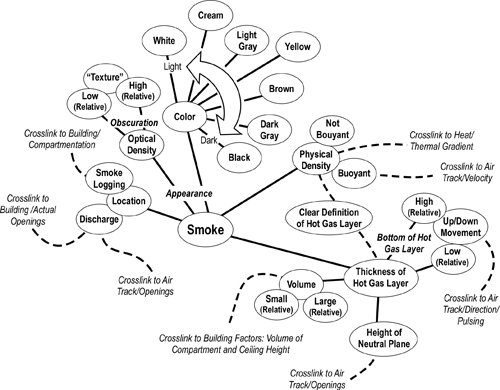
Hopefully we have been working on this project together and you have been developing or refining the smoke segment of your fire behavior indicators concept map. My current map is illustrated in Figure 3.

Figure 3. Smoke Indicators Concept Map v5.2.2.1

smoke_indicators_5-2-2-1

You can also download a printer friendly version of the Smoke Indicators Concept Map v5.2.2.1 (including notes made during development). As always, feedback is greatly appreciated.

Master Your Craft

Ed Hartin, MS, EFO, MIFireE, CFO

Live Fire Simulations:
Key Elements of Fidelity

Thursday, July 16th, 2009

Several earlier posts (Training Fires Versus Real Fires, Live Fire Training: Important Questions) introduced the concepts of live fire training as simulation, physical fidelity, and functional fidelity. This post will dig a bit deeper into what aspects of fidelity may be important in live fire training.

Interesting Puzzle

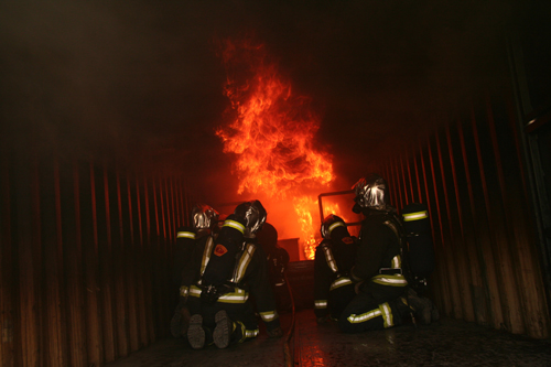
Physical fidelity is the extent to which the simulation looks and feels real. Functional fidelity is the extent to which the simulation works and reacts realistically. In Live Fire Training: Important Questions, I presented a puzzle provided by Roy Reyes of the Swedish Civil Contingencies Agency. He forwarded me the following photo (Figure 1) from a fire behavior instructor course that he had conducted in Valencia, Spain and posed two questions, one quite general and the other very specific:

  1. What do you see in the photo?
  2. Why are the flames in the hot gas layer in the center, and not across the entire width of the compartment?

Figure 1. Participants Conducting Fire Behavior Demonstration 2

demo_2_valencia

Physical and functional fidelity are potentially quite important in developing firefighters understanding of fire behavior and skill in application of fire control techniques. The two questions that Roy asks are important (and I will get back to them). However, two more fundamental questions could be asked: 1) To what extent is the fire behavior in this container based prop reflective of conditions that would be encountered in a “real” fire? 2) Does it matter (given the learning outcomes intended for this training session)?

Physical Fidelity

Physical fidelity is important in providing visual, audible, and tactile cues that are essential to developing and maintaining situational awareness. In addition, physical fidelity is a key component in firefighters’ perception of the realism of the simulation.

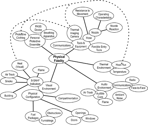
The concept of physical fidelity is simple. However, when you start to think about the live fire training environment, it quickly becomes more complex. The elements of fidelity related to flight simulation discussed in Live Fire Training: Important Questions as a starting point. Physical fidelity may include the firefighters’ personal protective ensemble, tools, and equipment as well as visual, audio, and thermal aspects of the environment. As illustrated in Figure 2, a number of these elements of physical fidelity are interrelated.

Figure 2. Physical Fidelity Concept Map

physical_fidelity_v1

This concept map is a simple and preliminary look at the elements of physical fidelity. Each of the concepts illustrated can be further refined and elaborated on to provide a clearer picture of physical fidelity in live fire training.

Functional Fidelity

While physical fidelity is important, functional fidelity; realistic functioning of the simulation, is likely even more important. Development of critical skills and the ability to read the impact of tactical action is dependent on adequate functional fidelity.

As with physical fidelity, the concept is straight forward, the simulation should function in a realistic manner. However, this is likely to be even more complex than simply looking realistic.

Roy’s puzzle provides an interesting starting point to think about the nature, function, and importance of functional fidelity.

The first question asked, what do you see in the photo? Firefighters are engaged in a training session in a container based CFBT cell with a fire located in the front on the right side. A well defined hot gas layer has developed with flames extending through the hot gas layer at the center of the compartment.

The second question is more significant. Why are the flames extending in the hot gas layer in the center of the compartment and not across the full width of the compartment? There could be a number of possible explanations, but it is likely that the metal walls of the container are acting as thermal ballast. Energy used to increase the temperature of the metal compartment walls (which have excellent thermal conductivity) is not being used in the combustion process (preventing flaming combustion next to the walls). The same phenomenon can be demonstrated by placing a coil of copper wire into a candle flame. This causes a reduction in flaming combustion, and in many cases the wire absorbs sufficient energy to extinguish the flame.

So, the thermal conductivity of the container walls can at times influence the behavior of flaming combustion in CFBT cells. Does this present a problem or is it simply an opportunity to present the puzzle to the learners and engage in a discussion about thermal ballast?

A subsequent post will examine this concept in greater depth and present a preliminary concept map illustrating key dimensions of functional fidelity.

Ed Hartin, MS, EFO, MIFireE, CFO

Reading the Fire 8

Monday, July 13th, 2009

As discussed in prior Reading the Fire posts and the ongoing series examining fire behavior indicators (FBI) using the B-SAHF (Building, Smoke, Air Track, Heat, and Flame) organizing scheme, developing proficiency requires practice. This post provides an opportunity to exercise your skills using three video segments shot during a commercial fire. In addition to practicing your skill in reading the fire, use these video clips to help develop or refine your smoke indicators concept map (see Reading the Fire: Smoke Indicators).

Commercial Fire

The Safety Harbor (FL) Fire Department responded to a commercial fire at Matrix Group Limited sporting goods warehouse and office building. First arriving crews initiated offensive operations but developing fire conditions required a shift to a defensive strategy. The 13,500 ft2 (1,254 m2) warehouse was destroyed resulting in an estimated 1.5 million dollars in damage. One firefighter experienced a back injury during firefighting operations.

Download and print two copies of the B-SAHF Worksheet. Watch the first 60 seconds of Video Segment 1. Consider the information provided in this segment of the video clip. First, describe what you observe in terms of the Building, Smoke, Air Track, Heat, and Flame Indicators and then answer the following five standard questions?

  1. What additional information would you like to have? How could you obtain it?
  2. What stage(s) of development is the fire likely to be in (incipient, growth, fully developed, or decay)?
  3. What burning regime is the fire in (fuel controlled or ventilation controlled)?
  4. What conditions would you expect to find inside this building?
  5. How would you expect the fire to develop over the next two to three minutes?

Video Segment 1

Give some thought to how building factors might be influencing fire behavior and the way in which other FBI might be presenting (see Reading the Fire: Building Factors Part 3), specifically:

What is the height of the building (and more importantly the interior compartments)? What is the likely impact on fire behavior and presentation of FBI?

  1. What is the building construction classification? Does this have an impact?
  2. This is a sporting goods warehouse and office occupancy. What type of contents (fuel ) would you anticipate (think about heat of combustion, heat release rate, mass of fuel, fuel geometry)?

Go back to Video Segment 1, examine conditions from 3:15 to 4:15, and consider the answers to the five standard questions on the B-SAHF worksheet.

  1. How have conditions changed?
  2. Would you change the answers to the five standard questions based on your current observations?

Watch the remainder of Video Segment 1 and continue your assessment of current conditions and fire behavior prediction.

  1. How do conditions change?
  2. What impact are tactical operations having on the fire? How does this influence the FBI?

Watch the first 1:30 of the Video Segment 2. Consider the information provided in this segment of the video clip. How have conditions changed from those observed at the start of Video Segment 1?

Using the second copy of the B-SAHF Worksheet, describe what you observe in terms of the Building, Smoke, Air Track, Heat, and Flame Indicators and then answer the following five standard questions?

  1. What additional information would you like to have? How could you obtain it?
  2. What stage(s) of development is the fire likely to be in (incipient, growth, fully developed, or decay)?
  3. What burning regime is the fire in (fuel controlled or ventilation controlled)?
  4. What conditions would you expect to find inside this building?
  5. How would you expect the fire to develop over the next two to three minutes?

Video Segment 2

Watch the remainder of Video Segment 2 and continue your assessment of current conditions and fire behavior prediction.

  1. How do conditions change?
  2. What impact are tactical operations having on the fire? How does this influence the FBI?

What smoke indicators did you identify during these two B-SAHF exercises? Were these identified on your Smoke Indicators Concept Map? If not, take a minute to update the map (or place them in the staging area for future consideration).

Watch the last video segment and see if there are any other smoke indicators that you might want to add to the map.

Video Segment 3

Master Your Craft

Ed Hartin, MS, EFO, MIFireE, CFO

Reading the Fire:
Smoke Indicators

Thursday, July 9th, 2009

In Reading the Fire: How to Improve Your Skills, I discussed building a concept map of fire behavior indicators as a method to increase competence in reading the fire. Construction of a concept map increases awareness of key indicators and understanding their interrelationships. I am working through this process along with you, with the latest revision to my concept map. Thus far, I have examined Building Factors, the first category of indicators in the B-SAHF (Building, Smoke, Air Track, Heat, and Flame) organizing scheme. For review of the discussion of building factors and revision of this segment of my concept map see the following three posts:

Reading the Fire: Building Factors

Reading the Fire: Building Factors Part 2

Reading the Fire: Building Factors Part 3

Focus Question

As pointed out at the start of this project, a concept map starts with a focus question that specifies the problem or issue that the map is intended to help resolve. The fire behavior indicators (FBI) concept map starts with the following focus question:

What building, smoke, air track, heat, and flame indicators
provide clues to current and potential fire behavior?

It is important to remember that a concept map is never finished. After you develop the first draft, it is always necessary to revise the map to increase clarity or add important concepts that you discover as work continues.

In the next few posts in the series, we will apply this focus question to smoke indicators.

Smoke Versus Air Track

There are a number of interrelationships between Smoke and Air Track. However, in the B-SAHF organizing scheme they are considered separately. As we begin to develop or refine the map of Smoke Indicators it is useful to revisit the difference between these two categories in the B-SAHF scheme as outlined in Reading the Fire: Building Factors

Smoke: What does the smoke look like and where is it coming from? This indicator can be extremely useful in determining the location and extent of the fire. Smoke indicators may be visible on the exterior as well as inside the building. Don’t forget that size-up and dynamic risk assessment must continue after you have made entry!

Air Track: Related to smoke, air track is the movement of both smoke (generally out from the fire area) and air (generally in towards the fire area). Observation of air track starts from the exterior but becomes more critical when making entry. What does the air track look like at the door? Air track continues to be significant when you are working on the interior.

Getting Started

When reading the fire it is important not to focus on a single indicator or category of indicators. However, Smoke Indicators often provide critical information about stages of fire development, burning regime, and differences in conditions throughout the building.

As always in developing a concept map it is important to move from general concepts to those that are more specific. Basic smoke indicators may include location, optical density (thickness), color, physical density (buoyancy), and volume as illustrated in Figure 1. However, you may choose to approach this somewhat differently.

Figure 1. Basic Smoke Indicators

smoke_indicators_5-2-2

Developing the Detail

Expanding the map requires identification of additional detail for each of the fundamental concepts. If an idea appears to be obviously related to one of the concepts already on the map, go ahead and add it. If you are unsure of where it might go, but it seems important, list it off to the side in a staging area for possible additions. Download a printer friendly version of Smoke Indicators to use as a starting point for this process.

Next Steps

Remember that the process of contracting your own map is likely as important as the (never quite) finished product. The following steps may help you expand and refine the Smoke Indicators segment of the map:

  • Look at each of the subcategories individually and brainstorm additional detail. This works best if you collaborate with others.
  • Have a look at the following video clip using your partially completed map and notes as a guide to identifying important smoke indicators. Think about what the smoke indicators mean and visualize developing fire conditions inside the building.

The following video has some excellent smoke indicators towards the middle of the clip that may aid in developing and refining your Smoke Indicators concept map.

Step Back and Look at the Entire Picture

I would not want to waste the opportunity to engage with the rest of the B-SAHF indicators. Download and print the B-SAHF Worksheet. Consider the information provided in each of the short video clips and complete the worksheet for each. First, describe what you observe in terms of the Building, Smoke, Air Track, Heat, and Flame Indicators and then answer the following five standard questions?

  1. What additional information would you like to have? How could you obtain it?
  2. What stage(s) of development is the fire likely to be in (incipient, growth, fully developed, or decay)?
  3. What burning regime is the fire in (fuel controlled or ventilation controlled)?
  4. What conditions would you expect to find inside this building?
  5. How would you expect the fire to develop over the next two to three minutes

Master Your Craft

Twitter

While I did not get any response from the questions I posted on Twitter related to Building Factors, I will continue this practice as we explore smoke indicators. Have a look [http://twitter.com/edhartin] and join in by responding to the questions. End your comments related to Fire Behavior Indicators on Twitter with #B-SAHF (this hashtag simplifies searching for FBI related posts). In addition to B-SAHF questions, I also post links to video clips and fire behavior related new items on Twitter.

Ed Hartin, MS, EFO, MIFireE, CFO

Live Fire Training:
Important Questions

Monday, July 6th, 2009

In several recent posts (Training Fires and “Real” Fires and Live Fire Training in Purpose Built Structures, I emphasized that all live fire training is a simulation. Fidelity is the extent to which the simulation replicates reality.

Figure 1. Training in an Acquired Structure

salquist_acquired_structure

Note: Ed Hartin Photo

The Questions

Some firefighters and fire officers subscribe to the belief that use of acquired structures with realistic fuel loading is the only way to develop the necessary competence and skills to operate safely and effectively on the fireground. However, current standards such as National Fire Protection Association (NFPA) 1403 Standard on Live Fire Training (2007) places specific constraints on fuel types and loading. Some departments are faced with environmental constraints that preclude burning Class A fuel for structural live fire training and consequently use gas fired structures (or don’t conduct live fire training at all). Most departments who have access to purpose built structures and props for structural live fire training are limited to a single type of facility (due to economic constraints). This gives rise to an interesting set of questions:

  • What degree of simulation fidelity is necessary to develop the knowledge and skills necessary for safe and effective operation on the fireground?
  • What are the key elements of fidelity for various learning outcomes such as 1) developing understanding of fire development in a compartment, 2) dynamic risk assessment, inclusive of recognizing critical fire behavior indicators, 3) selecting appropriate fire control techniques, 4) developing competence and confidence when operating in a hazardous environment, 5) developing skill in nozzle operation and technique, 6) evaluating the effect of tactical operations.
  • Is live fire training the only or most effective simulation method for achieving these learning outcomes? If so, what type of simulation will safely provide the required degree of fidelity? If not, what other simulation method may be used in place of, or in addition to live fire training to provide the required degree of fidelity?

I believe that effective performance under stressful conditions requires substantial training in a realistic context. However, the answers to the preceding questions have not yet been determined. What we have is a great deal of strongly held opinion without supporting discipline or task specific evidence.

Dimensions of Fidelity

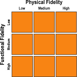
As discussed in Training Fires and “Real” Fires, fidelity can be examined in a number of different ways, but one simple approach is to consider physical and functional characteristics of the simulation. Physical fidelity is the extent to which the simulation looks and feels real. Functional fidelity is the extent to which the simulation works and reacts realistically.

Figure 2. Two-Dimensional Fidelity Matrix

sim_model_v1

However, this simple model provides limited guidance when examining questions related to live fire training. Here it is necessary to consider: What are the key elements of physical and functional fidelity necessary to support the specific learning outcomes intended from a given training evolution?

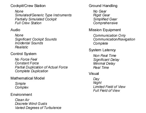
In A Handbook of Flight Simulation Fidelity Requirements for Human Factors Research, Rehman (1995) describes three purposes of aircraft flight simulation: 1) provide practice on specific skills, 2) reinforce acquisition and use of job-relevant knowledge, or 3) to evaluate a system or new concept. The fidelity requirements for each of these three purposes may be quite different. In addition, fidelity applies to the simulator itself, the participants, and related or events external to the simulator. In a flight simulator, each subsystem of the simulator (e.g., cockpit layout, audio, motion) has specific fidelity characteristics that must be considered as illustrated in Figure 3.

Figure 3. Flight Simulator Subsystem Fidelity Characteristics

sim_fidelity_dimensions1

Note: Adapted from A Handbook of Flight Simulation Fidelity Requirements for Human Factors Research.

How might these concepts be applied to evaluating fidelity requirements for live fire training? Determining the answers to the questions posed in this post will require a significant research effort (and related funding). However, the first step in this process is to clarify, refine, and tightly focus the questions that this research needs to answer.

My next post will examine this interesting topic a bit further.

An Interesting Puzzle

Closely related to the topic of simulation fidelity, I was provided with an interesting puzzle by my friend Roy Reyes of the Swedish Civil Contingencies Agency. He forwarded me the following photo (Figure 4) from a fire behavior instructor course that he had conducted in Valencia, Spain. His first question was what do you see in the photo?

Figure 4. Participants Conducting Fire Behavior Demonstration 2

demo_2_valencia

Note: Roy Reyes Photo

The second question is a bit more specific, why are the flames in the hot gas layer in the center, and not across the entire width of the compartment?

The answer to this question provides an important learning opportunity related to how simulator and simulation design impact on fidelity and the importance of the instructor in establishing context.

I will come back to these questions in my next post!

Ed Hartin, MS, EFO, MIFIreE, CFO

References

National Fire Protection Association (NFPA). (2007) NFPA 1403 Standard on Live Fire Training Evolutions. Quincy, MA: Author.

Rehman, A. (1995). A handbook of flight simulation fidelity requirements for human factors research, Report Number DOT/FAA/CT-TN95/46. Retrieved July 6, 2009 from http://ntl.bts.gov/lib/000/800/858/tn95_46.pdf

Reading the Fire:
Building Factors Part 3

Thursday, July 2nd, 2009

While I have not had much input (via Twitter or post comments), I have been working on the Building Factors map to include factors related to the surrounding environment and to revise fire protection systems, construction, fuel, size, and ventilation profile.

Surrounding Environment

Previous versions of the fire behavior indicators (FBI) concept map considered wind effects as a component of air track (which it influences significantly), but did not consider other environmental influences on fire behavior. After considerable thought, I recognized that building factors (and to some extent all of the FBI) can be viewed like Matryoshka Dolls (nested Russian dolls) when used to think about a single compartment, the building, or the building in its surrounding environment.

Environmental factors include exposures (which fire can extend from or to), ambient weather conditions, and terrain. Weather and terrain likely deserve a bit of explanation. While these factors are recognized as major players in wildland fire behavior, their influence is often not as quickly recognized in the built environment. Wind is likely the greatest meteorological concern when dealing with compartment fires. As discussed in prior posts (Wind Driven Fires, NIST Wind Driven Fire Experiments: Establishing a Baseline, Evaluating Firefighting Tactics Under Wind Driven Conditions), wind driven fires present a significant threat to firefighters. However, while buildings are generally designed to minimize the impact of temperature, humidity, and precipitation on their occupants, these factors can influence fire behavior directly or indirectly. For example, combustible exterior surfaces (e.g., wood shingle or shake roofs) present an increased hazard if humidity is low and ambient temperature is high. The influence of terrain may not be quite as obvious. In some cases, terrain may influence wind effects and in others slope may result in differences in elevation on each side of the building. When unrecognized, this has been a factor in a number of firefighter fatalities due to the resulting air track and path of fire spread from lower, to upper floors. For example see NIOSH (1999) Death in the Line of Duty Report F99-21 and Simulation of the Dynamics of the Fire at 3146 Cherry Road NE, Washington D.C. (NIST, 2000).

Fire Protection Systems

Fire suppression systems such as automatic sprinklers can obviously have a direct influence on fire development in a protected compartment. Similarly, fire detection may reduce the time between ignition and intervention by the fire department. However, prior versions of the FBI concept map did not include passive fire protection such as fire rated separations (other than generically as compartmentation).

Construction & Fuel

Prior versions of the FBI map linked Building to Contents and Construction. I have changed this to consider both contents and construction as fuel, while maintaining a link between building factors and construction as there are other facets of construction that can influence fire behavior. However, this area of the map remains a bit tentative (with more work to be done). Other changes to this part of the map include the addition of fire load density (kJ/m2) and increasing clarity of the concepts related to flow rate requirements for fire control.

Size

The concept of size can be a bit confusing as it applies to individual compartments (habitable or void spaces), interconnected compartments, and the entire building. Refinements include the addition of void spaces and normal door position to the concept of compartmentation.

Ventilation Profile

Thermal performance of potential openings has been added to ventilation profile, recognizing that single pane windows perform considerably different than multi-pane, energy efficient windows under fire conditions. In addition, a note was added to clarify that ventilation may be from compartment to compartment or from the building to the external environment.

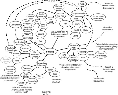
Figure 1. Building Factors Concept Map v5.2.2.1

building_factors_5-2-2-1

You can also download a larger, printer friendly version of the Building Factors Concept Map v5.2.2.1 (including notes made during development). Several colleagues who have had a look at this map observed that it is extremely complicated. While this is true, if you take the time to examine each of the factors and give some thought to the interrelated influences on fire behavior, it becomes a bit clearer. Remember that this is my representation of the concepts, yours will likely be a bit different! As always, feedback is greatly appreciated.

Master Your Craft

Subsequent posts will examine the rest of the B-SAHF (Building, Smoke, Air Track, Heat, & Flame) organizing scheme for fire behavior indicators.

Ed Hartin, MS, EFO, MIFireE, CFO

References

National Institute for Occupational Safety and Health (NIOSH) (1999) Death in the line of duty report F99-21. Retrieved July 2, 2009 from http://www.cdc.gov/niosh/fire/pdfs/face9921.pdf

National Insitute for Standards and Technology (NIST). Simulation of the Dynamics of the Fire at 3146 Cherry Road NE, Washington D.C. Retrieved July 2, 2009 from http://www.fire.nist.gov/CDPUBS/NISTIR_6510/6510c.pdf