Archive for December, 2009

Effective and Efficient Fire Streams: Part 3

Thursday, December 31st, 2009

The first two posts in this series, Effective and Efficient Fire Streams, and Effective and Efficient Fire Streams: Part 2, discussed theoretical cooling capacity, fire stream efficiency, flow rate, nozzle design characteristics and methods of use. This post drills down with a look at the relationships between the pump, hose, and nozzle in developing effective and efficient fire streams.

Where to Start?

It is likely that the most common system for developing effective and efficient fire streams involves use of combination nozzles having a designed operating pressure of approximately 100 psi (690 kPa) and what my British and Australian colleagues would refer to as “layflat” hose with a diameter between 1-1/2” (38 mm) and 2” (52 mm). As this type of system seems to be common to most fire services (with a few variations), this is a good place to start.

Hydraulics

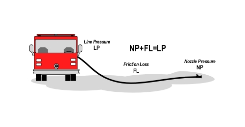
Developing effective and efficient fire streams requires an understanding of basic principles of fireground hydraulics. As discussed in earlier posts, each nozzle has a designed operating pressure. In order to provide this pressure at the nozzle, it is necessary to overcome loss of pressure in hoselines due to friction loss and increases in elevation.. Add To keep this discussion simple, the pump and nozzle will be at the same elevation.

Figure 1. Basic Handline Hydraulics
handline_line_pressure

The major factors influencing friction loss in a hoseline are flow rate and diameter of the hoseline. The Pumping Apparatus Driver/Operator Handbook (IFSTA, 2006) identifies four friction loss principles:

First Principle: All other conditions being equal, friction loss varies directly with the length of the hoseline.

Second Principle: When hoseline diameter remains constant, friction loss varies approximately with the square of the increase in flow rate. Doubling the flow increases friction loss by a factor four.

Third Principle: At the same flow rate, friction loss varies inversely as the fifth power of the diameter of the hoseline (increasing hose diameter, even a small amount has a dramatic effect on friction loss. Increasing hose diameter from 1-1/2” (38 mm) to 1-3/4” (45 mm) reduces friction loss by 46% (1.505/1.755=0.46).

Fourth Principle: If hose diameter and flow rate are held constant, friction loss is independent of pressure.

Apparatus operators must understand these basic concepts and be proficient at determining the line pressure required to develop adequate nozzle pressure to produce the necessary reach and droplet size for effective and efficient fire control operations.

Scalability

Critical and optimal flow rate are dependent on the heat release rate from the fire. The higher the heat release rate, the higher the flow rate necessary to achieve fire control. However, the flow rate required for gas cooling (unignited gas phase fuel) is not so dependent on HRR! Cooling unignited gases is most effective at a considerably lower flow rate. 30 gal/min (115 l/min) to 60 gal/min (230 l/min) is often sufficient for gas cooling (unless compartment size is extremely large).

Single flow nozzles are simple to operate as control is limited to the angle of the fog pattern and the shutoff valve. The term single flow is a bit misleading in that flow can be varied using the shutoff valve. Partially opening the shutoff valve will provide a reduced flow rate. However, partially opening the valve also provides considerably lower nozzle pressure (at the orifice), resulting in poor stream performance (limited reach and large droplet size). If a nozzle is designed to develop the low flow rate and small droplet size that is typically optimal for gas cooling, it may not have sufficient flow for direct attack on larger fires or fires in larger compartments. On the other hand, nozzle designed for higher flow rates may be ideal for direct attack on larger fires or large compartments, but are inefficient and in some cases ineffective when used for gas cooling.

Ideally, the hose and nozzle system should be scalable to provide effective and efficient operation over a fairly wide range of flow rates. At the low end, the nozzle should be capable of gas cooling at 30 gpm (115 lpm). The upper end of flow capability for direct attack has room for considerable debate.

Some agencies such as the New South Wales Fire Brigades in Australia uses the Akron Turbojet with flow settings of 30, 60, 95, & 125 gal/min (115, 230, 360, 475 l/min). On the other hand, many fire departments in the United States use nozzles having upper end flow rates of 150-200 gal/min (568-757 l/min). Having a higher flow capability provides the ability to deal with higher HRR and larger size compartments typical in contemporary residential structures and commercial buildings.

Variable flow and automatic nozzles provide the capability to vary flow rate as needed to deal with varied tactical applications and fire conditions. However, each accomplishes this task in a different manner.

Variable Flow Nozzles

When using a variable flow nozzle, the size of the nozzle orifice can be changed manually to provide several specific flow rates at the designed nozzle pressure. This requires that the apparatus operator know the flow setting of the nozzle as well as the length of line in order to determine the line pressure required to develop the correct nozzle pressure. At first glance, it appears that changing flow rates on the fly would require a great deal of radio communication between the nozzle team and apparatus operator (communication of flow setting each time it is changed). However, this challenge can easily be overcome!

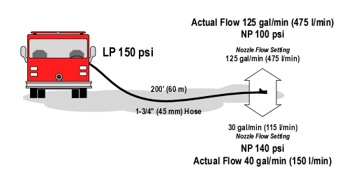
Consider what happens when the nozzle operator changes flow setting and the apparatus operator maintains the same line pressure. If the flow setting is reduced (decreasing the orifice size), flow rate will be decreased, reducing friction loss in the hoseline. As the line pressure remains the same, the pressure that is not used to overcome friction loss increases nozzle pressure. For example, if a 200’ (60 m) long 1-3/4” (45 mm) hoseline equipped with a variable flow nozzle such as an Akron Turbojet is flowing 125 gal/min (475 l/min) at a nozzle pressure of 100 psi (690 kPa) and the nozzle operator changes the flow setting to 30 gal/min (115 l/min) and discharge pressure remains constant, the flow rate will be reduced to 40 gal/min (150 l/min) at a nozzle pressure of 140 psi (965 kPa) (see Figure 2).

Figure 2. Changes in Flow Rate and Nozzle Pressure
variable_flow_example

Note: The preceding example is based on tests conducted with an Akron Turbojet variable flow nozzle.

How does the reduced flow rate and increased nozzle pressure impact on fire stream effectiveness and efficiency? Increased velocity of discharge (resulting from the higher nozzle pressure) results in reduced droplet size, increasing the effectiveness and efficiency of the stream when used for gas cooling. The reduced flow rate may be insufficient for direct attack on larger fires, but the nozzle operator can quickly return to a higher flow rate by adjusting the nozzle flow control. Pumping to deliver maximum flow allows the nozzle operator to select the flow rate and nozzle pressure that is appropriate based on conditions.

Automatic Nozzles

Automatic nozzles maintain a relatively constant nozzle pressure through a given flow range. The nozzle operator controls flow using the shutoff (opening the nozzle partially provides a lower flow rate than when the nozzle is opened fully).

The shutoff valve controls both water application and flow rate, automatic nozzles are a bit simpler to use, but unlike the example provided on how to maximize the capability with the variable flow nozzle, nozzle pressure remains constant (e.g., 100 psi (690 kPa).

System Design

The starting point for designing an effective system to develop effective and efficient fire streams needs to consider the desired flow rate, typical length of hoselines required, and tactical applications. Remember there is no universal, one size fits all, answer to this question. Fire services around the world successfully use a variety of different systems. Consider the following as a starting point:

  • Both variable flow and automatic nozzles can be used effectively to apply water at varied flow rates. Automatic nozzles are simpler to operate (as they have fewer controls), but at lower flow rates are likely to develop larger droplets than variable flow nozzles operated at over 100 psi (690 kPa).
  • Hoseline diameter should be sufficient to develop the desired flow rate given the likely attack line length. Remember that as hoseline diameter increases, friction loss decreases (but so may mobility).
  • Pumping for maximum flow from the nozzle provides the nozzle operator with maximum flexibility as flow rate can be selected based on conditions. If other than maximum flow is selected as the standard flow rate it is important to train nozzle operators to request that the apparatus operator increase discharge pressure to provide maximum flow if needed.

The next post in this series will examine applications of high pressure and ultra-high pressure systems for developing effective and efficient fire streams. While considerably different than the system described in this post, this technology shows promise in expanding the range of tools available for fire control operations.

Ed Hartin, MS, EFO, MIFireE, CFO

References

International Fire Service Training Association (IFSTA). (2006). Pumping apparatus driver/operator handbook (2nd ed). Stillwater, OK: Fire Protection Publications.

Did You Ever Wonder?

Thursday, December 24th, 2009

The ability to read the fire and predict likely fire behavior is a critical skill for both firefighters and fire officers. Previous posts have examined how to use the B-SAHF scheme to recognize critical fire behavior indicators and identify the stage of fire development, burning regime, and potential for extreme fire behavior such as flashover or backdraft. However, there is something missing!

Experience is critical to adapting standard procedures and practices to a complex and dynamic operational environment. However, learning about fire behavior and changes in fire conditions based on fireground observations are a bit like a black box test. Black box testing is a technique for testing computer software in which the internal workings of the item being tested are not known by the tester. This is not entirely true in the case of fire behavior, but there is much that we don’t know when assessing conditions on the fireground. How long has the fire been burning? What are the specific characteristics of the fuel? What sort of internal compartmentation is present? What exactly is the ventilation profile? Some of these factors can be determined during fire investigation and it is also possible to determine (with some degree of uncertainty) what influence these factors had on the outcome of the incident. Did you ever wonder how fire behavior would have changed if you had used different tactics? Unfortunately, in real life there are no “do overs”!

UL Tactical Ventilation Research Project

One of the people who has asked himself the question of what would have changed if different tactics were used is Underwriters Laboratories Fire Protection Engineer Steve Kerber.

Underwriters Laboratories (UL) has received a Firefighter Safety Research and Development Grant from the Department of Homeland Security (DHS). This research project will investigate and analyze the impact of natural horizontal ventilation on fire development and conditions in legacy (older, more highly compartmented) and contemporary (multi-level, open floor plan) residential structures.

Preliminary work has included review of literature related to horizontal ventilation and incidents in which ventilation had a significant influence on firefighter injuries and fatalities. In addition, UL has done preliminary work on the performance of various structural components such as single and multi-pane windows as preliminary input for design of full scale residential fire experiments.

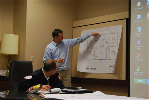
In mid-December 2009, Steve Kerber met with the project advisory panel comprised of Captain Charles Bailey, Montgomery County (MD) Fire Department; Lieutenant John Ceriello New York City Fire Department, Firefighter James Dalton and Director of Training Richard Edgeworth, Chicago Fire Department, Chief Ed Hartin, Central Whidbey Island (WA) Fire & Rescue, Chief Otto Huber Loveland-Symmes (OH) Fire Department, and Chief Mark Nolan, Northbrook (IL) Fire Department. In addition, the advisory panel includes Fire Protection Engineers Dan Madrzykowski from the National Institute of Standards and Technology (NIST) and Dr. Stefan Svensson, a research and development engineer from the Swedish Civil Contingencies Agency.

Figure 1. Defining Experiment Parameters for the Contemporary Structure

kerber_plans

The main task presented to the advisory panel at the first meeting was to aid in defining the parameters for the experiment; including fire location, changes in ventilation profile, timing of these changes, and instrumentation to measure effects on fire development and conditions.

UL Large Fire Research Facility

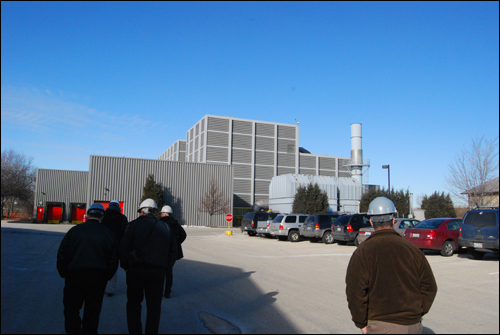
The ventilation experiments will be conducted at the UL Large Fire Research Facility in Northbrook, IL. From the exterior, this facility simply looks like a large industrial building (see Figure 2). However, the interior of the structure includes a unique facility for fire research.

Figure 2. UL Large Fire Research Facility

ul_large_fire_lab_outside

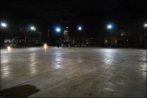
One of the facilities inside this building is a 100’ x 120’ (30.48 m x 36.58 m) with a ceiling height that is adjustable up to 50’ (15.24 m) (see Figure 3). All of the smoke resulting from tests in this facility is exhausted through a system designed to oxidize unburned fuel and scrub hazardous products from the effluent prior to discharge to the atmosphere. Tests are monitored from a control room that overlooks the large burn room.

Figure 3. Large Burn Room

ul_large_fire_lab_inside

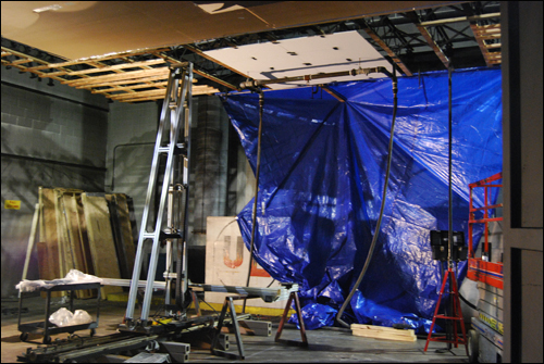
Over the next month, the two residential structures to be used for the ventilation experiments will be constructed inside the large burn room at the UL Large Fire Test Facility. After construction is complete, a series of 16 full scale fire experiments is planned to evaluate a range of different horizontal ventilation scenarios.

Research with the Fire Service

Steve Kerber has often stated that it is essential that scientists and engineers conduct research with, not for, the fire service. Engagement between researchers and firefighters on the street is essential in advancement of our profession. With this ventilation research project, Underwriters Laboratories is actively engaged in this process.

The outcome of this project will not simply be an academic paper (but there might be one or more of those as well). As part of the DHS grant, UL will be developing an on-line course to present the results of the experiments and their practical application on the fireground.

Happy Holidays,

Ed Hartin, MS, EFO, MIFireE, CFO

Effective and Efficient Fire Streams: Part 2

Friday, December 18th, 2009

The first post in this series, Effective and Efficient Fire Streams, discussed theoretical cooling capacity, fire stream efficiency, and flow rate. This post extends the discussion, by examining how nozzle design characteristics and methods of use influence efficiency.

Think!

I do not ask that anyone believe anything that I say (or write in this blog) simply because I said so. Firefighters� opinions about nozzles are as strong as their opinions about what color fire apparatus should be painted and what type of helmet should be used to protect our heads. Each kind and type of nozzle discussed in this post is being used by firefighters all over the world to extinguish fires in buildings. This does not mean that they are all equally effective, or appropriate in all circumstances. I challenge you to think about the physics of fire control and examine your assumptions about nozzles, fire stream characteristics, and how to develop effective and efficient fire streams.

Nozzle Classification

There are several different ways to approach classification of nozzles used in structural firefighting. One simple approach is to consider the pattern or patterns in which water can be applied:

Solid Stream/Smooth Bore: This type of nozzle provides a single pattern consisting of a jet of water that maintains coherence throughout its effective reach (breaking up into extremely large droplets beyond that point)

Combination: This type of nozzle can produce a variety of patterns from a straight stream to a fog cone. Both the straight stream and fog cone are comprised of small droplets of varying diameters. Droplet diameter and consistency of droplet size is dependent on nozzle design and operating pressure (higher pressure results in smaller droplets).

Special Purpose Nozzles: In addition to solid stream and combination nozzles, there are a variety of other specialized nozzles such as piercing nozzles (fog nails), cellar nozzles (of various types), and ultra high pressure solid stream nozzles that can be used for cutting through a variety of materials as well as to produce a fog pattern with extremely small droplets. Specialized nozzles and in particular high pressure and ultra-high pressure systems will be examined in detail in a subsequent post in this series.

Nozzle Characteristics

Beyond simple classification of structural firefighting nozzles as solid stream, combination, or special purpose, nozzles may be further classified based on a number of other characteristics such as the flow rate(s) or flow range and designed operating pressure.

Single Flow: Some nozzles are designed to provide a specific, fixed flow rate at their designed operating pressure. This includes solid stream nozzles with a single sized tip and fixed flow rate combination nozzles. While these nozzles are considered to provide a single flow rate, this is not exactly true. The nozzle orifice is of fixed size, providing a given flow rate at a specified nozzle pressure. As discussed in Under Pressure, flow rate from an opening is based on the area of the opening and the velocity of the water being discharged. Increased or decreased nozzle pressure influences flow rate. For example, increasing the nozzle pressure on a solid stream nozzle from 50 psi (345 kPa) to 80 psi (352 kPa) increases flow rate by approximately 22%.

Variable Flow: Nozzles may also be designed to allow orifice size to be changed, providing variable flow rates at a given nozzle pressure. With solid stream nozzles, this is accomplished by changing the tip size. With some combination nozzles, flow and pattern vary together (e.g., the fog pattern has a lower flow rate than the straight stream setting). However, most modern combination nozzles used for structural firefighting allow adjustment of the spray pattern while maintaining flow rate. Variable flow combination nozzles may be manually adjustable with several different flow rate settings at a specified nozzle pressure.

Automatic Nozzles: Another type of nozzle that allows variation of flow rate is the automatic nozzle. With this design the nozzle adjusts flow rate by varying orifice size automatically to maintain a relatively constant nozzle pressure. With automatic nozzles the flow range specifies the lowest and highest flow rate at the designed nozzle pressure. Some automatic nozzles allow adjustment of the nozzle pressure setting to allow operation at two different nozzle pressures such as 100 psi (690 kPa) and 50 psi (345 kPa).

Nozzle Pressure: At one time the question of nozzle pressure was fairly simple, combination nozzles generally were designed to operate at 100 psi (690 kPa) nozzle pressure. However, today it is not that simple. For a variety of reasons ranging from limited pressure available from high-rise standpipe systems to the desire for lower nozzle reaction force, nozzle manufacturers are producing combination nozzles with varied designed operating pressures (commonly 50 psi (345 kPa), 75 psi (517 kPa), and 100 psi (690 kPa).

Nozzle Performance

Floyd Nelson (1989) captured the essence of nozzle performance in the following statement: �In principle, firefighting is very simple. All one needs to do is put the right amount of water in the right place and the fire is controlled� (p. 102).

Nozzles used for gas cooling must produce small droplets, be capable of varying the angle of the fog cone to have sufficient reach to cover varied sizes of compartments. Droplets with a diameter of 0.3 mm are small enough to vaporize readily in the hot gas layer, but also have sufficient mass to travel a reasonable distance (Herterich, 1960). Droplets larger than 1 mm are likely to penetrate some distance through hot gases and flames without completely vaporizing (S�rdqvist, 2001). In reality, while we know a fair bit about droplet size and performance. We don�t know much at all about the droplet sizes produced by the nozzles we are using.

What we do know is that lower pressure nozzles develop larger droplets than higher pressure nozzles of the same general design. Specific design characteristics such as the angle that the water must take as it exits the orifice and forms the fog cone also impact on droplet size. This can be illustrated using a nozzle such as the Akron Turbojet. When set on 30 gal/min (115 l/m) or 60 gal/min and operated at a nozzle pressure of 100 psi, droplet size is extremely small, providing excellent gas cooling performance. However, when flow rate is increased to 95 gal/min (360 l/min) or 125 gal/min (473 l/min) droplet size increases dramatically. While still effective for gas cooling, water application at these flow rates is less efficient.

There is no standardized test used for nozzles that determines the range of droplet sizes produced under different flow rates, nozzle pressures, cone angles, etc. However, there is light at the end of the tunnel. The technology exists to answer this interesting (and I believe important) question. Figures 1 and 2 illustrate a system comprised of lasers and a high speed camera that is used to determine droplet size from sprinkler heads. This system could also be used to assess droplet size developed by handline nozzles (if funding was available).

Figure 1. UL Sprinkler Droplet Size Test Facility

droplet_size_lab

Note: Underwriters Laboratories, Northbrook, IL

Figure 2. Laser and Camera Used for Measuring Droplet Size

droplet_laser_camera

Note: Underwriters Laboratories, Northbrook, IL

One factor that complicates things when considering droplet size and nozzle performance is that the nozzle is only one part of the equation. The nozzle operator has a significant influence on performance. For example, in a short pulse, if the nozzle is opened quickly, more of the droplets are formed with the nozzle operating at full nozzle pressure than if it is opened slowly (providing a lower pressure at the start of the pulse). The same is true if the nozzle is closed slowly rather than quickly. This is less significant with long pulses as the opening and closing phase of the pulse comprises a small percentage of the total operating time.

In direct and indirect attack, water must pass through the hot gas layer and reach burning fuel (direct attack) and/or hot surfaces (indirect attack) before significantly evaporating. If distances are not great or the temperature of the hot gas layer is not extremely high, a straight stream or narrow fog cone comprised of small droplets may be effective in accomplishing this task. When gas cooling precedes direct attack, this is often the case. However, if the distance between the nozzle and intended target is large and/or the temperature of the hot gases is high, larger droplets (or a solid stream) may be much more effective.

Selection

Many factors can (and should) be considered when selecting a system to develop effective and efficient fire streams. I used the word system intentionally as a nozzle is useless without hose, a pump, source of water, and most importantly knowledgeable and skilled firefighters to operate it.

The ideal system to develop effective and efficient fire streams for offensive firefighting would have the following capabilities (but not necessarily at the same time).

  • Can produce small droplets for gas cooling
  • Can produce larger droplets to penetrate hot gases and reach burning fuel or hot surfaces
  • Adjustable fog cone angle (allows effective reach in varied size compartments)
  • Adequate reach and stream cohesion when adjusted to straight stream
  • Ability to vary flow rate depending on fire conditions and tactical application
  • Light weight and high level of maneuverability
  • Ease of operation to simplify training requirements

At present, it is unlikely that any single system meets all of these requirements (but that is open to debate). Future posts will examine a variety of systems including those that use low, medium, high, and ultra-high nozzle pressure as well as a range of flow rates.

Ed Hartin, MS, EFO, MIFireE, CFO

References

Nelson, F. (1991). Qualitative fire behavior. Ashland, MA: International Society of Fire Service Instructors.

Herterich, O. (1960). Wasser als loschmittel [in German]. Heidelberg, Germany: Alfred Huthig

S�rdqvist, S. (2001). Water and other extinguishing agents. Karlstad, Sweden: R�ddnings Verket.

Nozzle Techniques & Hose Handling: Part 4

Thursday, December 10th, 2009

The previous posts in this series, examined the importance of proficiency in use of the firefighters’ primary weapon in offensive firefighting operations, and outlined several drills that can be used to develop proficiency in basic nozzle operation and hose handling.

This post extends this examination of how to develop proficiency in nozzle operation and hose handling, presenting method or developing skill in working under conditions with poor visibility and application of indirect attack as an offensive firefighting tactic.

This is my nozzle, there are many like it but this one is mine. My nozzle is my best friend. It is my life. I must master it as I master my life. Without me it is useless, without my nozzle I am useless.

I will use my nozzle effectively and efficiently to put water where it is needed. I will learn its weaknesses, its strengths, its parts, and its care. I will guard it against damage, keep it clean and ready. This I swear [adapted from the Rifleman’s Creed, United States Marine Corps].

Operating Without Visual Reference

Drills to this point have been under conditions of good visibility where firefighters can observe nozzle pattern and fire stream effects. However, on the fireground it is critical that these skills can be used effectively under conditions of low or no visibility.

Sometimes it is necessary to go backward in order to move forward. One way to begin the process of developing the ability to work effectively with limited visibility is to go back to Nozzle Technique and Hose Handling Drills 1 & 2 and repeat these exercises with the firefighter’s breathing apparatus facepieces covered (unlike working in the dark, this makes it much easier for the instructors to observe and provide feedback). While this seems like an extremely slow and incremental process, it is likely to build a higher level of skill and require less time to develop proficiency than simply fumbling about in the dark!

Door Entry and Gas Cooling

In Nozzle Technique and Hose Handling: Part 3, door entry was illustrated at an exterior door. However, this method should be used anytime that firefighters encounter a closed door that may have hot gases or fire behind it. This becomes even more important when operating in a smoke (fuel) filled environment.

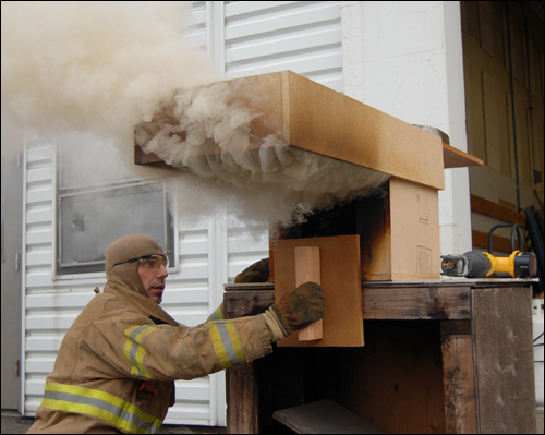
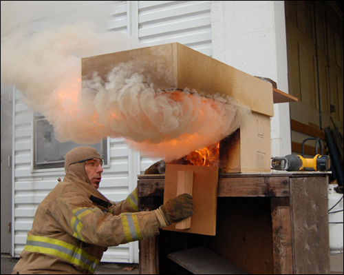
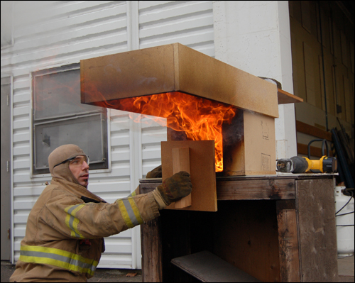
Smoke is fuel! The upper (hot gas) layer may contain a substantial mass of fuel that is ready to ignite. Flames exiting from a compartment door can ignite this fuel, resulting in rapid fire progression through the upper layer and into adjacent compartments. This phenomenon is demonstrated by CFBT-US Senior Instructor Trainer Matt Leech (LT Tualatin Valley Fire & Rescue) in Figures 1 through 3. While this demonstration involves use of a single compartment doll’s house and “porch roof”, the same phenomena can occur on a larger scale in any type of structure.

Figure 1. Accumulation of Fuel Overhead

dolls_house_pr_1

Figure 2. Extension of Flames and Ignition of Fuel Overhead

dolls_house_pr_2

Figure 3. Transition to Flaming Combustion Overhead

dolls_house_pr_3

This simple demonstration illustrates the hazards presented by smoke overhead, the importance of gas cooling, and good door entry technique. While often overlooked, recognition of this hazard is not new. “Smoke contains unburned fuel and when mixed with air in the proper proportion becomes a flammable mixture” (Layman, 1955).

When working under conditions of limited visibility, other sensory feedback becomes even more important to the nozzle operator. It is essential that firefighters become familiar with audible indicators of stream performance. Think about the sound of a straight stream hitting the ceiling or a wall versus the sound of a fog pattern applied into the hot gas layer (without significant contact with compartment linings). Would you be attuned to the difference in sound? This is important when you can’t see the pattern being discharged. Changes in temperature can also be an important indicator. However, it is important to remember that perceived temperature is also influenced by moisture. Excess steam production (from water hitting hot compartment linings) may make it seem like the temperature is rising, when this is due to increased moisture content in the smoke and air. If it seems like it is getting hotter, it is important to recognize if this is due to worsening fire conditions, or inappropriate water application.

Drill 6-Operating Without Visual Reference: This drill integrates door entry, hose handling, and nozzle techniques (pulsing and painting) under conditions with limited visibility. The drill can be conducted with the facepiece covered, in darkness, or using cold smoke (e.g., from a smoke machine). Learners should begin by using good door entry technique on an exterior door and then move through several compartments (preferably of different sizes), encountering several doors (some of which should be closed) along the way to the seat of the “fire”. Alternately, this drill can be used to practice hose handling and nozzle technique in the context of primary search with a hoseline (or in support of crews performing search).

Hose Handling & Nozzle Technique Drill 6 Instructional Plan

Indirect Attack

Indirect attack is a commonly misunderstood firefighting tactic. Common misconceptions include:

  • Indirect attack is only performed from the exterior of the building.
  • Indirect attack will push fire throughout the building.
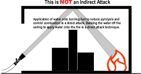
  • Indirect attack involves banking water off the ceiling to reach burning fuel that is inaccessible to direct application of water (see Figure 4).
  • Indirect attack and gas cooling is the same thing.

These statements are absolutely incorrect!

Figure 4. What Indirect Attack is NOT.

bank_shot

Several years ago I had a company officer that I worked with tell me that he had learned about a “new” fire control technique called the indirect attack at strategies and tactics class. I loaned him a small blue book titled Attacking and Extinguishing Interior Fires (Layman, 1955) and observed that this was not exactly a “new” idea.

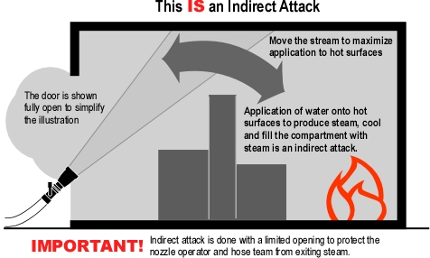
The concept of the indirect attack was an outgrowth of extensive study of fuel oil fires within confined spaces conducted by the instructor staff of the US Coast Guard Firefighting School at Fort McHenry in Baltimore, Maryland during World War II (Layman, 1955). The term indirect, referred to application of water into a hot compartment, but not directly onto the burning fuel. Conversion of water to steam absorbed a tremendous amount of energy and the expansion of steam filled the compartment (and potentially adjacent compartments which may also have been involved in fire).

In 1947, Lloyd Layman completed his service with the US Coast Guard and returned to duty as Fire Chief with the Parkersburg West Virginia Fire Department. Over the next two years, Layman and the members of his department worked to implement the concept of indirect attack for structural firefighting. In 1950 Chief Layman delivered a presentation titled Little Drops of Water (Layman, 1950) which outlined the adaptation of indirect attack for structural firefighting. In 1952 he completed Attacking and Extinguishing Interior Fires (Layman, 1955), a textbook that provided a more comprehensive look at indirect attack including several case studies based on incidents in Parkersburg where this approach had been used successfully in dealing with both residential and commercial fires.

As presented by Layman, the indirect attack was generally performed from the exterior of the building. However, it is important to recognize historical context. In the late 1940’s respiratory protection (when it was used) was often limited to All Service Masks, which used a filter mechanism to remove toxic products of combustion (to some extent), but could not be used in significantly oxygen deficient atmospheres.

Layman’s Error: Chief Layman made a number of extremely important and astute observations, particularly with regards to the tremendous cooling capacity of water when it is not only heated to its boiling point, but also converted to steam. However, one of the major assumptions related to indirect attack was in error. Layman states: “The injection of water into a highly heated atmosphere results in rapid generation of steam…[increasing] the atmospheric pressure within the space (p. 36-37). This points to the Chief’s assumption that steam produced as water was evaporated in the hot gas layer added to the total volume of gas and vapor within the space (i.e., the volume of steam was added to the volume of smoke and hot gases in the compartment). As discussed in Estimating Required Fire Flow: The Iowa Formula [LINK]; this is incorrect, water vaporized as it passes through the hot gas layer actually reduces total volume (due to cooling of the hot gases). On the other hand, water that is vaporized in contact with hot surfaces (that did not significantly cool the gases as it passed through the hot gas layer) adds to total volume as expanding steam is added to the volume of hot gases within the compartment. The difference between indirect attack and gas cooling will be explored in detail in my next post on Fire Stream Effectiveness and Efficiency.

Figure 5. Indirect Attack

indirect_attack

Drill 7-Indirect Attack from the Door: When faced with a fully developed fire in an enclosed area or a severely ventilation controlled fire (decay phase) that presents potential for a ventilation induced flashover or backdraft. Indirect attack may be an effective option for fire control. However, this tactic is not limited to exterior operations. Indirect attack can be initiated as part of the door entry procedure (exterior or interior doorway). If dynamic risk assessment indicates that entry is not viable due to fire conditions, the nozzle operator can use long pulses from the doorway (while the other member of the hose team controls the door) to apply water to hot surfaces, producing steam to gain control of conditions within the compartment prior to entry. This fire control method should be integrated with effective tactical ventilation (think planned, systematic, and coordinated).

Hose Handling & Nozzle Technique Drill 7 Instructional Plan

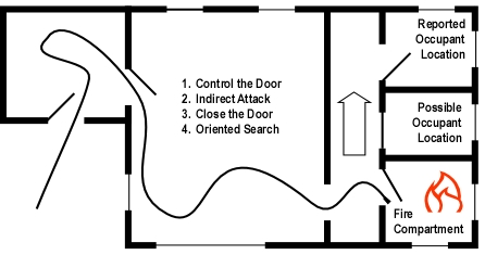
This approach can be extremely useful when the door to the fire compartment can be controlled and the hose team is presented with multiple priorities (persons reported and the need to control the fire to maintain the safety of interior operations). Figure 6 illustrates an example of how an indirect attack may be used when operating from the interior. In this scenario, the first arriving engine observes a fully developed fire in the bedroom on the A/D corner of a single family dwelling and receives information that an occupant is in the bedroom on the C/D corner. Rapidly developing fire conditions require immediate fire control. The crew makes entry from Side A, cools the hot gases overhead as they proceed to the fire compartment. As it is necessary to control the fire before proceeding past the involved compartment, they control the door, implement an indirect attack, and then extend an oriented search to locate the occupant while the nozzle operator protects the means of egress and maintains orientation for the firefighter performing the search in the adjacent compartments.

Figure 6. Application of Interior Indirect Attack.

indirect_bedroom_fire

While there are other tactical approaches that could be taken in this situation, use of an indirect attack allows the hose team to address both life safety (firefighters and occupants) and fire control tactical priorities.

Master Your Craft

Ed Hartin, MS, EFO, MIFIreE, CFO

References

Layman, L. (1955). Attacking and extinguishing interior fires. Boston, MA: National Fire Protection Association.

Layman, L. (1950). Little drops of water. Unpublished paper, presented at the Fire Department Instructors Conference (FDIC), Memphis, TN.

Reading the Fire 12

Wednesday, December 2nd, 2009

As discussed in prior Reading the Fire posts and the ongoing series examining fire behavior indicators (FBI), using the B-SAHF (Building, Smoke, Air Track, Heat, and Flame) organizing scheme, developing proficiency requires practice. This post provides an opportunity to exercise your skills using three video segments shot during an apartment fire.

Apartment Fire

At 2235 hours on November 19th the Bethlehem, PA fire department dispatched Engines 6, 9, 7, Ladder 2 & Chief 205 for an apartment fire with persons reported at 1992 Gatewood Lane. On arrival Engine 6 reported a working fire in an end-of-row unit. Tower Ladder (TL) 2 made two vertical ventilation (exhaust( openings in the roof above the fire. Chief 205 requested a second and then third alarm as the fire extended rapidly into the trussloft.

Download and the B-SAHF Worksheet.

The video segment was shot after TL 2 opened the roof.  First, describe what you observe in terms of the Building, Smoke, Air Track, Heat, and Flame Indicators; then answer the following five standard questions?

  1. What additional information would you like to have? How could you obtain it?
  2. What stage(s) of development is the fire likely to be in (incipient, growth, fully developed, or decay)?
  3. What burning regime is the fire in (fuel controlled or ventilation controlled)?
  4. What conditions would you expect to find inside this building (on floor 2 and in the attic)?
  5. How would you expect the fire to develop over the next two to three minutes

Crews use a combination of exterior attack (from the tower ladder and the roof) and interior attack from the second floor to control the fire.

  1. Did fire conditions progress as you anticipated?
  2. What concerns would you have about working on the top floor or roof in the involved area?
  3. How did vertical ventilation influence the fire in the trussloft (think about positives and negatives)?
  4. What alternatives to vertical ventilation of this lightweight roof system could be used to control the fire and prevent extension over uninvolved units?

While this incident had a positive outcome, it is important to recognize the potential for collapse of lightweight, engineered structural systems such as truss roof assemblies. Tactical success in one incident is not necessarily a predictor of future success should conditions be different (e.g., duration of fire impingement on structural members prior to arrival, burning regime, changes to the ventilation profile, etc.).

Master Your Craft

Remember the Past

Line of duty deaths involving extreme fire behavior has a significant impact on the family of the firefighter or firefighters involved as well as their department. Department investigative reports and NIOSH Death in the Line of Duty reports point out lessons learned from these tragic events. However, as time passes, these events fade from the memory of those not intimately connected with the individuals involved. It is important that we remember the lessons of the past as we continue our study of fire behavior and work to improve firefighter safety and effectiveness on the fireground.

November 23, 2006
Firefighter Steven Mitchell Solomon
Atlanta Fire Department, Georgia

Firefighter Solomon was working a 24-hour shift on Thanksgiving Day. Shortly after 2000hrs, Atlanta Fire-Rescue dispatched a full first-alarm assignment for a reported fire in an abandoned house. On arrival, companies encountered heavy smoke showing from a boarded-up single-story brick structure. As other crews removed plywood window coverings and forced entry through the front door, the crew of Engine 16 prepared to advance a 1-3/4inch attack line into the house. Firefighter Solomon was on the nozzle as the line was advanced inside. The attack team immediately encountered high temperature and zero-visibility conditions. Within seconds after they entered, the battalion chief arrived, assumed command, and ordered the companies to operate in a defensive strategy. Before the line could be backed out, the interior became enveloped in flames and the 3 firefighters from Engine 16 lost track of each other. Two of the firefighters managed to escape through the front door. Firefighters who were outside saw the silhouette of a firefighter, enveloped in flames, running past the front door and moving toward the rear of the house. The fire was quickly knocked down and crews made entry from both the front and rear to conduct a search. Firefighter Solomon was located almost immediately by a member who was using a thermal imaging camera and several firefighters quickly removed him from the dwelling. He was unconscious and critically burned. When he was found, Firefighter Solomon had removed his helmet, hood, and SCBA facepiece. One boot was also missing. Although he received immediate treatment from firefighter/paramedics on the scene and was transported within minutes to a level-one trauma center and regional burn unit, Firefighter Solomon died 6 days later without regaining consciousness.

Ed Hartin, MS, EFO, MIFIreE, CFO