Posts Tagged ‘NIST’

Wind Driven Fires

Sunday, February 26th, 2012

Seven Firefighters Injured

Seven firefighters were tragically injured in Prince George’s County Maryland on Friday, February 24, 2012. The fire broke out in the basement of a single-family, one-story house located at 6404 57th Avenue in Riverdale, MD shortly after 21:00 hours.
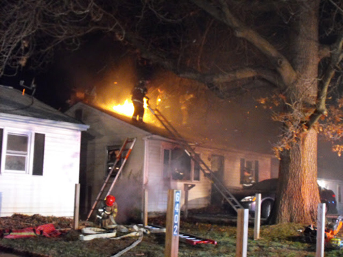
Note: View from Alpha-Bravo Corner street side. Photo by Billy McNeel.

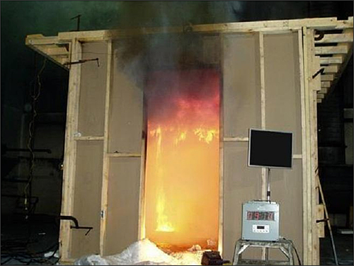
On arrival, Engine 807B reported a two-story, single family dwelling with fire showing from the basement level on Side Bravo. Seven members from Companies 807 (Riverdale) and 809 (Bladensburg) entered Floor 1 of the building on Side A (East Side) and within eight seconds were enveloped by untenable, wind driven fire conditions. Preliminary reports indicate that firefighters had initiated an interior attack on the fire when a sudden rush of air, fanned by high winds, entered from the rear of the house either from a door or window being opened or broken out. (Brady, 2012). A report on Monday, February 27 indicated that some of the firefighters ran to the back of the one-story home, then entered through a basement door while other members of their company opened the front door in search of a victim (FirefighterNation, 2012).

In a statement to Washington Post reporter J. Freedom du Lac (2012), Chief Marc Bashoor indicated that strong winds were gusting out of the west at up to 40, 45 mph, blowing directly into the burning basement, which had a west-facing door. “As soon as the guys opened the front door and advanced, it blew from the basement, up the steps and right out the front door,” Bashoor said. “It was like a blowtorch coming up the steps and out the door… Without that wind, the hot air and gases would have been venting out of the rear of the house,” he said. “The current of air essentially produced a chimney right up the steps and out the front door.” (Washington Post, 2012).

Firefighters Ethan Sorrell and Kevin O’Toole from Bladensburg Volunteer Fire Department remain in critical condition at Washington Hospital Center. Riverdale Volunteer, Michael McLary also remains hospitalized for injuries. The other injured firefighters were released and sent home Saturday evening according to the latest reports.

The wind-fueled fireball that injured seven Prince George’s County firefighters when it blew through the burning house they had just entered was “a freak occurrence,” a department spokesman, Mark Brady, said Saturday (du Lac, 2012).

Chris Naum at Command Safety has an excellent post examining the fire building and weather conditions at the time of the incident. See Residential Fire Injures Seven Firefighters: Wind Driven Conditions Suspected.

Freak Occurrence?

Dealing with an accident involving a serious injury or fatality is extremely difficult, particularly when the complete circumstances and eventual outcome is unknown. What may appear to be obvious in retrospect may also have been not so clear to the individuals engaged in emergency operations. However, one might ask if the fire behavior encountered at 6404 57th Avenue in Riverdale, MD was in fact a freak occurrence. A freak is defined as a thing or occurrence that is abnormal, markedly unusual or irregular.

The conditions encountered were markedly different than usually encountered in fires occurring in single family dwellings. However, the conditions described in this incident are not unusual when considered in light of the building configuration and wind conditions at the time of the incident. Wind, flow path, and burning regime (fuel or ventilation controlled) have a tremendous impact on fire behavior and potential for rapid fire progression resulting in untenable conditions.

Wind Driven Fires

On April 16, 2007 Technician Kyle Wilson of the Prince William Fire & Rescue lost his life in a wind driven fire occurring in a large, single family dwelling. In the introduction to the investigative report produced by Prince William Fire & Rescue examining this incident, Chief Kevin J. McGee states:

First, the impact the wind had on this event was significant. While weather conditions, and specifically wind, are often discussed in the firefighting environment of wildland fires, it does not receive the same attention and consideration in structure fires. This incident showed the dramatic and devastating effect the wind can have on the spread of fire in a building. The wind forced the fire into the building and caused the sudden change in fire conditions inside, including the “blowtorch” effect witnessed by the crews on the scene (Prince William County Fire Rescue, 2008)

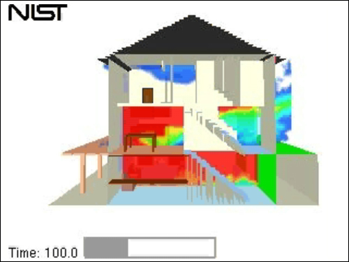
In January, the National Institute of Standards and Technology (NIST) released Simulation of the Dynamics of a Wind-Driven Fire in a Ranch-Style House-Texas (Barowy & Madrzykowski, 2012) examining fire behavior in the incident that took the lives of Houston Fire Department Captain James Harlow and Firefighter Damion Hobbs on April 12, 2009 while engaged in firefighting operations in a single family dwelling. This report emphasized that potential for wind driven fire conditions can occur in all types of buildings, including single-family residential structures.

NIST research (Madrzykowski & Kerber.(2009a, 2009b) has identified that wind driven fire conditions can be created with wind speeds as low as 4.5 m/s (10 mph) and that while structural fire departments have recognized the impact of wind on fire behavior, in general, standard operating guidelines (SOG) have not changed to address the risk of wind driven fires (Barowy & Madrzykowski, 2012).

Previous posts have examined NISTs research on the issue of wind driven fires:

Flow Path

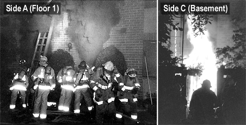
On May 30, 1999, Firefighters Anthony Phillips and Louis Matthews of the District of Columbia Fire Department (DCFD) died and two others were severely injured as a result of rapid fire progression while engaged in firefighting operations at 3146 Cherry Road, NE. The fire occurred in the basement of a two-story, middle of building, townhouse apartment. Crews entered on Floor 1, Side A and were caught in the flow path of hot smoke and flames when a sliding glass door was opened at the Basement Level on Side C. Previous posts examined this incident in detail:

More recently, the City of San Francisco Fire Department released an investigative report examining the circumstances surrounding the deaths of Lieutenant Vincent Perez and Firefighter/Paramedic Anthony Valerio on June 2, 2011 while operating at a fire in the basement of a two story home with two levels below grade. Failure of a basement window placed the Lieutenant and Firefighter in the flow path between the basement window and their entry point on Floor 1. The investigative report produced by the San Francisco Fire Department details their findings and recommendations related to this incident.

Safety Investigation Report Line-of-Duty Deaths, 133 Berkley Way, June 2, 2011, Box 8155, Incident #11050532

Structural Firefighting Under Wind Conditions

Research and fireground experience point to the following:

  • Building configuration including windows, doors, and open interior stairways can have a significant impact on development of a flow path from the fire to one or more exhaust points.
  • Introduction of additional air to a ventilation controlled fire (without concurrent fire suppression) will quickly result in increased heat release rate.
  • Creation of openings at and above the fire level which result in a flow path with an exhaust opening above the inlet will result in a rapid increase in heat release rate.
  • Thermal conditions in the flow path above the fire and/or downstream from the fire location or will quickly become untenable.
  • Even limited wind conditions can result in wind driven fire conditions.
  • These factors in combination are even more likely to result in rapid fire progression and untenable conditions in the downstream flow path.

It is essential that Firefighters and Fire Officers recognize the influence of ventilation on fire behavior and potential for wind driven fire conditions and adjust their strategies and tactics accordingly. The following guidance is based on recommendations developed through the NIST wind driven fires research as well as data from National Institute for Occupational Safety and Health (NIOSH) death in the line of duty reports and incident investigative reports by the Texas State Fire Marshals Office.

Potential for wind driven conditions increases directly with wind speed. When wind speeds exceed a gentle breeze (8-12 mph) consider the potential for wind driven fire conditions and apply the following strategic and tactical considerations (CWIFR District Board, 2011):

  • If potential for wind driven fire conditions is identified, this should be communicated to all companies and members working at the incident as a safety message.
  • When possible, operate from the exterior and apply water from upwind directly into the involved compartments prior to interior attack. Even low flow exterior streams applied from upwind can have a significant impact on controlling the fire prior to interior operations).
  • In a wind-driven fire, it is most important to use the wind to your advantage and attack the fire from the upwind side of the structure, especially if the upwind side is the burned side. Note that this may be contrary to conventional offensive tactics that place hoselines between the hazard presented by the fire and potential occupants and uninvolved property.
  • Avoid pressurization of the building without first establishing adequate exhaust openings (2-3 times larger than the inlet). Remember that wind can create the same (or greater) positive pressure as a blower used in positive pressure ventilation (PPV). Pressurization without adequate exhaust can result in extreme fire behavior. Note: This is particularly important when the fire is on the leeward (downwind) side of the building and entry is made from the windward (upwind) side of the building.
  • Consider controlling the flow path by using anti-ventilation such as door control and limiting the use of (horizontal and vertical) tactical ventilation prior to fire control. However, it is essential to remember that unplanned ventilation resulting from fire effects can have a significant impact on the ventilation profile and subsequent flow path(s).
  • Avoid working in the exhaust portion of the flow path (between the fire and exhaust opening) or potential flow paths (between the fire and potential exhaust openings). Unplanned ventilation from fire effects can suddenly change the interior thermal conditions.
  • Identify potential refuge areas, escape routes, and safety zones prior to and during interior operations. Taking refuge in a compartment with an intact and closed door may temporarily provide tenable conditions and a place of refuge until the fire can be controlled or another avenue of egress established.

References & Additional Reading

Brady, M. (2012). Seven firefighters injured battling Riverdale house fire. Retrieved February 26, 2012 from http://pgfdpio.blogspot.com/2012/02/seven-firefighters-injured-battling.html

Central Whidbey Island Fire & Rescue (CWIFR) District Board. (2011). Board minutes February 9, 2012. Coupeville, WA: Author. [Adoption of Purpose, Policy, and Scope of SOG 4.3.6 Structural Firefighting Under Wind Conditions]

District of Columbia (DC) Fire & EMS. (2000). Report from the reconstruction committee: Fire at 3146 Cherry Road NE, Washington DC, May 30, 1999. Washington, DC: Author.

du Lac, J. (2012). Blaze that injured 7 Prince George’s firefighters called ‘freak occurrence’. Retrieved February 26, 2012 from http://www.washingtonpost.com/local/blaze-that-injured-7-prince-georges-firefighters-called-freak-occurrence/2012/02/25/gIQAdGJMaR_story.html?hpid=z3

FirefighterNation. (2012). Critically burned in Maryland house fire, firefighters face long recovery. Retrieved February 28, 2012, from http://www.firefighternation.com/article/news-2/critically-burned-maryland-house-fire-firefighters-face-lengthy-recovery.

Madrzykowski , D. &  Barowy, A. (2012). Simulation of the dynamics of a wind-driven fire in a ranch-style house – Texas, TN 1729. Retrieved February 8, 2012 from http://www.nist.gov/customcf/get_pdf.cfm?pub_id=909779

Madrzykowski, D & Kerber, S. (2009a). Fire fighting tactics under wind driven conditions: Laboratory experiments, TN 1618. Retrieved February 8, 2012 from http://fire.nist.gov/bfrlpubs/fire09/PDF/f09002.pdf

Madrzykowski, D & Kerber, S. (2009b). Fire fighting tactics under wind driven fire conditions: 7-story building experiments, TN 1629. Retrieved February 8, 2012 from http://fire.nist.gov/bfrlpubs/fire09/PDF/f09015.pdf

Madrzykowski, D. & Vettori, R. (2000). Simulation of the Dynamics of the Fire at 3146 Cherry Road NE Washington D.C., May 30, 1999, NISTR 6510. August 31, 2009 from http://fire.nist.gov/CDPUBS/NISTIR_6510/6510c.pdf

National Institute for Occpational Safety and Health (NIOSH). (2008). Death in the line of duty…2007-12. Retrieved February 9, 2012 from http://www.cdc.gov/niosh/fire/pdfs/face200712.pdf

National Institute for Occpational Safety and Health (NIOSH). (2009). Death in the line of duty…2009-11. Retrieved February 9, 2012 from http://www.cdc.gov/niosh/fire/pdfs/face200911.pdf

National Institute for Occpational Safety and Health (NIOSH). (2009). Death in the line of duty…2007-29. Retrieved February 9, 2012 from http://www.cdc.gov/niosh/fire/reports/face200729.html

National Institute for Occupational Safety and Health (NIOSH). (1999). Death in the line of duty, Report 99-21. Retrieved August 31, 2009 from http://www.cdc.gov/niosh/fire/reports/face9921.html

Prince William County Department of Fire & Rescue. (2007). Line of duty death investigative report. Retrieved February 9, 2012 from http://www.google.com/url?sa=t&rct=j&q=&esrc=s&source=web&cd=2&ved=0CCgQFjAB&url=http%3A%2F%2Fwww.iaff.org%2Fhs%2FLODD_Manual%2FLODD%2520Reports%2FPrince%2520William%2520County%2C%2520VA%2520-%2520Wilson.pdf&ei=b3dKT8LyGfHSiALt5tnrDQ&usg=AFQjCNFBBTfVkWIREXw0-wbd978fWSoP8w&sig2=y6_OEeJvhFSggiKioMESaw

San Francisco Fire Department. (2012). Safety Investigation Report Line-of-Duty Deaths, 133 Berkley Way, June 2, 2011, Box 8155, Incident #11050532 Retrieved February 26, 2012 from http://statter911.com/files/2012/02/Safety-Investigation-133-Berkeley-Way-Printable.pdf

Texas State Fire Marshal’s Office. (2007). Firefighter fatality investigation, Investigation Number FY 07-02. http://www.tdi.texas.gov/reports/fire/documents/fmloddnoonday.pdf

Texas State Fire Marshal’s Office. (2009). Firefighter fatality investigation, Investigation Number FY 09- http://www.tdi.texas.gov/reports/fire/documents/fmloddhouston09.pdf

Kerber, S. (2011). Impact of ventilation on fire behavior in legacy and contemporary residential construction. Retrieved July 16, 2011 from http://www.ul.com/global/documents/offerings/industries/buildingmaterials/fireservice/ventilation/DHS%202008%20Grant%20Report%20Final.pdf

Decay Stage Fires:
Key Fire Behavior Indicators

Thursday, October 29th, 2009

As discussed in Flashover and Fully Developed Fires: Key Fire Behavior Indicators, providing additional oxygen to a ventilation controlled fire will result in a corresponding increase in heat release rate (HRR). This occurs because oxygen is required to release the chemical potential energy in fuel. The energy released per unit of mass of oxygen is remarkably consistent for both natural and synthetic organic (carbon containing) fuels.

Thorntons Rule specifies that one kilogram (1 kg) of oxygen is required to release 13.1 mega joules (MJ) of energy. Multiplying 13.1 MJ/kg of oxygen by 21% (the concentration of oxygen in air) provides a value of 2.751 MJ/kg of air. The Society of Fire Protection Engineering (SFPE) Handbook of Fire Protection Engineering (SFPE, 2002) rounds this value to 3.0 MJ/kg of air. For a more detailed discussion of Thorntons Rule and the relationship between fuel, oxygen, and energy release, see Fuel and Ventilation.

Decay Stage

A compartment fire may enter the decay stage as the available fuel is consumed or due to limited oxygen. As discussed in relation to flashover, a fuel package that does not contain sufficient energy or does not have a sufficient heat release rate to bring a compartment to flashover, will pass through each of the stages of fire development (but may not extend to other fuel packages). On a larger scale, without intervention an entire structure may reach full involvement and as fuel is consumed move into the decay stage. However, there is another, more problematic way for the fire to move into the decay stage. When the ventilation profile of the compartment or building does not provide sufficient oxygen, the fire may move into the decay stage. Heat release rate decreases as oxygen concentration drops. While temperature follows heat release rate, the temperature in decay stage fire may remain high for some time (particularly in well insulated, energy efficient buildings). This presents a significant threat as solid fuel packages continue to pyrolize and the involved compartment(s) may contain a high concentration of hot, pyrolized fuel, and flammable gaseous products of incomplete combustion.

Ventilation Controlled Fires

Under ventilation controlled conditions excess pyrolizate and flammable products of combustion present in smoke are a significant hazard to firefighters. Lets go back to the fire triangle to examine the nature of this threat. While fuel, heat, and oxygen are present in proportion to support combustion where the fire is burning, the heat of the fire is pyrolyzing more fuel vapor than the fire can consume. In addition, incomplete combustion results in production of flammable gases such as carbon monoxide. The speed of fire development is limited by the availability of atmospheric oxygen provided by the current ventilation profile of the compartment or building.

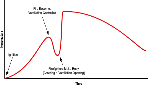
In his presentation, Fire Dynamics for the Fire Service, Dan Madrzykowski of the National Institute of Standards and Technology (NIST) discussed the increased potential for ventilation controlled, decay stage fires in todays modern, energy efficient structures. Dan presented the time temperature curve illustrated in Figure 1 to describe modern fire development and the potential influence of firefighting tactics.

Figure 1. Fire Development in the Modern Environment

modern_fire_development

Note: Adapted from National Institute of Standards and Technology (NIST) Fire Dynamics for the Fire Service, D. Madryzkowski.

The data in Figure 1 could be presented as HRR over time as well, but as HRR cannot be measured outside the lab, temperature is often used to describe fire development in full-scale tests. When the fire is burning in a ventilation controlled state, any increase in the supply of oxygen to the fire will result in an increase in heat release rate. Increase in ventilation may result from firefighters making entry into the building (the access point is a ventilation opening), tactical ventilation (performed by firefighters), or unplanned ventilation (e.g., failure of window glazing due to elevated temperature).

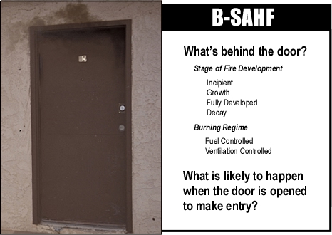
It is essential to recognize when the fire is, or may be ventilation controlled and the influence of planned and unplanned changes in ventilation profile. Most compartment fires that progress into the growth stage are ventilation controlled when the fire department arrives. A bi-directional air track (smoke out the top and air in the bottom) is often a significant indicator of a ventilation controlled fire, but what about before the door is open?

Figure 2. Assessment of Conditions at the Door

door_questions

As combustion becomes more incomplete, smoke production increases, color darkens, and optical density increases. However, these indicators may be subtle when observing fire conditions from the exterior. Assessment of conditions must continue after making entry. Smoke and air track indicators can be particularly useful in addressing the stage of fire development and burning regime when working inside. In addition, flames moving through the hot gas layer are a strong indicator of a ventilation controlled fire (as well as a threat to your safety which should be dealt with immediately).

Ventilation Induced Extreme Fire Behavior

When the fire is ventilation controlled, increased air supply to the fire will result in increased heat release rate and depending on conditions may result in extreme fire behavior such as flashover or backdraft. While both phenomena result from an increase in ventilation, vent induced flashover and backdraft are different phenomena. The conditions required for a ventilation induced flashover are 1) a compartment fire which has an insufficient HRR to reach flashover due to ventilation controlled combustion, and 2) insufficient concentration of excess pyrolizate and unburned products of incomplete combustion to result in a backdraft. While complex, the key determinant in the occurrence of a backdraft is likely to be the concentration of gas phase fuel within the compartment.

While these phenomena are different, both present a significant threat to firefighters. Rapid fire progress due to ventilation induced flashover or backdraft is not an instantaneous process. Depending on a number of variables such as the location of the fire, current level of involvement, temperature of the smoke (hot gas) layer, and extent of the increase in ventilation these rapid fire progress phenomenon may take some time to occur. However, when it does, fire development will be extremely rapid! Firefighters entering a compartment or building containing an under ventilated fire must be aware of and manage the hazards presented by the potential for rapid fire progress. Remember, many if not most fires that have progressed beyond the incipient stage before firefighters arrival are ventilation controlled and present the potential for rapid fire progress with increased ventilation (see Situational Awareness is Critical).

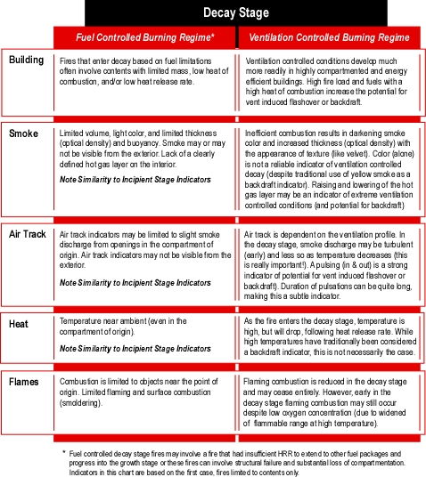
Figure 3 lists the fire behavior indicators related to ventilation controlled decay stage conditions and the potential for ventilation induced extreme fire behavior. It is important to note that there are not always clear distinctions in the visual indicators for vent induced flashover and backdraft.

Figure 3. FBI: Decay Stage

decay_indicators

Be Wary

Decay stage indicators can sometimes be subtle and conditions may not look too bad (maybe like an incipient or early growth stage fire if you are not paying close attention and consider the possibilities).

It is often assumed (incorrectly) that ventilation induced extreme fire behavior (flashover or backdraft) will occur immediately after an increase in ventilation. Depending on fire conditions and building configuration there may be a significant time lag between ventilation and resulting changes in fire behavior. When ventilation controlled decay conditions are indicated (or suspected), firefighters should move cautiously and take action to change conditions inside the building or compartment (e.g., gas cooling, ventilation).

You have responded to a fire in a one-story single family dwelling of wood frame construction. A fire which started in a bedroom on the Alpha Bravo corner of the structure has gone from fully developed to the decay stage due to a lack of oxygen as building openings (doors and windows) remain closed and intact.

  • What conditions would you expect to see from the exterior of the structure?
  • What indicators may be visible from the front door as you make entry?

A fire in the decay stage (particularly when this is due to limited oxygen) still presents a significant threat as conditions can change rapidly.

  • If the door at your entry point remains fully open, how will this influence fire behavior (assuming no other ventilation has been performed)?
  • How would fire behavior be influenced if a window (or windows) in the fire compartment are opened along with the door at your entry point?
  • What indicators would you anticipate observing as you traveled through the living room to the hallway leading to the bedroom?
  • What conditions would you find in the hallway outside the fire compartment?

After making entry, consider if conditions are different than you anticipated?

  • Why might this be the case?
  • What differences in conditions would be cause for concern?

Late Breaking News

I have been selected to serve as Fire Chief with the Central Whidbey Island Fire District in Washington and anticipate starting in my new position by mid November.

Over the next year I will also be serving on an advisory panel to assist Underwriters Laboratory with a research project on to examine the impact of ventilation on fire behavior in legacy and contemporary construction. Output from this project will include a formal technical report, articles in fire service publications, presentation to the fire service community, and a stand-alone web-based training module.

References

Society of Fire Protection Engineers (SFPE). (2002). The SFPE handbook of fire protection engineering (3rd ed.). Quincy, MA: National Fire Protection Association.

Madrzykowski, D. Fire dynamics for the fire service [PowerPoint Presentation], Gaithersburg, MD: National Institute of Standards and Technology.

Townhouse Fire: Washington, DC
Computer Modeling-Part 2

Monday, October 5th, 2009

This post continues study of an incident in a townhouse style apartment building in Washington, DC with examination of the extreme fire behavior that took the lives of Firefighters Anthony Phillips and Louis Mathews. As discussed in Townhouse Fire: Washington, DC-Computer Modeling Part I, this was one of the first cases where the NIST Fire Dynamics Simulator (FDS) software was used in forensic fire scene reconstruction (Madrzykowski and Vettori, 2000).

Quick Review

As discussed in prior posts, crews working on Floor 1 to locate the fire and secure the door to the stairwell were trapped and burned as a result of rapid progression of a fire in the basement up the open interior stairway after an exterior sliding glass door was opened to provide access to the basement. For detailed examination of incident operations and fire behavior, see:

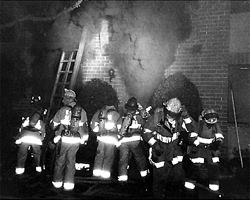
Figure 1. Conditions at Approximately 00:28

cherry_rd_sidebyside

Note: From Report from the Reconstruction Committee: Fire at 3146 Cherry Road NE, Washington DC, May 30, 1999, p. 29 & 32. District of Columbia Fire & EMS, 2000.

Smokeview

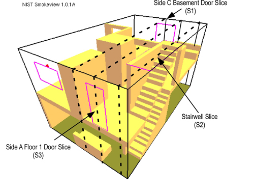
Smokeview is a visualization program used to provide a graphical display of a FDS model simulation in the form of an animation or snapshot. Snapshots illustrate conditions in a specific plane or slice within the building. Three vertical slices are important to understanding the fire dynamics involved in the Cherry Road incident: 1) midline of the door on Floor 1, Side A, 2) midline of the Basement Door, Side C, and midline of the Basement Stairwell (see Figure 2). Imagine that the building is cut open along the slice and that you can observe the temperature, oxygen concentration, or velocity of gas movement within that plane.

Figure 2. Perspective View of 3146 Cherry Road and Location of Slices

slices_sr

Note: From Simulation of the Dynamics of the Fire at 3146 Cherry Road NE Washington D.C., May 30, 1999, NISTR 6510 (p. 15) by Dan Madrzykowski and Robert Vettori, 2000, Gaithersburg, MD: National Institute for Standards and Technology.

In addition to having an influence on heat release rate, the location and configuration of exhaust and inlet openings determines air track (movement of smoke and air) and the path of fire spread. In this incident, the patio door providing access to the basement at the rear acted as an inlet, providing additional air to the fire. The front door and windows on the first floor opened for ventilation served as exhaust openings and provided a path for fire travel when the conditions in the basement rapidly transitioned to a fully developed fire.

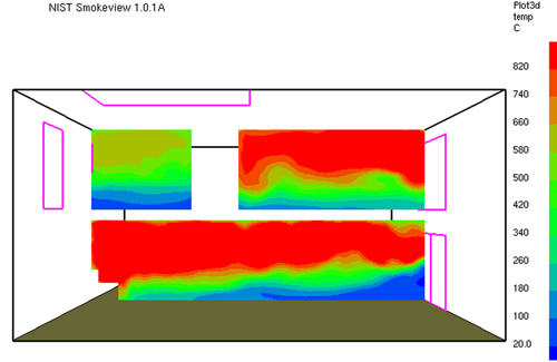
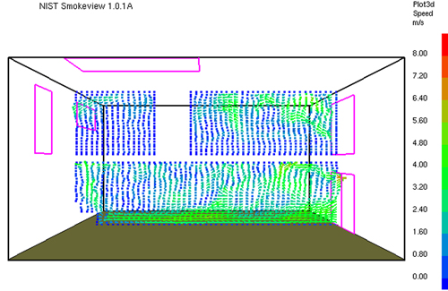
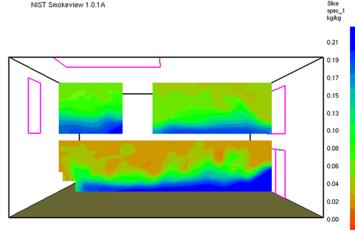
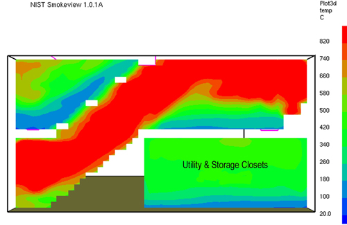
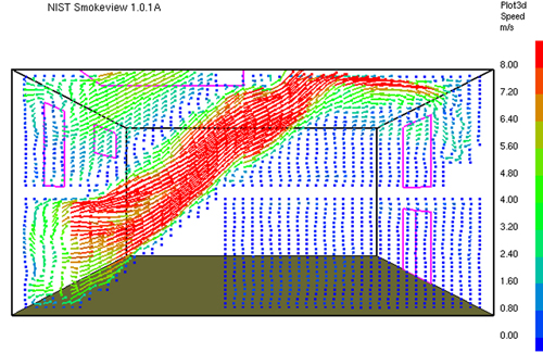
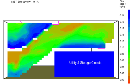
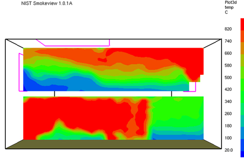
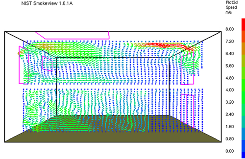
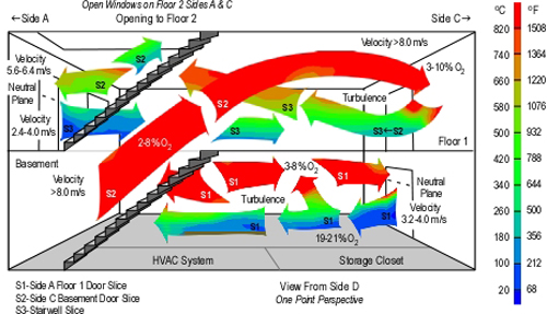
Figures 3-10 illustrate conditions at 200 seconds into the simulation, which relates to approximately 00:27 during the incident, the time at which the fire in the basement transitioned to a fully developed stage and rapidly extended up the basement stairway to Floor 1. Data is presented as a snapshot within a specific slice. Temperature and velocity data are provide for each slice (S1, S2, & S3 as illustrated in Figure 2).

Figure 3. Temperature Along Centerline of Basement Door Side C (S1) at 200 s

basement_door_temp_slice_sr

Note: From Simulation of the Dynamics of the Fire at 3146 Cherry Road NE Washington D.C., May 30, 1999, NISTR 6510 (p. 17) by Dan Madrzykowski and Robert Vettori, 2000, Gaithersburg, MD: National Institute for Standards and Technology.

Figure 4. Vector Representation of Velocity Along Centerline of Basement Door Side C (S1) at 200 s

basement_door_velocity_slice_sr

Note: From Simulation of the Dynamics of the Fire at 3146 Cherry Road NE Washington D.C., May 30, 1999, NISTR 6510 (p. 18) by Dan Madrzykowski and Robert Vettori, 2000, Gaithersburg, MD: National Institute for Standards and Technology.

Figure 5. Oxygen Concentration Along Centerline of Basement Door Side C (S1) at 200 s

basement_door_o2_slice_sr

Note: From Simulation of the Dynamics of the Fire at 3146 Cherry Road NE Washington D.C., May 30, 1999, NISTR 6510 (p. 23) by Dan Madrzykowski and Robert Vettori, 2000, Gaithersburg, MD: National Institute for Standards and Technology.

Figure 6. Temperature Slice Along Centerline of Basement Stairwell (S2) at 200 s

stairwell_temp_slice_sr

Note: From Simulation of the Dynamics of the Fire at 3146 Cherry Road NE Washington D.C., May 30, 1999, NISTR 6510 (p. 21) by Dan Madrzykowski and Robert Vettori, 2000, Gaithersburg, MD: National Institute for Standards and Technology.

Figure 7. Vector Representation of Velocity Along Centerline of Basement Stairwell (S2) at 200 s

stairwell_velocity_slice_sr

Note: From Simulation of the Dynamics of the Fire at 3146 Cherry Road NE Washington D.C., May 30, 1999, NISTR 6510 (p. 22) by Dan Madrzykowski and Robert Vettori, 2000, Gaithersburg, MD: National Institute for Standards and Technology.

Figure 8. Oxygen Concentration Along Centerline of Basement Stairwell (S2) at 200 s

stairwell_o2_slice_sr

Note: From Simulation of the Dynamics of the Fire at 3146 Cherry Road NE Washington D.C., May 30, 1999, NISTR 6510 (p. 24) by Dan Madrzykowski and Robert Vettori, 2000, Gaithersburg, MD: National Institute for Standards and Technology.

Figure 9. Temperature Slice Along Centerline of Floor 1 Door Side A (S3) at 200 s

front_door_temp_slice_sr

Note: From Simulation of the Dynamics of the Fire at 3146 Cherry Road NE Washington D.C., May 30, 1999, NISTR 6510 (p. 19) by Dan Madrzykowski and Robert Vettori, 2000, Gaithersburg, MD: National Institute for Standards and Technology.

Figure 10. Vector Representation of Velocity Along Centerline of Floor 1 Door Side A (S3) at 200 s

front_door_velocity_slice_sr

Note: From Simulation of the Dynamics of the Fire at 3146 Cherry Road NE Washington D.C., May 30, 1999, NISTR 6510 (p. 20) by Dan Madrzykowski and Robert Vettori, 2000, Gaithersburg, MD: National Institute for Standards and Technology.

Figure 11. Perspective Cutaway, Flow/Temperature, Velocity, and O2 Concentration

cherry_road_cutaway_sr

Figure 12. Thermal Exposure Limits in the Firefighting Environment

thermal_environment

Note: Adapted from Measurements of the firefighting environment. Central Fire Brigades Advisory Council Research Report 61/1994 by J.A. Foster & G.V. Roberts, 1995. London: Department for Communities and Local Government and Thermal Environment for Electronic Equipment Used by First Responders by M.K. Donnelly, W.D. Davis, J.R. Lawson, & M.J. Selepak, 2006, Gaithersburg, MD: National Institute of Standards and Technology.

Compartment Fire Thermal Hazards

The temperature of the atmosphere (i.e., smoke and air) is a significant concern in the fire environment, and firefighters often wonder or speculate about how hot it was in a particular fire situation. However, gas temperature in the fire environment is a bit more complex than it might appear on the surface and is only part of the thermal hazard presented by compartment fire.

Tissue temperature and depth of penetration determine the severity of a thermal burn. Temperature and penetration are dependent on the amount of energy absorbed and the duration of the thermal insult as well as the properties of human tissue. In a compartment fire, firefighters absorb energy from any substance that has a temperature above 37o C (98.6o F), including hot compartment linings, contents, the hot gas layer, and flames. The dominant mechanisms of heat transfer involved in this process are convection and radiation (although conduction through personal protective equipment is also a factor to be considered).

The total thermal energy received is described in joules per unit area. However, the speed or rate of energy is transferred may be more important when assessing thermal hazard. Heat (thermal) flux is used to define the rate of heat transfer and is expressed in kW/m2 (Btu/hr/ft2).

One way to understand the interrelated influence of radiant and convective heat transfer is to consider the following scenario. Imagine that you are standing outside in the shade on a hot, sunny day when the temperature is 38o C (100o F). As the ambient temperature is higher than that of your body, energy will be transferred to you from the air. If you move out of the shade, your body will receive additional energy as a result of radiant heat transfer from the sun.

Convective heat transfer is influenced by gas temperature and velocity. When hot gases are not moving or the flow of gases across a surface (such as your body or personal protective equipment) is slow, energy is transferred from the gases to the surface (lowering the temperature of the gases, while raising surface temperature). These lower temperature gases act as an insulating layer, slowing heat transfer from higher temperature gases further away from the surface. When velocity increases, cooler gases (which have already transferred energy to the surface) move away and are replaced by higher temperature gases. When velocity increases sufficiently to result in turbulent flow, hot gases remain in contact with the surface on a relatively constant basis, increasing convective heat flux.

Radiant heat transfer is influenced by proximity and temperature of the radiating body. Radiation increases by a factor of four when distance to the hot material is reduced by half. In addition, radiation increases exponentially (as a function of the fourth power) as absolute temperature increases.

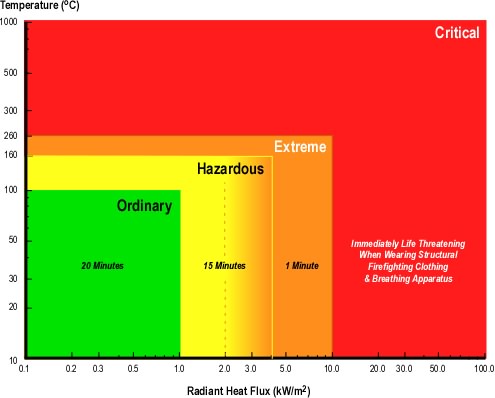
Thermal hazard may be classified based on hot gas temperature and radiant heat flux (Foster & Roberts, 1995; Donnelly, Davis, Lawson, & Selpak, 2006) with temperatures above 260o C (500o F) and/or radiant heat flux of 10 kW/m2 (3172 Btu/hr/ft2) being immediately life threatening to a firefighter wearing a structural firefighting ensemble (including breathing apparatus). National Institute of Standards and Technology (NIST) experiments in a single compartment show post flashover gas temperatures in excess of 1000o C (1832o F) and heat flux at the floor may exceed 170 kW/m2 (Donnelly, Davis, Lawson, & Selpak, 2006). Post flashover conditions in larger buildings with more substantial fuel load may be more severe!

Figure 11 integrates temperature, velocity, and oxygen concentration data from the simulation (Figures 3-10). Detail and accuracy is sacrificed to some extent in order to provide a (somewhat) simpler view of conditions at 200 seconds into the simulation (approximately 00:27 incident time). Note that as in individual slices, data is presented as a range due to uncertainty in the computer model.

Alternative Model

In addition to modeling fire dynamics based on incident conditions and tactical operations as they occurred, NIST also modeled the incident with a slightly different ventilation profile.

The basic input for the alternate simulation was the same as the simulation of actual incident conditions. Ventilation openings and timing was the same, with one exception; the sliding glass door on Floor 1, Side C was opened at 120 s into the simulation. Conditions in the basement during the alternative simulation were similar to the first. However, on Floor 1, the increase in ventilation provided by the sliding glass door on Side C resulted in a shallower hot gas layer and cooler conditions at floor level. A side-by-side comparison of the temperature gradients in these two simulations is provided in Figure 13.

Figure 13. Comparison of Temperature Gradients Along Centerline of Basement Stairwell (S2) at 200 s

stairwell_slice_comparison_sr1

Note: Adapted from Simulation of the Dynamics of the Fire at 3146 Cherry Road NE Washington D.C., May 30, 1999, NISTR 6510 (p. 21 & 27) by Dan Madrzykowski and Robert Vettori, 2000, Gaithersburg, MD: National Institute for Standards and Technology.

The NIST Report (Madrzykowski & Vettori, 2000) identified that the significant difference between these two simulations is in the region close to the floor. In the alternative simulation (Floor 1, Side C Sliding Glass Door Open) between the doorway to the basement and the sofa, the temperatures from approximately 0.6 m (2 ft) above the floor, to floor level are in the range of 20 C to 100 C (68F to 212 F), providing at least an 80 C (176 F) temperature reduction.

While this is a considerable reduction in gas temperature, it is essential to also consider radiant heat flux from the hot gas layer. Given the temperature of the hot gases from the ceiling level to a depth of approximately 3′ (0.9 m), the heat flux at the floor would likely have been in the range of 15-20 kW/m2 (or greater).

Questions

  1. Temperatures vary widely at a given elevation above the floor. Consider the slices illustrated in Figures 3, 6, and 9, and identify factors that may have influenced these major differences in temperature.
  2. How might the variations in temperature illustrated in Figures 3, 6, and9 and location of Firefighters Phillips (basement doorway), Mathews (living room, C/D corner), and Morgan (between Phillips & Mathews) have influenced their injuries?
  3. Examine the velocity of gas movement illustrated in Figures 4, 7, and 10 and integrated illustration conditions in Figure 11. How does this correlate to the photos in Figure 1 illustrating incident conditions at approximately 00:28?
  4. Explain how the size and configuration of ventilation openings resulted in a bi-directional air track at the basement door on Side C.
  5. How did the velocity of hot gases in the stairwell and living room influence the thermal insult to Firefighters Phillips, Mathews, and Morgan? What factors caused the high velocity flow of gases from the basement stairwell doorway into the living room?
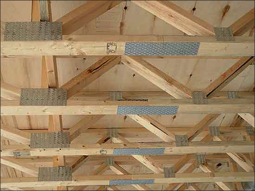
  6. Rescue 1B noted that the floor in the living room was soft while conducting primary search at approximately 00:30. Why didn’t the parallel chord trusses in the basement fail sooner? Is there a potential relationship between fire behavior and performance of the engineered floor support system in this incident?
  7. How might stability of the engineered floor support system have differed if the sliding glass door in the basement had failed prior to the fire departments arrival? Why?
  8. How might the double pane glazing on the windows and sliding glass doors have influenced fire development in the basement? How might fire development differed if these building openings had been fitted with single pane glazing?
  9. What was the likely influence of turbulence in the flow of hot gases and cooler air on combustion in the basement? What factors influenced this turbulence (examine Figures 4, 7, and 10) illustrating velocity of flow and floor plan illustrated in conjunction with the second question)?
  10. How did conditions in the area in which Firefighters Phillips, Mathews, and Morgan were located correlate to the thermal exposure limits defined in Figure 12? How did this change in the alternate scenario? Remember to consider both temperature and heat flux.

Extended Learning Activity

The Cherry Road case study provides an excellent opportunity to develop an understanding of the influence of building factors, burning regime, ventilation, and tactical operations on fire behavior. These lessons can be extended by comparing and contrasting this case with other cases such as the 1999 residential fire in Keokuk, Iowa that took the lives Assistant Chief Dave McNally, Firefighter Jason Bitting, and Firefighter Nathan Tuck along with three young children. For information on this incident see NIOSH Death in the Line of Duty Report F2000-4, NIST report Simulation of the Dynamics of a Fire in a Two Story Duplex, NIST IR 6923.and video animation of Smokeview output from modeling of this incident

Master Your Craft

Ed Hartin, MS, EFO, MIFireE, CFO

References

District of Columbia (DC) Fire & EMS. (2000). Report from the reconstruction committee: Fire at 3146 Cherry Road NE, Washington DC, May 30, 1999. Washington, DC: Author.

Madrzykowski, D. & Vettori, R. (2000). Simulation of the Dynamics of the Fire at 3146 Cherry Road NE Washington D.C., May 30, 1999, NISTR 6510. August 31, 2009 from http://fire.nist.gov/CDPUBS/NISTIR_6510/6510c.pdf

National Institute for Occupational Safety and Health (NIOSH). (1999). Death in the line of duty, Report 99-21. Retrieved August 31, 2009 from http://www.cdc.gov/niosh/fire/reports/face9921.html

Growth Stage Fires:
Key Fire Behavior Indicators

Thursday, October 1st, 2009

The last post in this series, Incipient Fires: Key Fire Behavior Indicators reviewed stages of fire development (i.e., incipient, growth, fully developed, and decay), burning regimes (i.e., fuel and ventilation controlled) and identified key indicators used to recognize incipient stage fires. This post examines key indicators to identify growth stage fires and their burning regime.

Growth Stage & Burning Regime

Like many concepts in fire dynamics there is a bit of ambiguity between where the incipient stage ends and the growth stage begins. For firefighters, this distinction is important as growth stage fires are deemed to present an Immediately Dangerous to Life and Health (IDLH) threat based on the increasing speed of fire development, toxicity and thermal environment. This triggers Occupational Safety and Health Administration (OSHA) respiratory protection regulations requirements for “two-in/two-out”. Key characteristics of a growth stage fire include increasing heat release rate (HRR), significantly increasing temperature within the compartment.

The speed of fire development in the growth stage may be limited by fuel characteristics and configuration or ventilation. Typically compartment fires in the early growth stage are fuel controlled. However, if the compartment is small and/or has limited ventilation, continued combustion will result in slowing fire development as the fire enters the ventilation controlled burning regime. Recognizing the ventilation controlled burning regime is critical as increases in ventilation will result in increased HRR. This is not necessarily a major problem unless it is unanticipated or firefighters do not have the capacity to control this additional HRR.

A Single Compartment

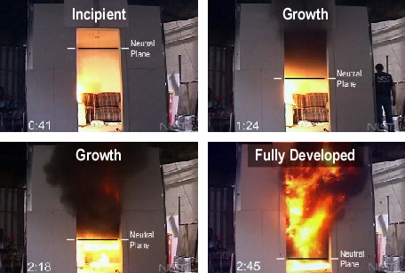
While most buildings have multiple, interconnected rooms, providing a complex environment for fire development, it is useful to begin by examining fire development in a single compartment (see Figure 1)

Figure 1. Fire Development in a Single Compartment.

neutral_plane_burning_regime

Note: Photos adapted from National Institute of Standards and Technology (NIST) ISO-Room/Living Room Flashover [Digital Video Disk].

As a compartment fire develops hot products of combustion and entrained air rise in a plume from the burning fuel package. When the plume reaches the ceiling, hot gases begin to move horizontally, forming a ceiling jet. As the fire progresses through the incipient stage and into growth, additional fuel will become involved and the heat release rate from the fire will increase. While thermal conditions can be considerably more complex, gas temperatures within the compartment may be described as existing in two layers: A hot layer extending down from the ceiling and a cooler layer down towards the floor. Convection resulting from plume and ceiling jet along with radiant heat from the fire and hot particulates in the smoke increases the temperature of the compartment linings and other items in the compartment.

The fire can continue to grow through flame spread or by ignition of other fuel within the compartment. As flames in the plume reach the ceiling they will bend and begin to extend horizontally. Pyrolysis products and flammable byproducts of incomplete combustion in the hot gas layer will ignite and continue this horizontal extension across the ceiling. As the fire moves further into the growth stage, the dominant heat transfer mechanism within the fire compartment shifts from convection to radiation. Radiant heat transfer increases heat flux (transfer of thermal energy) at floor level.

As gases within the compartment are heated they expand and when confined by the compartment increase in pressure. Higher pressure in this layer causes it to push down within the compartment and out through openings. The pressure of the cool gas layer is lower, resulting in inward movement of air from outside the compartment. At the point where these two layers meet, as the hot gases exit through an opening, the pressure is neutral. The interface of the hot and cool gas layers at an opening is commonly referred to as the neutral plane.

If the compartment is sealed (e.g., door closed and windows intact), the fire may become ventilation controlled, slowing the increase in HRR and temperature, and eventually moving the fire into the decay stage (defined by decreasing HRR). However, if the compartment is not sealed (e.g., open door), the fire may become ventilation controlled, but HRR can continue to increase as smoke flows out of the involved compartment and air from the remainder of the building flows in at floor level, providing the oxygen necessary for continued combustion.

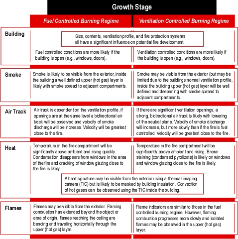
In growth stage fires, fire behavior indicators are often visible from the exterior of the building. However, depending on fire location and building factors (e.g., energy efficiency, ventilation profile) these indicators may be fairly obvious or quite subtle. Growth stage indicators are listed in Figure 2

Figure 2. FBI: Growth Stage

growth_indicators

In Incipient Fires: Key Fire Behavior Indicators you were presented with a residential fire scenario as an opportunity to give some thought to how key fire behavior indicators may present. Consider

Use the B-SAHF model to help you frame your answers.

You have responded to a fire in a one-story single family dwelling of wood frame construction. A growth stage fire is burning a bedroom on the Alpha Bravo corner of the structure. The fire involves a plastic trash can, the bed, and night stand.

  • What conditions would you expect to see from the exterior of the structure?
  • What indicators may be visible from the front door as you make entry?
  • What indicators would you anticipate observing as you traveled through the living room and down the hallway to the bedroom where the fire is located?
  • What conditions would you find in the bedroom?

As the fire moves through the growth stage, the speed at which conditions change increases rapidly. After making entry, consider if conditions are different than you anticipated?

  • Why might this be the case?
  • What differences in conditions would be cause for concern?

Master Your Craft

More to Follow

The next post in this series will continue examination of the relationship between the B-SAHF indicators, fire development, and burning regime by connecting to the parallel series of posts on flashover and examining fully developed fires.

Ed Hartin, MS, EFO, MIFireE, CFO

References

National Institute of Standards and Technology. (2005). ISO-room/living room flashover [digital video disk]. Gaithersburg, MD: Author.

Townhouse Fire: Washington, DC:
Computer Modeling

Monday, September 28th, 2009

This post continues study of an incident in a townhouse style apartment building in Washington, DC with examination of the extreme fire behavior that took the lives of Firefighters Anthony Phillips and Louis Mathews.

A Quick Review

Prior posts in this series, Fire Behavior Case Study of a Townhouse Fire: Washington, DC, Townhouse Fire: Washington, DC-What Happened,and Townhouse Fire: Washington, DC-Extreme Fire Behavior examined the building and initial tactical operations at this incident. The fire occurred in the basement of a two-story, middle of building, townhouse apartment with a daylight basement. This configuration provided at grade entrances to Floor 1 on Side A and the Basement on Side C.

Engine 26, the first arriving unit reported heavy smoke showing from Side A and observed a bi-directional air track at the open front door. Engines 26 and 10 operating from Side A deployed hoselines into the first floor to locate the fire. Engine 17, the second due engine, was stretching a hoseline to Side C, but had insufficient hose and needed to extend their line. Truck 4, the second due truck, operating from Side C opened a sliding glass door to the basement to conduct search and access the upper floors (prior to Engine 17’s line being in position). When the door on Side C was opened, Truck 4 observed a strong inward air track. As Engine 17 reached Side C (shortly after Rescue 1 and a member of Truck 4 entered the basement) and asked for their line to be charged. Engine 17 advised Command that the fire was small.

Conditions changed quickly after the door on Side C was opened, as conditions in the basement rapidly transitioned to a fully developed fire with hot gases and flames extending up the interior stairway trapping Firefighters Phillips, Mathews, and Morgan. Confusion about building configuration (particularly the number of floors and location of entry points on Side A and C) delayed fire attack due to concern for opposing hoselines.

Modeling of the Cherry Road Incident

National Institute for Standards and Technology (NIST) performed a computer model of fire dynamics in the fire at 3146 Cherry Road (Madrzykowski and Vettori, 2000) using the NIST Fire Dynamics Simulator (FDS) software. This is one of the first cases where FDS was used in forensic fire scene reconstruction.

Fire Modeling

Fire modeling is a useful tool in research, engineering, fire investigation, and learning about fire dynamics. However, effective use of this tool and the information it provides requires understanding of its capabilities and limitations.

Models, such as the National Institute of Standards and Technology (NIST) Fire Dynamics Simulator (FDS) relay on computational fluid dynamics (CFD). CFD models define the fire environment by dividing it into small, rectangular cells. The model simultaneously solves mathematical equations for combustion, heat transfer, and mass transport within and between cells. When used with a graphical interface such as NIST Smokeview, output can be displayed in a three-dimensional (3D) visual format.

Models must be validated to determine how closely they match reality. In large part this requires comparison of model output to full scale fire tests under controlled conditions. When used for forensic fire scene reconstruction, it may not be feasible to recreate the fire to test the model. In these situations, model output is compared to physical evidence and interview data to determine how closely key aspects of model output matched events as they occurred. If model output reasonably matches events as they occurred, it is likely to be useful in understanding the fire dynamics involved in the incident.

It is crucial to bear in mind that fire models do not provide a reconstruction of the reality of an event. They are simplified representation of reality that will always suffer from a certain lack of accuracy and precision. Under the condition that the user is fully aware of this status and has an extensive knowledge of the principles of the models, their functioning, their limitations and the significance attributed to their results, fire modeling becomes a very powerful tool (Delemont & Martin, J., 2007, p. 134).

FDS output included data on heat release rate, temperature, oxygen concentration, and velocity of gas (smoke and air) movement within the townhouse. As indicated above, model output is an approximation of actual incident conditions.

In large scale fire tests (McGrattan, Hamins, & Stroup, 1998, as cited in Madrzykowski and Vettori, 2000), FDS temperature predictions were found to be within 15% of the measured temperatures and FDS heat release rates were predicted to within 20% of the measured values. For relatively simple fire driven flows such as buoyant plumes and flows through doorways, FDS predictions are within experimental uncertancies (McGrattan, Baum, & Rehm, 1998, as cited in Madrzykowski and Vettori, 2000).

Results presented in the NIST report on the fire at 3146 Cherry Road were presented as ranges to account for potential variation between model output and actual incident conditions.

Heat release rate is dependent on the characteristics and configuration of the fuel packages involved and available oxygen. In a compartment fire, available oxygen is dependent on the ventilation profile (i.e., size and location of compartment openings). The ventilation profile can change over time due to the effects of the fire (e.g., failure of window glazing) as well as human action (i.e., doors left open by exiting occupants, tactical ventilation, and tactical anti-ventilation)

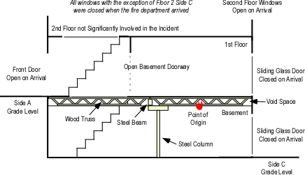
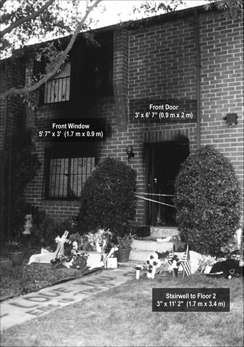
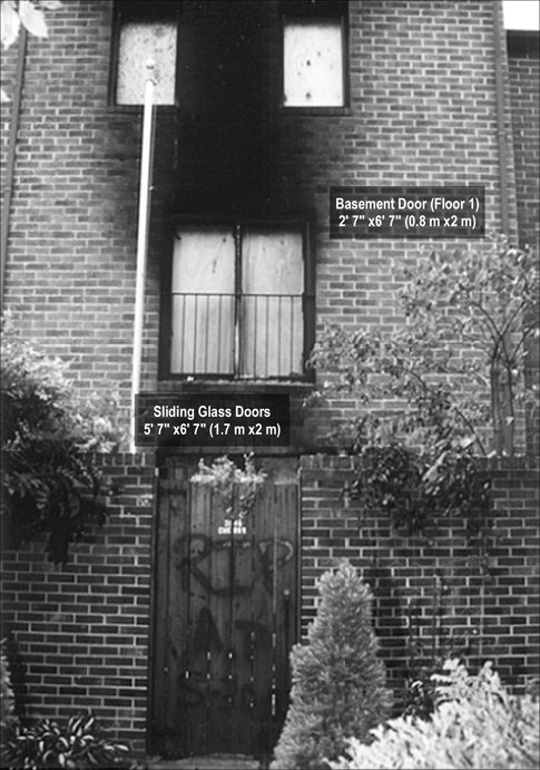
In this incident there were a number of changes to the ventilation profile. Most significant of which were, 1) the occupant opened the second floor windows on Side C (see Figure 3), 2) the occupant left the front door open as they exited (see Figures 1 &2 ), 3) tactical ventilation of the first floor window on Side A, and opening of the sliding glass door in the basement on Side C (see Figures 1-3). In addition, the open door in the basement stairwell and open stairwell between the Floors 1 and 2 also influenced the ventilation profile (see Figure 1).

Figure 1. Cross Section of 3146 Cherry Road NE

cherry_road_cross_section

Figure 2. Side A 3146 Cherry Road NE

side_a_post_fire

Figure 3. Side C 3146 Cherry Road NE

side_c_post_fire

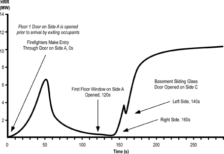
Figure 4 illustrates the timing of changes to the ventilation profile and resulting influence on heat release rate in modeling this incident. A small fire with a specific heat release rate (HRR) was used to start fire growth in the FDS simulation. In the actual incident it may have taken hours for the fire to develop flaming combustion and progression into the growth stage. Direct comparison between the simulation and incident conditions began at 100 seconds into the simulation which corresponds to approximately 00:25 during the incident.

Figure 4. FDS Heat Release Rate Curve

cherry_road_hrr_curve

Note: Adapted from Simulation of the Dynamics of the Fire at 3146 Cherry Road NE Washington D.C., May 30, 1999, NISTR 6510 (p. 14) by Dan Madrzykowski and Robert Vettori, 2000, Gaithersburg, MD: National Institute for Standards and Technology.

Questions

The following questions are based on heat release rate data from the FDS model presented in Figure 4.

  1. What was the relationship between changes in ventilation profile and heat release rate?
  2. What would explain the rapid increase in heat release rate after the right side of the basement sliding glass door is opened?
  3. Why might the heat release rate have dropped slightly prior to opening of the left side of the basement sliding glass door?
  4. Why did the heat release rate again increase rapidly to in excess of 10 MW after the left side of the basement sliding glass door was opened?
  5. How does data from the FDS model correlate to the narrative description of events presented in prior posts about this incident (Fire Behavior Case Study of a Townhouse Fire: Washington, DC, Townhouse Fire: Washington, DC-What Happened,and Townhouse Fire: Washington, DC-Extreme Fire Behavior)?

More to Follow

In addition to heat release rate data the computer modeling of this incident provided data on temperature, oxygen concentration, and gas velocity. Visual presentation of this data provides a more detailed look at potential conditions inside the townhouse during the fire. The next post in this series will present and examine graphic output from Smokeview to aid in understanding the fire dynamics and thermal environment encountered during this incident.

Master Your Craft

Ed Hartin, MS, EFO, MIFireE, CFO

References

District of Columbia (DC) Fire & EMS. (2000). Report from the reconstruction committee: Fire at 3146 Cherry Road NE, Washington DC, May 30, 1999. Washington, DC: Author.

Madrzykowski, D. & Vettori, R. (2000). Simulation of the Dynamics of the Fire at 3146 Cherry Road NE Washington D.C., May 30, 1999, NISTR 6510. August 31, 2009 from http://fire.nist.gov/CDPUBS/NISTIR_6510/6510c.pdf

National Institute for Occupational Safety and Health (NIOSH). (1999). Death in the line of duty, Report 99-21. Retrieved August 31, 2009 from http://www.cdc.gov/niosh/fire/reports/face9921.html

Townhouse Fire: Washington, DC
Extreme Fire Behavior

Monday, September 21st, 2009

This post continues study of an incident in a townhouse style apartment building in Washington, DC with examination of the extreme fire behavior that took the lives of Firefighters Anthony Phillips and Louis Mathews.

A Quick Review

Prior posts in this series, Fire Behavior Case Study of a Townhouse Fire: Washington, DC and Townhouse Fire: Washington, DC-What Happened examined the building and initial tactical operations at this incident. The fire occurred in the basement of a two-story, middle of building, townhouse style apartment with a daylight basement. This configuration provided an at grade entrance to the Floor 1 on Side A and at grade entrance to the Basement on Side C.

Engine 26, the first arriving unit reported heavy smoke showing from Side A and observed a bi-directional air track at the open front door. First alarm companies operating on Side A deployed hoselines into the first floor to locate the fire. Engine 17, the second due engine, was stretching a hoseline to Side C, but had insufficient hose and needed to extend their line. Truck 4, the second due truck, operating from Side C opened a sliding glass door to the basement to conduct search and access the upper floors (prior to Engine 17’s line being in position). When the door on Side C was opened, Truck 4 observed a strong inward air track. As Engine 17 reached Side C (shortly after Rescue 1 and a member of Truck 4 entered the basement) and asked for their line to be charged, and Engine 17 advised Command that the fire was small.

Extreme Fire Behavior

Proceeding from their entry point on Side C towards the stairway to Floor 1 on Side A, Rescue 1B and the firefighter from Truck 4 observed fire burning in the middle of the basement room. Nearing the stairs, temperature increased significantly and they observed fire gases in the upper layer igniting. Rescue 1B and the firefighter from Truck 4 escaped through the basement doorway on Side C as the basement rapidly transitioned to a fully developed fire.

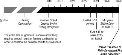
Figure 1. Timeline Leading Up to the Extreme Fire Behavior Event

short_timeline_sr

The timeline illustrated in Figure 1 is abbreviated and focuses on a limited number of factors. A detailed timeline, inclusive of tactical operations, fire behavior indicators, and fire behavior is provided in a subsequent section of the case.

After Engine 17’s line was charged, the Engine 17 officer asked Command for permission to initiate fire attack from Side C. Command denied this request due to lack of contact with Engines 26 and 10 and concern regarding opposing hoselines. Due to their path of travel around Side B of the building, Engine 17 had not had a clear view of Side A and thought that they were at a doorway leading to Floor 1 (rather than the Basement). At this point, neither the companies on Side C nor Command recognized that the building had three levels on Side C and two levels on Side A.

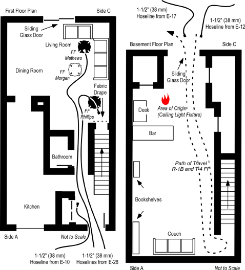
At this point crews from Engine 26 and 10 are operating on Floor 1 and conditions begin to deteriorate. Firefighter Morgan (Engine 26) observed flames at the basement door in the living room (see Figure 8 which illustrates fire conditions in the basement as seen from Side C). Firefighter Phillips (Engine 10) knocked down visible flames at the doorway, but conditions continued to deteriorate. Temperature increased rapidly while visibility dropped to zero.

As conditions deteriorated, Engine 26’s officer feels his face burning and quickly exits (without notifying his crew). In his rapid exit through the hallway on Floor 1, he knocked the officer from Engine 10 over. Confused about what was happening Engine 10’s officer exited the building as well (also without notifying his crew). Engine 26’s officer reports to Command that Firefighter Mathews was missing, but did not report that Firefighter Morgan was also missing. Appearing dazed, Engine 10’s officer did not report that Firefighter Phillips was missing.

Figure 2. Conditions on Side C at Aproximately 00:28

fire_side_c_sr

Note: From Report from the Reconstruction Committee: Fire at 3146 Cherry Road NE, Washington DC, May 30, 1999, p. 32. District of Columbia Fire & EMS, 2000.

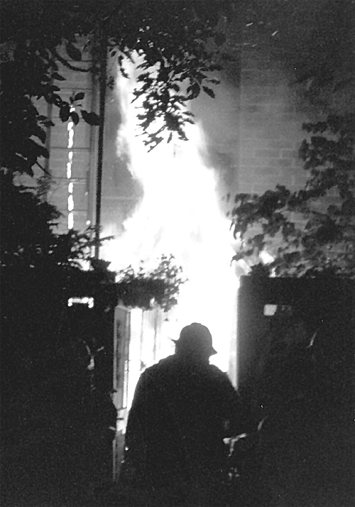
Figure 3. Conditions on Side A at Aproximately 00:28

fire_side_a_sr

Note: From Report from the Reconstruction Committee: Fire at 3146 Cherry Road NE, Washington DC, May 30, 1999, p. 29. District of Columbia Fire & EMS, 2000.

Firefighter Rescue Operations

After the exit of the officers from Engine 26 and Engine 10, the three firefighters (Mathews, Phillips, and Morgan) remained on Floor 1. However, neither Command (Battalion 1) nor a majority of the other personnel operating at the incident recognized that the firefighters from Engines 26 and 10 had been trapped by the rapid extension of fire from the Basement to Floor 1 (see Figure 4).

While at their apparatus getting a ladder to access the roof from Side B, Truck 4B observed the rapid fire development in the basement and pulled a 350′ 1-1/2″ (107 m 38 mm) line from Engine 12 to Side C, backing up Engine 17.

Figure 4. Location of Firefighters on Floor 1

location_of_ffs_sr

Note: Adapted from Report from the Reconstruction Committee: Fire at 3146 Cherry Road NE, Washington DC, May 30, 1999, p. 18 & 20. District of Columbia Fire & EMS, 2000 and Simulation of the Dynamics of the Fire at 3146 Cherry Road NE, Washington D.C., May 30, 1999, p. 12-13, by Daniel Madrzykowski & Robert Vettori, 2000. Gaithersburg, MD: National Institute of Standards and Technology.

Engine 17 again contacted Command (Battalion 1) and requested permission to initiate an exterior attack from Side C. However, the officer of Engine 17 mistakenly advised Command that there was no basement entrance and that his crew was in position to attack the fire on Floor 1. Unable to contact Engines 10 and 26, Command denied this request due to concern for opposing hoselines. With conditions worsening, Command (Battalion 1) requested a Task Force Alarm at 00:29, adding another two engine companies, truck company, and battalion chief to the incident.

Firefighter Phillips (E-10) attempted to retreat from his untenable position at the open basement door. He was only able to travel a short distance before he collapsed. Firefighter Morgan (E-26) heard a loud scream to his left and then a thud as if someone had fallen to the floor (possibly Firefighter Mathews (E-26)). Firefighter Morgan found the attack line and opened the nozzle on a straight stream, penciling the ceiling twice before following the hoseline out of the building (to Side A). Firefighter Morgan exited the building at approximately 00:30.

Rescue 1B entered the structure on Floor 1, Side A to perform a primary search. They crawled down the hallway on Floor 1 towards Side C until they reached the living room and attempted to close the open basement door but were unable to do so. Rescue 1 B did not see or hear Firefighters Mathews (E-26) and Phillips (E-10) while working on Floor 1. Rescue 1B noted that the floor in the living room was spongy. The Rescue 1 Officer ordered his B Team to exit, but instead they returned to the front door and then attempted to search Floor 2, but were unable to because of extremely high temperature.

Unaware that Firefighter Phillips (E-10) was missing, Command tasked Engine 10 and Rescue 1A, with conducting a search for Firefighter Mathews (E-26). The Engine 10 officer entered Floor 1 to conduct the search (alone) while instructing another of his firefighters to remain at the door. Rescue 1A followed Engine 26’s 1-1/2″ (38 mm) hoseline to Floor 1 Slide C. Rescue 1B relocated to Side B to search the basement for the missing firefighter.

The Engine 26 Officer again advised Command (Battalion 1) that Firefighter Mathews was missing. Engine 17 made a final request to attack the fire from Side C. Given that a firefighter was missing and believing that the fire had extended to Floor 1, Command instructed Engine 17 to attack the fire with a straight stream (to avoid pushing the fire onto crews working on Floor 1). At approximately 00:33, Battalion 2 reported (from Side C) that the fire was darkening down. Engine 14 arrived and staged on Bladensburg Road.

Command ordered a second alarm assignment at 00:34 hours. At 00:36, Command ordered Battalion 2 (on Side C) to have Engine 17 and Truck 4 search for Firefighter Mathews in the Basement. Engine 10’s officer heard a shrill sound from a personal alert safety system (PASS) and quickly located Firefighter Phillips (E-10). Firefighter Phillips was unconscious, lying on the floor (see Figure 4) with his facepiece and hood removed. Unable to remove Firefighter Phillips by himself, the officer from Engine 10 unsuccessfully attempted to contact Command (Battalion 1) and then returned to Side A to request assistance.

Command received a priority traffic message at 00:37, possibly attempting to report the location of a missing firefighter. However, the message was unreadable.

The Hazmat Unit and Engine 6 arrived and staged on Bladensburg Road and a short time later were tasked by Command to assist with rescue of the downed firefighter on Floor 1. Firefighter Phillips (E-10) was removed from the building by the Engine 10 officer, Rescue 1A, Engine 6, and the Hazardous Materials Unit at 00:45. After Firefighter Phillips was removed to Side A, Command discovered that Firefighter Mathews (E-26) was still missing and ordered the incident safety officer to conduct an accountability check. Safety attempted to conduct a personnel accountability report (PAR) by radio, but none of the companies acknowledged his transmission.

The Deputy Chief of the Firefighting Division arrived at 00:43 and assumed Command, establishing a fixed command post at the Engine 26 apparatus. Battalion 4 arrived a short time later and was assigned to assist with rescue operations along with Engines 4 and 14.

Firefighter Mathews was located simultaneously by several firefighters. He was unconscious leaning over a couch on Side C of the living room (see Figure 4). Firefighter Mathews breathing apparatus was operational, but he had not activated his (non-integrated) personal alert safety system (PASS). Firefighter Mathews was removed from the building by Engine 4, Engine 14, and Hazardous Materials Unit at 00:49.

Command (Deputy Chief) ordered Battalions 2 and 4 to conduct a face-to-face personnel accountability report on Sides A and C at 00:53.

Questions

  1. Based on the information provided in the case to this point, answer the following questions:
  2. National Institute for Occupational Safety and Health (NIOSH) Death in the Line of Duty Reports examining incidents involving extreme fire behavior often recommend close coordination of fire attack and ventilation.
  3. Did the fire behavior in this incident match the prediction you made after reading the previous post (Towhouse Fire: Washington DC-What Happened)?
  4. What type of extreme fire behavior occurred? Justify your answer?
  5. What event or action initiated the extreme fire behavior? Why do you believe that this is the case?
  6. How did building design and construction impact on fire behavior and tactical operations during this incident?
  7. How might a building pre-plan and/or 360o reconnaissance have impacted the outcome of this incident? Note that 360o reconnaissance does not necessarily mean one individual walking completely around the building, but requires communication and knowledge of conditions on all sides of the structure (e.g., two stories on Side A and three stories on Side C).
  8. How might the outcome of this incident have changed if Engine 17 had been in position and attacked the fire in the basement prior to Engines 26 and 10 committing to Floor 1?
  9. What strategies and tactics might have been used to mitigate the risk of extreme fire behavior during this incident?

More to Follow

This incident was one of the first instances where the National Institute of Standards and Technology (NIST) Fire Dynamics Simulator (FDS) was used in forensic fire scene reconstruction (Madrzykowski & Vettori, 2000). Modeling of the fire behavior in this incident helps illustrate what was likely to have happened in this incident. The next post in this series will examine and expand on the information provided by modeling of this incident.

Master Your Craft

Ed Hartin, MS, EFO, MIFireE, CFO

References

District of Columbia (DC) Fire & EMS. (2000). Report from the reconstruction committee: Fire at 3146 Cherry Road NE, Washington DC, May 30, 1999. Washington, DC: Author.

Madrzykowski, D. & Vettori, R. (2000). Simulation of the Dynamics of the Fire at 3146 Cherry Road NE Washington D.C., May 30, 1999, NISTR 6510. August 31, 2009 from http://fire.nist.gov/CDPUBS/NISTIR_6510/6510c.pdf
National Institute for Occupational Safety and Health (NIOSH). (1999). Death in the line of duty, Report 99-21. Retrieved August 31, 2009 from http://www.cdc.gov/niosh/fire/reports/face9921.html
Townhouse Fire: Washington, DC
What Happened

Monday, September 14th, 2009

This post continues study of an incident that resulted in two line-of-duty deaths as a result of extreme fire behavior in a townhouse style apartment building in Washington, DC.

A Quick Review

The previous post in this series, Fire Behavior Case Study of a Townhouse Fire: Washington, DC examined building construction and configuration that had a significant impact on the outcome of this incident. The fire occurred in the basement of a two-story, middle of building, townhouse style apartment with a daylight basement. This configuration provided an at grade entrance to the Floor 1 on Side A and an at grade entrance to the Basement on Side C.

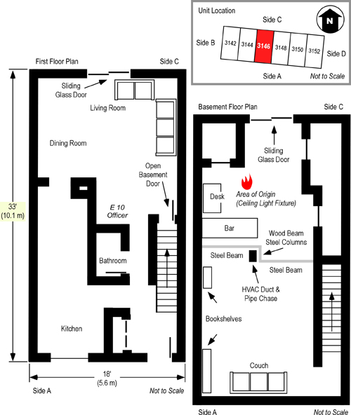
The fire originated in an electrical junction box attached to a fluorescent light fixture in the basement ceiling (see Figures 1 and 2). The occupants of the unit were awakened by a smoke detector. The female occupant noticed smoke coming from the floor vents on Floor 2. She proceeded downstairs and opened the front door and then proceeded down the first floor hallway towards Side C, but encountered thick smoke and high temperature. The female and male occupants exited the structure, leaving the front door open, and made contact with the occupant of an adjacent unit who notified the DC Fire & EMS Department at 0017 hours.

Dispatch Information

At 00:17, DC Fire & EMS Communications Division dispatched a first alarm assignment consisting of Engines 26, 17, 10, 12, Trucks 15, 4, Rescue Squad 1, and Battalion 1 to 3150 Cherry Road NE. At 0019 Communications received a second call, reporting a fire in the basement of 3146 Cherry Road NE. Communications transmitted the update with the change of address and report of smoke coming from the basement. However, only one of the responding companies (Engine 26) acknowledged the updated information.

Weather Conditions

Temperature was approximately 66o F (19o C) with south to southwest winds at 5-10 mi/hr (8-16 km/h), mostly clear with no precipitation.

Conditions on Arrival

Approaching the incident, Engine 26 observed smoke blowing across Bladensburg Road. Engine 26 arrived at a hydrant at the corner of Banneker Drive and Cherry Road at 00:22 hours and reported smoke showing. A short time later, Engine 26 provided an updated size-up with heavy smoke showing from Side A of a two story row house. Based on this report, Battalion 1 ordered a working fire dispatch and a special call for the Hazmat Unit at 00:23. This added Engine 14, Battalion 2, Medic 17 and EMS Supervisor, Air Unit, Duty Safety Officer, and Hazmat Unit.

Firefighting Operations

DC Fire and EMS Department standard operating procedures (SOP) specify apparatus placement and company assignments based on dispatch (anticipated arrival) order. Note that dispatch order (i.e., first due, second due) may de different than order of arrival if companies are delayed by traffic or are out of quarters.

Standard Operating Procedures

Operations from Side A

The first due engine lays a supply line to Side A, and in the case of basement fires, the first line is positioned to protect companies performing primary search on upper floors by placing a line to cover the interior stairway to the basement. The first due engine is backed up by the third due engine. The apparatus operator of the third due engine takes over the hydrant and pumps supply line(s) laid by the first due engine, while the crew advances a backup line to support protection of interior exposures and fire attack from Side A.

The first due truck takes a position on Side A and is responsible for utility control and placement of ladders for access, egress, and rescue on Side A. If not needed for rescue, the aerial is raised to the roof to provide access for ventilation.

The rescue squad positions on Side A (unless otherwise ordered by Command) and is assigned to primary search using two teams of two. One team searches the fire floor, the other searches above the fire floor. The apparatus operator assists by performing forcible entry, exterior ventilation, monitoring search progress, and providing emergency medical care as necessary.

Operations from Side C

The second due engine lays a supply line to the rear of the building (Side C), and in the case of basement fires, is assigned to fire attack if exterior access to the basement is available and if it is determined that the first and third due engines are in a tenable position on Floor 1. The second due engine is responsible for checking conditions in the basement, control of utilities (on Side C), and notifying Command of conditions on Side C. Command must verify that the first and third due engines can maintain tenable positions before directing the second due engine to attack basement fires from the exterior access on Side C.

The second due truck takes a position on Side C and is responsible for placement of ladders for access, egress, and rescue on Side C. The aerial is raised to the roof to provide secondary access for ventilation (unless other tasks take priority).

Command and Control

The battalion chief positions to have an unobstructed view of the incident (if possible) and uses his vehicle as the command post. On greater alarms, the command post is moved to the field command unit.

Notes: This summary of DC Fire & EMS standard operating procedures for structure fires is based on information provided in the reconstruction report and reflects procedures in place at the time of the incident. DC Fire & EMS did not use alpha designations for the sides of a building at the time of this incident. However, this approach is used here (and throughout the case) to provide consistency in terminology.

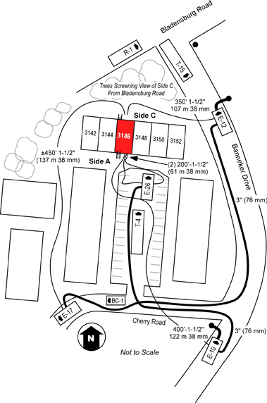
First due, Engine 26 laid a 3″ (76 mm) supply line from a hydrant at the intersection of Banneker Drive and Cherry Road NE, positioned in the parking lot on Side A, and advanced a 200′ 1-1/2″ ( 61 m 38 mm) pre-connected hoseline to the first floor doorway of the fire unit on Side A (see Figures 1 and 2). A bi-directional air track was evident at the door on Floor 1, Side A , with thick (optically dense) black smoke from the upper area of the open doorway. Engine 26’s entry was delayed due to a breathing apparatus facepiece malfunction. The crew of Engine 26 (Firefighters Mathews and Morgan and the Engine 26 Officer) made at approximately 00:24.

Figure 1. Plot and Floor Plan-3146 Cherry Road NE

plot_and_floor

Note: Adapted from Report from the Reconstruction Committee: Fire at 3146 Cherry Road NE, Washington DC, May 30, 1999, p. 18 & 20. District of Columbia Fire & EMS, 2000; Simulation of the Dynamics of the Fire at 3146 Cherry Road NE, Washington D.C., May 30, 1999, p. 12-13, by Daniel Madrzykowski & Robert Vettori, 2000. Gaithersburg, MD: National Institute of Standards and Technology, and NIOSH Death in the Line of Duty Report 99 F-21, 1999, p. 19.

Engine 10, the third due engine arrived shortly after Engine 26, took the hydrant at the intersection of Banneker Drive and Cherry Road, NE, and pumped Engine 26’s supply line. After Engine 10 arrived at the hydrant, the firefighter from Engine 26 who had remained at the hydrant proceeded to the fire unit and rejoined his crew. Engine 10, advanced a 400′ 1-1/2″ (122 m 38 mm) line from their own apparatus as a backup line. Firefighter Phillips and the Engine 10 officer entered through the door on Floor 1, Side A (see Figure 2) while the other member of their crew remained at the door to assist in advancing the line.

Truck 15, the first due truck arrived at 00:23 and positioned on Side A in the parking lot behind Engine 26. The crew of Truck 15 began laddering Floor 2, Side A, and removed kitchen window on Floor 1, Side A (see Figure 2). Due to security bars on the window, one member of Truck 15 entered the building and removed glass from the window from the interior. After establishing horizontal ventilation, Truck 15 accessed the roof via a portable ladder and began vertical ventilation operations.

Engine 17, the second due engine, arrived at 00:24, laid a 3″ (76 mm) supply line from the intersection of Banneker Drive and Cherry Road NE, to a position on Cherry Road NE just past the parking lot, and in accordance with department procedure, stretched a 350′ 1-1/2″ (107 m 38 mm) line to Side C (see Figure 2).

Approaching Cherry Road from Banneker Drive, Battalion 1 observed a small amount of fire showing in the basement and assigned Truck 4 to Side C. Battalion 1 parked on Cherry Road at the entrance to the parking lot, but was unable to see the building, and proceeded to Side A and assumed a mobile command position.

Second due, Truck 4 proceeded to Side C and observed what appeared to be a number of small fires in the basement at floor level (this was actually flaming pieces of ceiling tile which had dropped to the floor). The officer of Truck 4 did not provide a size-up report to Command regarding conditions on Side C. Truck 4, removed the security bars from the basement sliding glass door using a gasoline powered rotary saw and sledgehammer. After clearing the security grate Truck 4, broke the right side of the sliding glass door to ventilate and access the basement (at approximately 00:27) and then removed the left side of the sliding glass door. The basement door on Side C was opened prior to Engine 17 getting a hoseline in place and charged. After opening the sliding glass door in the basement, Truck 4 attempted to ventilate windows on Floor 2 Side C using the tip of a ladder. They did not hear the glass break and believing that they had been unsuccessful; they left the ladder in place at one of the second floor windows and continued with other tasks.

Figure 2. Location of First Alarm Companies and Hoselines

app_position

Note: Adapted from Report from the Reconstruction Committee: Fire at 3146 Cherry Road NE, Washington DC, May 30, 1999, p. 27. District of Columbia Fire & EMS, 2000.

Unknown to Truck 4, these windows had been left open by the exiting occupants. Truck 4B (two person team from Truck 4) returned to their apparatus for a ladder to access the roof from Side C. Rescue 1 arrived at 00:26 and reported to Side C after being advised by the male occupant that everyone was out of the involved unit (this information was not reported to Command). Rescue 1 and Truck 4 observed inward air track (smoke and air) at the exterior basement doorway on Side C and an increase in the size of the flames from burning material on the floor.

Engines 26 and 10 encountered thick smoke and moderate temperature as they advanced their charged 1-1/2″ (38 mm) hoselines from the door on Side A towards Side C in an attempt to locate the fire. As they extended their hoselines into the living room, the temperature was high, but tolerable and the floor felt solid. It is important to note that engineered, lightweight floor support systems such as parallel chord wood trusses do not provide reliable warning of impending failure (e.g., sponginess, sagging), failure is often sudden and catastrophic (NIOSH, 2005; UL, 2009).

Prior to reaching Side C of the involved unit, Engine 17 found that their 350′ 1-1/2″ (107 m 38 mm) hoseline was of insufficient length and needed to extend the line with additional hose.

Engine 12, the fourth arriving engine, picked up Engine 17’s line, completed the hoselay to a hydrant on Banneker Drive (see Figure 2). The crew of Engine 12 then advanced a 200′ 1-1/2″ (61 m 38 mm) hoseline from Engine 26 through the front door of the involved unit on Side A and held in position approximately 3′ (1 m) inside the doorway. This tactical action was contrary to department procedure, as the fourth due engine has a standing assignment to stretch a backup line to Side C.

Rescue 1’s B Team (Rescue 1B) and a firefighter from Truck 4 entered the basement without a hoseline in an effort to conduct primary search and access the upper floors via the interior stairway. Engine 17 reported that the fire was small and requested that Engine 17 apparatus charge their line.

Questions

Consider the following questions related to the interrelationship between strategies, tactics, and fire behavior:

  1. Based on the information provided to this point, what was the stage of fire development and burning regime in the basement when Engine 26 entered through the door on Floor 1, Side A? What leads you to this conclusion?
  2. What impact do you believe Truck 4’s actions to open the Basement door on Side C will have on the fire burning in the basement? Why?
  3. What is indicated by the strong inward flow of air after the Basement door on Side C is opened? How will this change in ventilation profile impact on air track within the structure?
  4. Did the companies at this incident operate consistently with DC Fire & EMS SOP? If not, how might this have influenced the effectiveness of operations?
  5. Committing companies with hoselines to the first floor when a fire is located in the basement may be able to protect crews conducting search (as outlined in the DC Fire & EMS SOP). However, what building factors increased the level of risk of this practice in this incident?

More to Follow

My next post will examine the extreme fire behavior phenomena that trapped Firefighters Phillips, Mathews, and Morgan and efforts to rescue them.

Master Your Craft

Remember the Past

This week marked the anniversary of the largest loss of life in a line-of-duty death incident in the history of the American fire service. Each September, we stop and remember the sacrifice made by those 343 firefighters. However, it is also important to remember and learn from events that take the lives of individual firefighters. In an effort to encourage us to remember the lessons of the past and continue our study of fire behavior, each month I include brief narratives and links to NIOSH Death in the Line of Duty reports and other documentation in my posts.

September 9, 2006
Acting CAPT Vincent R. Neglia
North Hudson Regional Fire & Rescue Department, NJ

Captain Neglia and other firefighters were dispatched to a report of fire in a three-story apartment building in Union City. Upon their arrival at the scene, firefighters found light smoke and no visible fire. Based on reports that the structure had not been evacuated, Captain Neglia and other firefighters entered the building to perform a search. Due to the light smoke conditions, Captain Neglia was not wearing his facepiece.

Captain Neglia was the first firefighter to enter an apartment. Conditions deteriorated rapidly as fire in the cockloft broke through a ceiling . Captain Neglia was trapped by rapid fire progress and subsequent collapse. Other firefighters came to his aid and removed him from the building. Captain Neglia was transported to the hospital but later died of a combination of smoke inhalation and burns.

NIOSH did not investigate and prepare a report on the incident that took the life of Captain Neglia.

Ed Hartin, MS, EFO, MIFireE, CFO

References

District of Columbia (DC) Fire & EMS. (2000). Report from the reconstruction committee: Fire at 3146 Cherry Road NE, Washington DC, May 30, 1999. Washington, DC: Author.

Madrzykowski, D. & Vettori, R. (2000). Simulation of the Dynamics of the Fire at 3146 Cherry Road NE Washington D.C., May 30, 1999, NISTR 6510. August 31, 2009 from http://fire.nist.gov/CDPUBS/NISTIR_6510/6510c.pdf

National Institute for Occupational Safety and Health (NIOSH). (1999). Death in the line of duty, Report 99-21. Retrieved August 31, 2009 from http://www.cdc.gov/niosh/fire/reports/face9921.html

National Institute for Occupational Safety and Health (NIOSH). (2005). NIOSH Alert: Preventing Injuries and Deaths of Fire Fighters Due to Truss System Failures. Retrieved August 31, 2009 from http://www.cdc.gov/niosh/fire/reports/face9921.html

Fire Behavior Case Study
Townhouse Fire: Washington, DC

Monday, September 7th, 2009

This series of posts focused on Understanding Flashover has provided a definition of flashover; examined flashover in the context of fire development in both fuel and ventilation controlled fires; and looked at the importance of air track on rapid fire progression through multiple compartments. To review prior posts see:

This post begins study of an incident that resulted in two line-of-duty deaths as a result of extreme fire behavior in a townhouse style apartment building in Washington, DC. This case study provides an excellent learning opportunity as it was one of the first times that the National Institute of Standards and Technology (NIST) Fire Dynamics Simulator (FDS) and Smokeview were used in forensic fire scene reconstruction to investigate fire dynamics involved in a line-of-duty death. Data development of this case study was obtained from Death in the line of duty, Report 99-21 (NIOSH, 1999), Report from the reconstruction committee: Fire at 3146 Cherry Road NE, Washington DC, May 30, 1999 (District of Columbia (DC Fire & EMS, 2000), and Simulation of the Dynamics of the Fire at 3146 Cherry Road NE Washington D.C., May 30, 1999 (Madrzykowski & Vettori, 2000).

The Case

In 1999, two firefighters in Washington, DC died and two others were severely injured as a result of being trapped and injured by rapid fire progress. The fire occurred in the basement of a two-story, middle of building, townhouse apartment with a daylight basement (two stories on Side A, three stories on Side C).

Figure 1. Cross Section of 3146 Cherry Road NE

cherry_road_cross_section

The first arriving crews entered Floor 1 from Side A to search for the location of the fire. Another crew approached from the rear and made entry to the basement through a patio door on Side C. Due to some confusion about the configuration of the building and Command’s belief that the crews were operating on the same level, the crew at the rear was directed not to attack the fire. During fireground operations, the fire in the basement intensified and rapidly extended to the first floor via the open, interior stairway.

Building Information

The unit involved in this incident was a middle of row 18′ x 33′ (5.6 m x 10.1 m) two-story townhouse with a daylight basement (see Figures 1 and 3). The building was of wood frame construction with brick veneer exterior and non-combustible masonry firewalls separating six individual dwelling units. Floors were supported by lightweight, parallel chord wood trusses. This type of engineered floor support system provides substantial strength, but has been demonstrated to fail quickly under fire conditions (NIOSH, 2005). In addition, the design of this type of engineered system results in a substantial interstitial void space between the ceiling and floor as illustrated in Figure 2.

Figure 2. Parallel Chord Truss Construction

paralell_chord_truss

Note: This is not an illustration of the floor assembly in the Cherry Road Townhouse. It is provided to illustrate the characteristics of wood, parallel chord truss construction.

The trusses ran from the walls on Sides A and C and were supported by steel beams and columns at the center of the unit (See Figure 3). The basement ceiling consisted of wood fiber ceiling tiles on wood furring strips which were attached to the bottom chord of the floor trusses. Basement walls were covered with gypsum board (sheetrock) and the floor was carpeted. A double glazed sliding glass door protected by metal security bars was located on Side C of the basement, providing access from the exterior. Side C of the structure (see Figure 3) was enclosed by a six-foot wood and masonry fence. The finished basement was used as a family room and was furnished with a mix of upholstered and wood furniture.

The first floor of the townhouse was divided into the living room, dining room, and kitchen. The basement was accessed from the interior via a stairway leading from the living room to the basement. The door to this stairway was open at the time of the fire (see Figures 1 and 3). The walls and ceilings on the first floor were covered with gypsum board (sheetrock) and the floor was carpeted. Contents of the first floor were typical of a residential living room and kitchen. A double glazed sliding glass door protected by metal security bars similar to that in the basement was located on Side C of the first floor. An entry door and double glazed kitchen window were located on Side A (see Figure 3). A stairway led to the second floor from the front entry. The second floor contained bedrooms (but was not substantively involved in this incident). There were double glazed windows on Sides A and C of Floor 2.

Figure 3. Plot and Floor Plan-3146 Cherry Road NE

plot_and_floor

Note: Adapted from Report from the Reconstruction Committee: Fire at 3146 Cherry Road NE, Washington DC, May 30, 1999, p. 18 & 20. District of Columbia Fire & EMS, 2000; Simulation of the Dynamics of the Fire at 3146 Cherry Road NE, Washington D.C., May 30, 1999, p. 12-13, by Daniel Madrzykowski & Robert Vettori, 2000. Gaithersburg, MD: National Institute of Standards and Technology, and NIOSH Death in the Line of Duty Report 99 F-21, 1999, p. 19.

Figure 4. Side A 3146 Cherry Road NE

side_a_post_fire

Note: Adapted from Report from the Reconstruction Committee: Fire at 3146 Cherry Road NE, Washington DC, May 30, 1999, p. 17. District of Columbia Fire & EMS, 2000 and Simulation of the Dynamics of the Fire at 3146 Cherry Road NE, Washington D.C., May 30, 1999, p. 5, by Daniel Madrzykowski & Robert Vettori, 2000. Gaithersburg, MD: National Institute of Standards and Technology.

Figure5. Side C 3146 Cherry Road NE

side_c_post_fire

Note: Adapted from Report from the Reconstruction Committee: Fire at 3146 Cherry Road NE, Washington DC, May 30, 1999, p. 19. District of Columbia Fire & EMS, 2000 and Simulation of the Dynamics of the Fire at 3146 Cherry Road NE, Washington D.C., May 30, 1999, p. 5, by Daniel Madrzykowski & Robert Vettori, 2000. Gaithersburg, MD: National Institute of Standards and Technology.

The Fire

The fire originated in an electrical junction box attached to a fluorescent light fixture in the basement ceiling (see Figures 1 and 3). The occupants of the unit were awakened by a smoke detector. The female occupant noticed smoke coming from the floor vents on Floor 2. She proceeded downstairs and opened the front door and then proceeded down the first floor hallway towards Side C, but encountered thick smoke and high temperature. The female and male occupants exited the structure, leaving the front door open, and made contact with the occupant of an adjacent unit who notified the DC Fire & EMS Department at 0017 hours.

Questions

It is important to remember that consideration of how a fire may develop and the relationship between fire behavior and your strategies and tactical operations must begin prior to the time of alarm. Assessment of building factors and fire behavior prediction should be integrated with pre-planning.

  1. Based on the information provided about the fire and building conditions, how would you anticipate that this fire would develop?
  2. What concerns would you have if you were the first arriving company at this incident?

More to Follow

My next post will examine dispatch information and initial tactical operations by first alarm companies.

Master Your Craft

Ed Hartin, MS, EFO, MIFireE, CFO

References

District of Columbia (DC) Fire & EMS. (2000). Report from the reconstruction committee: Fire at 3146 Cherry Road NE, Washington DC, May 30, 1999. Washington, DC: Author.

Madrzykowski, D. & Vettori, R. (2000). Simulation of the Dynamics of the Fire at 3146 Cherry Road NE Washington D.C., May 30, 1999, NISTR 6510. August 31, 2009 from http://fire.nist.gov/CDPUBS/NISTIR_6510/6510c.pdf

National Institute for Occupational Safety and Health (NIOSH). (1999). Death in the line of duty, Report 99-21. Retrieved August 31, 2009 from http://www.cdc.gov/niosh/fire/reports/face9921.html

National Institute for Occupational Safety and Health (NIOSH). (2005). NIOSH Alert: Preventing Injuries and Deaths of Fire Fighters Due to Truss System Failures. Retrieved August 31, 2009 from http://www.cdc.gov/niosh/fire/reports/face9921.html

Understanding Flashover:
The Importance of Air Track

Monday, August 31st, 2009

This is the fourth in a series of posts dealing with flashover, to review prior posts see:

As previously discussed flashover requires sufficient heat release rate for the temperature of fuel packages within a compartment to increase sufficiently to ignite and the fire to rapidly transition to the fully developed stage. However, during fire development in a compartment the fire often becomes ventilation controlled, with fire growth and heat release rate limited by the available air supply. In some cases, the fire generates sufficient heat release rate despite being ventilation controlled. In others, there is insufficient oxygen in the air supplied for the fire to reach flashover (unless ventilation is increased). All of this is fairly simple and straightforward if we are examining fire in a single compartment. This simple explanation of flashover is based on fire development in a single compartment, such as that described in the ISO 9705 Fire Tests-Full Scale Room Fire Tests for Surface Products6American Society for Testing and Materials (ASTM) Standard E 603-6 (Figure 1)

Figure 1. Full Scale (Six Sided) Room Fire Test Compartment

ul_compartment_fire

Note: Underwriters Laboratory (UL) fire test photo adapted from Fire Behavior in Single Family Dwellings, [PowerPoint Presentation], National Fire Academy.

Things get a bit more complex when a fire occurs in a multi-compartment building as individual compartments are interconnected smoke and flames may extend from compartment to compartment throughout the building.

Ventilation and Air Track

Contrary to the common fire service definition of ventilation as “[planned and] systematic removal of heated air, smoke, and fire gases and replacing them with cooler air (IFSTA, 2008), ventilation is simply the exchange of the atmosphere inside the building with that which is outside. This process is ongoing under normal, non-fire conditions. However, under fire conditions, ventilation also involves movement of smoke and air between compartments as well as discharge of smoke from the building and intake of air from outside the structure.

Remember! If you can see smoke coming from the building, ventilation is occurring (but not necessarily the type or amount of ventilation that you need to effectively control the fire environment and the fire).

The term air track is used to describe the characteristics of air and smoke movement (e.g., direction, velocity). The movement of both air and smoke are important, but the direction and path of smoke movement is particularly significant for several reasons:

  • Smoke is fuel
  • Hot smoke has energy

Through convection, smoke carries energy away from the fire compartment and transfers this energy to objects having lower temperature (such as other fuel packages or firefighters working inside the building). The rate of heat transfer is substantially dependent on temperature difference and in the case of convection on the velocity of the hot gases. Higher velocity and turbulence results in a higher rate of convective heat transfer (much the same as the increase in wind chill as wind speed increases in a cold environment).

Air Track on a Single Level

Examination of air track on a single level provides a simple way to illustrate the influence of air track on the movement of smoke (think fuel and energy) from compartment to compartment, fire extension, and multi-compartment flashover.

With no significant ventilation (with the exception of slight building leakage) smoke will fill the fire compartment and extend through openings such as doorways to adjacent compartments (see Figure 2). If insufficient oxygen is available from the air within the compartments the fire will become ventilation controlled and growth may slow and the fire may decay (heat release rate lessens)

Figure 2. Limited Ventilation

single_level_no_vent

Note: Unless the building is tightly sealed, there is likely to be some leakage resulting in smoke discharge and inward movement of air.

If an opening is made in the presently uninvolved compartment, smoke will move from the fire to the opening, exiting out the upper area of the opening while cool air moves inward through the bottom of the opening and towards the fire (see Figure 3). This is a bi-directional air track.

Figure 3: Single Opening with Bi-Directional Air Track

single_level_one_vent

As pointed out in The Myth of the Self-Vented Fire and The Ventilation Paradox, providing additional oxygen to a ventilation controlled fire results in increased heat release rate and may result in ventilation induced flashover. However, it is important to consider how this impacts adjacent compartments as well.

Increased heat release rate in a still ventilation controlled fire results in higher hot gas layer temperatures and increased smoke production. Increasing temperature and volume of the hot gas layer will cause it to lower and velocity to increase as the smoke moves through adjacent compartments and out ventilation openings. This increases both radiant and convective heat transfer and potentially speeds progression to flashover in adjacent compartments.

Horizontal tactical ventilation can be accomplished rapidly and may, under some conditions, be a useful approach to improving interior conditions. Increasing the number and size of horizontal openings can raise the level of the hot gas layer (by providing additional exhaust). However, when dealing with a ventilation controlled fire the increased oxygen supplied to the fire will increase heat release rate. In addition, in the absence of wind or application of positive pressure at the entry point, two openings at the same level will result in a bi-directional air track at both openings as illustrated in Figure 4.

Figure 4. Two Openings with a Bi-Directional Air Track

single_level_two_vents

If heat release rate is sufficient, this may result in vent induced flashover in the compartments between the fire and the exhaust openings as illustrated in the following video clip.

Important! Horizontal ventilation is not a bad tactic. However, it is essential to recognize and manage the air track as well as ensuring that ventilation is coordinated with fire attack.

More to Follow

Examination of the flashover phenomenon will continue with a case study involving a 1999 fire in a Washington, DC townhouse that resulted in the line of duty deaths of two firefighters. This incident is particularly important as it is one of the first times that the National Institute of Standards and Technology (NIST) Fire Dynamics Simulator (FDS) and Smokeview were used for forensic fire scene reconstruction. This data, in conjunction with the District of Columbia Fire and EMS Reconstruction Report and National Institute for Occupational Safety and Health (NIOSH) Death in the Line of Duty Report provides a solid basis for understanding the impact of burning regime and air track in multi-compartment, ventilation induced flashover.

Ed Hartin, MS, EFO, MIFireE, CFO

References

International Fire Service Training Association (IFSTA). (2008). Essentials of firefighting (5th ed.). Stillwater, OK: Fire Protection Publications.

Reading the Fire:
Heat Indicators Part 2

Thursday, August 20th, 2009

Reading the Fire Heat Indicators briefly examined energy, temperature, and heat in thermodynamic systems, and introduced the two major categories of heat related fire behavior indicators: those that we can see (visual) and others that can be felt (tactile) as illustrated in Figure 1.

Figure 1. Basic Heat Indicator Categories

heat_indicators_5-2-2

As with each of the B-SAHF (building, smoke, air track, heat, and flame) indicators, it is essential that assessment of heat is integrated with other elements of the B-SAHF scheme to gain a clearer sense of fire conditions and likely fire behavior.

The Thermal Environment

The thermal environment that firefighters encounter can be complex, but involves one or more of the following scenarios (Bryner, Madrzykowski, & Stroup, 2005):

  • Immersion in a relatively static layer of hot gases (i.e., crawling or crouching in a room full of hot combustion products and smoke)
  • Contact with a moving layer of hot gases (i.e., entry through a door or moving down a hallway with a strong air track)
  • Exposure to radiant heat (i.e., working in proximity to flames or below a layer of hot gases)

Figure 2 illustrates the variations in temperature that firefighters may encounter during operations in a highly compartmentalized, multi-level structure. It is important to note that temperature varies from compartment to compartment and at different levels within each compartment.

Figure 2. Smokeview Slice

smokeview_temp_slice

Note: Adapted from National Institute of Standards and Technology (NIST) Visualization techniques, Slice animation of a townhouse kitchen fire.

Firefighters’ personal protective equipment insulates them from the thermal environment. This layer of insulation makes it difficult to accurately assess temperature and heat flux (amount of heat transfer) that they are exposed to during firefighting operations. The thermal insulation provided by personal protective equipment slows, but does not stop heat transfer from the fire environment to the firefighter. Thermal exposure is dependent on gas temperature and radiant heat flux (heat transfer due to radiation)./

Thermal exposure can be divided into four categories: Ordinary, Hazardous, Extreme, and Critical (Foster & Roberts, 1995; Donnelly, Davis, Lawson, J., Selpak, 2006). As illustrated in Figure 3.

Figure 3. Thermal Exposure Limits in the Firefighting Environment

thermal_environment

Note: Adapted from Measurements of the firefighting environment. Central Fire Brigades Advisory Council Research Report 61/1994 by J.A. Foster & G.V. Roberts, 1995. London: Department for Communities and Local Government and Thermal Environment for Electronic Equipment Used by First Responders by M.K. Donnelly, W.D. Davis, J.R. Lawson, & M.J. Selepak, 2006, Gaithersburg, MD: National Institute of Standards and Technology.

Several challenges confront firefighters in assessing the thermal environment during firefighting operations. These include:

  • Of necessity, firefighters are insulated from their environment, delaying tactile perception of changes in temperature and heat flux.
  • Perception of temperature is influenced by a wide range of factors and varies considerably from individual to individual.
  • Firefighters focused on the task at hand may not notice subtle changes in temperature and heat flux.
  • Temperature and heat flux do not always present obvious visual indicators.
  • Conditions can change extremely rapidly, particularly as the fire approaches flashover.
  • Firefighters may ignore warning signs of worsening conditions, believing that it is part of the job to tolerate extreme conditions.

Firefighters must have a sound understanding of the thermal environment encountered during firefighting operations and the, at times, subtle indicators of changing thermal conditions.

Tactile Effects

Tactile effects include sensing temperature or temperature change. Firefighters may sense temperature and changes in temperature, but as noted earlier, this is limited by the extent of thermal protection provided by their protective clothing and focus on the task at hand. Firefighters’ protective clothing effectively insulates them from the thermal hazards typically encountered in firefighting. The multiple layers of insulation in the protective ensemble slows (but does not stop) heat transfer. This time lag makes it difficult for the firefighter to appreciate their thermal exposure (Bryner, Madrzykowski, & Stroup, 2005).

Firefighter’s personal alert safety system (PASS) devices may be equipped with a temperature sensing function that provides warning at a specified exposure value when the specified temperature is exceeded for a specified time period (Figure 4). However, National Fire Protection Association 1982 Standard on Personal Alert Safety Systems (PASS) (NFPA, 2007) does not address thermal sensing and there is not standardized test protocol for these types of devices (Bryner, Madrzykowski, & Stroup, 2005). Thermal sensing devices use a temperature response curve to provide warning for long duration exposure to lower temperature and short duration exposure to higher temperature. However, during rapid increases in temperature such as those encountered in flashover or other forms of rapid fire development, adequate early warning to permit egress is unlikely due to limited sensitivity of the sensors (Bryner, Madrzykowski, & Stroup, 2005). While firefighters must be attentive to heat level and temperature change, it is often difficult to perceive these changes quickly enough to react to rapidly developing fire conditions. This reinforces the importance of integrating all the fire behavior indicators in your ongoing size-up and dynamic risk assessment.

Figure 4. PASS Device Temperature Sensor

pass_temp_curve

Next Steps

The next post will conclude this look at Heat Indicators with examination of visual effects. While temperature and heat transfer cannot be observed directly, there are a number of ways in which firefighters can see the effects of temperature and heat.

Ed Hartin, MS, EFO, MIFireE, CFO

References

Bryner, N., Madrzykowski, D., Stroup, D. (2005). Performance of thermal exposure sensors in personal alert safety system (PASS) devices, NISTR 7294. Retrieved August 19, 2009 from http://www.fire.nist.gov/bfrlpubs/NIST_IR_7294.pdf.

Donnelly, M., Davis, W., Lawson, J., & Selpak, M. (2006). Thermal environment for electronic equipment used by first responders, NIST Technical Note 1474. Retrieved August 19, 2009 from http://www.fire.nist.gov/bfrlpubs/fire06/PDF/f06001.pdf

National Institute of Standards and Technology (NIST) Visualization techniques, Slice animation of a townhouse kitchen fire, [digital video file]. Retrieved August 19, 2009 from http://www.fire.nist.gov/fds4/refs/thouse3/thouse3_slice.avi