Posts Tagged ‘fire behavior indicators’

Influence of Ventilation in Residential Structures: Tactical Implications Part 5

Thursday, September 8th, 2011

The fifth tactical implication identified in the Underwriters Laboratories study of the Impact of Ventilation on Fire Behavior in Legacy and Contemporary Residential Construction (Kerber, 2011) is described as failure of the smoke layer to lift following horizontal natural ventilation and smoke tunneling and rapid air movement in through the front door.

In the experiments conducted by UL, both the single and two story dwellings filled rapidly with smoke with the smoke layer reaching the floor prior to ventilation. This resulted in zero visibility throughout the interior (with the exception of the one bedroom with a closed door). After ventilation, the smoke layer did not lift (as many firefighters might anticipate) as the rapid inward movement of air simply produced a tunnel of clear space just inside the doorway.

Put in the context of the Building, Smoke, Air Track, Heat, and Flame (B-SAHF) fire behavior indicators, these phenomena fit in the categories of smoke and air track. Why did these phenomena occur and what can firefighters infer based on observation of these fire behavior indicators?

Smoke Versus Air Track

There are a number of interrelationships between Smoke and Air Track. However, in the B-SAHF organizing scheme they are considered separately. As we begin to develop or refine the map of Smoke Indicators it is useful to revisit the difference between these two categories in the B-SAHF scheme.

Smoke: What does the smoke look like and where is it coming from? This indicator can be extremely useful in determining the location and extent of the fire. Smoke indicators may be visible on the exterior as well as inside the building. Don’t forget that size-up and dynamic risk assessment must continue after you have made entry!

Air Track: Related to smoke, air track is the movement of both smoke (generally out from the fire area) and air (generally in towards the fire area). Observation of air track starts from the exterior but becomes more critical when making entry. What does the air track look like at the door? Air track continues to be significant when you are working on the interior.

Smoke Indicators

There are a number of smoke characteristics and observations that provide important indications of current and potential fire behavior. These include:

  • Location: Where can you see smoke (exterior and interior)?
  • Optical Density (Thickness): How dense is the smoke? Can you see through it? Does it appear to have texture like velvet (indicating high particulate content)?
  • Color: What color is the smoke? Don’t read too much into this, but consider color in context with the other indicators.
  • Physical Density (Buoyancy): Is the smoke rising, sinking, or staying at the same level?
  • Thickness of the Upper Layer: How thick is the upper layer (distance from the ceiling to the bottom of the hot gas layer)?

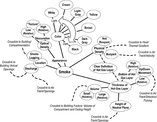
As discussed in Reading the Fire: Smoke Indicators Part 2, these indicators can be displayed in a concept map to show greater detail and their interrelationships (Figure 1).

Figure 1. Smoke Indicators Concept Map
Air Track

Air track includes factors related to the movement of smoke out of the compartment or building and the movement of air into the fire. Air track is caused by pressure differentials inside and outside the compartment and by gravity current (differences in density between the hot smoke and cooler air). Air track indicators include velocity, turbulence, direction, and movement of the hot gas layer.

  • Direction: What direction is the smoke and air moving at specific openings? Is it moving in, out, both directions (bi-directional), or is it pulsing in and out?
  • Wind: What is the wind direction and velocity? Wind is a critical indicator as it can mask other smoke and air track indicators as well as serving as a potentially hazardous influence on fire behavior (particularly when the fire is in a ventilation controlled burning regime).
  • Velocity & Flow: High velocity, turbulent smoke discharge is indicative of high temperature. However, it is essential to consider the size of the opening as velocity is determined by the area of the discharge opening and the pressure. Velocity of air is also an important indicator. Under ventilation controlled conditions, rapid intake of air will be followed by a significant increase in heat release rate.

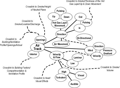
As discussed in Reading the Fire: Air Track Indicators Part 2, these indicators can be displayed in a concept map to show greater detail and their interrelationships (Figure 2).

Figure 2. Air Track Indicators Concept Map

air t
Discharge of smoke at openings and potential openings (Building Factors) is likely the most obvious indicator of air track while lack of smoke discharge may be a less obvious, but equally important sign of inward movement of air. Observation and interpretation of smoke and air movement at openings is an essential part of air track assessment, but it must not stop there. Movement of smoke and air on the interior can also provide important information regarding fire behavior.

An Ongoing Process

Reading the fire is an ongoing process, beginning with reading the buildings in your response area prior to the incident and continuing throughout firefighting operations. It is essential to not only recognize key indicators, but to also note changing conditions. This can be difficult when firefighters and officer are focused on the task at hand.

UL Experiment 13

This experiment examined the impact of horizontal ventilation through the door on Side A and one window as high as possible on Side C near the seat of the fire. The family room was the fire compartment. This room had a high (two-story) ceiling with windows at ground level and the second floor level (see Figure 3).

Figure 3. Two-Story Dwelling
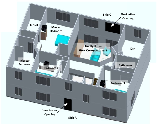
In this experiment, the fire was allowed to progress for 10:00 after ignition, at which point the front door (see Figure 3) was opened to simulate firefighters making entry. Fifteen seconds after the front door was opened (10:15), an upper window in the family room (see Figure 3) was opened. No suppression action was taken until 12:28, at which point a 10 second application of water was made through the window on Side C using a straight stream from a combination nozzle.

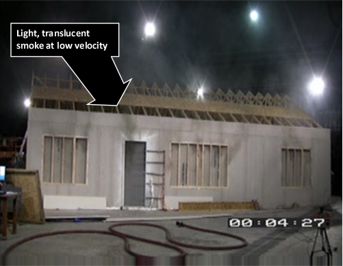
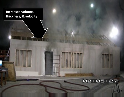
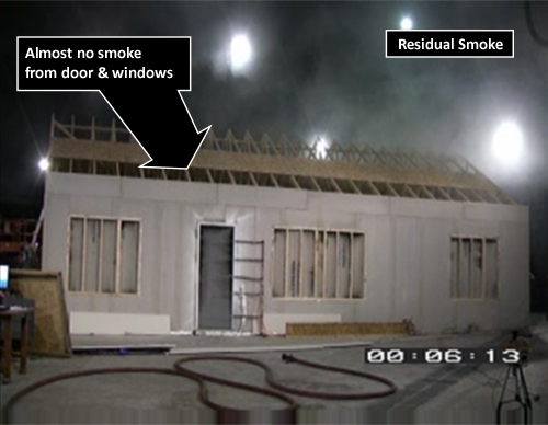
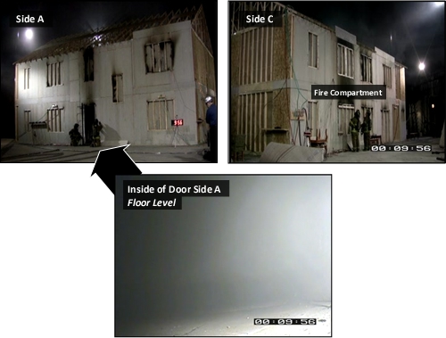
As with all the other experiments in this series fire development followed a consistent path. The fire quickly consumed much of the available oxygen inside the building and became ventilation controlled. At oxygen concentration was reduced, heat release rate and temperature within the building also dropped. Concurrently, smoke and air track indicators visible from the exterior were diminished. Just prior to opening the door on Side A, there was little visible smoke from the structure (see Figure 4).

Figure 4. Experiment 13 at 00:09:56 (Prior to Ventilation)
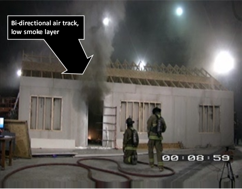
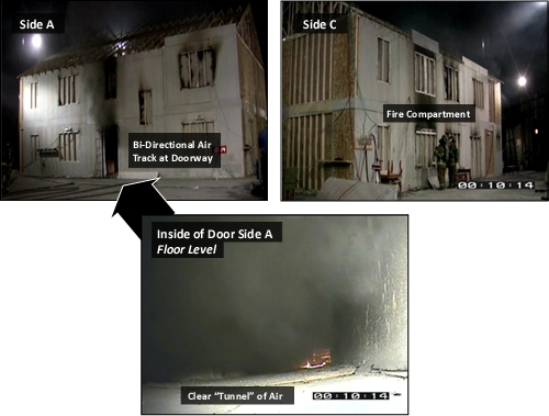
As illustrated in Figure 5, a bi-directional air track was created when the front door was opened. Hot smoke flowed out the upper area of the doorway while air pushed in the bottom creating a tunnel of clear space inside the doorway (but no generalized lifting of the upper layer.

Figure 5. Experiment 13 at 00:10:14 (Door Open)
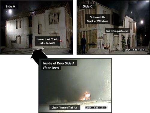
As illustrated in Figure 6, opening the upper level window in the family room resulted in a unidirectional air track flowing from the front door to the upper level window in the family room. No significant exhaust of smoke can be seen at the front door, while a large volume of smoke is exiting the window. However, while the tunneling effect at floor level was more pronounced (visibility extended from the front door to the family room), there was no generalized lifting of the upper layer throughout the remainder of the building.

Figure 6. Experiment 13 at 00:10:21 (Door and Window Open)
With the increased air flow provided by ventilation through the door on Side A and Window at the upper level on Side C, the fire quickly transitioned to a fully developed stage in the family room. The heat release rate (HRR) and smoke production quickly exceeded the limited ventilation provided by these two openings and the air track at the front door returned to bi-directional (smoke out at the upper level and air in at the lower level) as shown in Figure 7.

Figure 7. Experiment 13 at 00:11:22 (Door and Window Open)
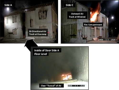
What is the significance of this observation? Movement of smoke out the door (likely the entry point for firefighters entering for fire attack, search, and other interior operations) points to significant potential for flame spread through the upper layer towards this opening. The temperature of the upper layer is hot, but flame temperature is even higher, increasing the radiant heat flux (transfer) to crews working below. Flame spread towards the entry point also has the potential to trap, and injure firefighters working inside.

Gas Velocity and Air Track

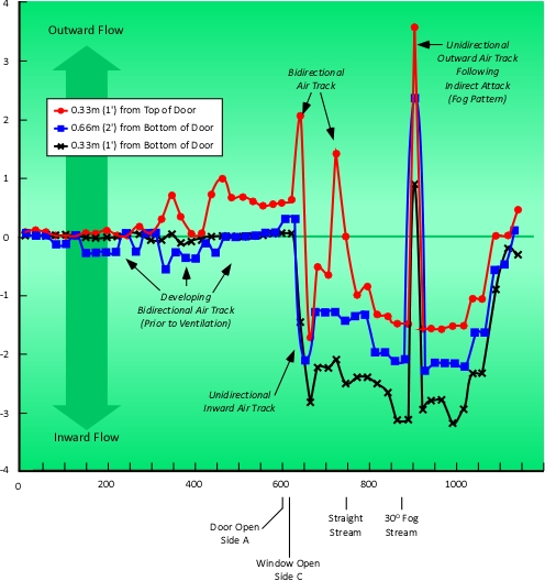
A great deal can be learned by examining both the visual indicators illustrated in Figures 4-7 and measurements taken of gas velocity at the front door. During the ventilation experiments conducted by UL, gas velocities were measured at the front door and at the window used for ventilation (see Figure 3). Five bidirectional probes were placed in the doorway at 0.33 m (1’) intervals. Positive values show gas movement out of the building while negative values show inward gas movement. In order to provide a simplified view of gas movement at the doorway, Figure 8 illustrates gas velocity 0.33 m (1’) below the top of the door, 0.33 m (1’) from the bottom of the door, and 0.66 m (2’) above the bottom of the door.

A bidirectional (out at the top and in at the bottom) air track developed at the doorway before the door was opened (see Figure 8) as a result of leakage at this opening. It is interesting to note variations in the velocity of inward movement of air from the exterior of the building, likely a result of changes in combustion as the fire became ventilation controlled. The outward flow at the upper level resulted in visible smoke on the exterior of the building. While not visible, inward movement of air was also occurring (as shown by measurement of gas velocity at lower levels in the doorway.

Creation of the initial ventilation opening by opening the front door created a strong bidirectional air track with smoke pushing out the top of the door while air rapidly moved in the bottom. Had the door remained the only ventilation opening, this bidirectional flow would have been sustained (as it was in all experiments where the door was the only ventilation opening).

Opening the upper window in the family room resulted in a unidirectional flow inward through the doorway. However, this phenomenon was short lived, with the bidirectional flow reoccurring in less than 60 seconds. This change in air track resulted from increased heat release rate as additional air supply was provided to the fire in the family room.

Figure 8. Front Door Velocities
Note: Adapted from Impact of Ventilation on Fire Behavior in Legacy and Contemporary Residential Construction (p. 243), by Stephen Kerber, Northbrook, IL: Underwriters Laboratories, 2011.

While not the central focus of the UL research, these experiments also examined the effects of exterior fire stream application on fire conditions and tenability. Each experiment included a 10 second application with a straight stream and a 10 second application of a 30o fog pattern. Between these two applications, fire growth was allowed to resume for approximately 60 seconds.

The straight stream application resulted in a reduction of temperature in the fire compartment and adjacent compartments (where there was an opening to the family room or hallway) as water applied through the upper window on Side C (ventilation opening) cooled the compartment linings (ceiling and opposite wall) and water deflected off the ceiling dropped onto the burning fuel. As the stream was applied, air track at the door on Side A changed from bidirectional to unidirectional (inward). This is likely due to the reduction of heat release rate achieved by application of water onto the burning fuel with limited steam production.

When the fog pattern was applied, there was also a reduction of temperature in the fire compartment and adjacent compartments (where there was an opening in the family room or hallway) as water was applied through the upper window on Side C (ventilation opening) cooled the upper layer, compartment linings, and water deflected off the ceiling dropped onto the burning fuel. The only interconnected area that showed a brief increase in temperature was the ceiling level in the dining room. However, lower levels in this room showed an appreciable drop in temperature. Air track at the door on Side A changed from bidirectional to unidirectional (outward) when the fog stream was applied. This effect is likely due to air movement inward at the window on Side C and the larger volume of steam produced on contact with compartment linings as a result of the larger surface area of the fog stream.

The effect of exterior streams will be examined in more detail in a subsequent post.

Important Lessons

The fifth tactical implication identified in the Underwriters Laboratories study of the Impact of Ventilation on Fire Behavior in Legacy and Contemporary Residential Construction (Kerber, 2011) is described as failure of the smoke layer to lift following horizontal natural ventilation and smoke tunneling and rapid air movement in through the front door.

Additional lessons that can be learned from this experiment include:

  • Ventilating horizontally at a high point results in higher flow of both air and smoke.
  • Increased inward air flow results in a rapid increase in heat release rate.
  • The rate of fire growth quickly outpaced the capability of the desired exhaust opening, returning the intended inlet to a bi-directional air track (potentially placing firefighters entering for fire attack or search at risk due to rapid fire spread towards their entry point).

Tactical applications of this information include:

  • Ensure that the attack team is in place with a charged line and ready to (or has already) attack the fire (not simply ready to enter the building) before initiating horizontal ventilation.
  • Cool the upper layer any time that it is above 100o C (212o F) to reduce radiant and convective heat flux and to limit potential for ignition and flaming combustion in the upper layer.

Note that this research project did not examine the impact of gas cooling, but examination of the temperatures at the upper levels in this experiment (and others in this series) point to the need to cool hot gases overhead.

What’s Next?

I am on the hunt for videos that will allow readers to apply the tactical implications of the UL study that have been examined to this point in conjunction with the B-SAHF fire behavior indicators. My next post will likely provide an expanded series of exercises in Reading the Fire.

The next tactical implication identified in the UL study (Kerber, 2011) examines the hazards encountered during Vent Enter Search (VES) tactical operations. A subsequent post will examine this tactic in some detail and explore this tactical implication in greater depth.

References

Kerber, S. (2011). Impact of ventilation on fire behavior in legacy and contemporary residential construction. Retrieved July 16, 2011 from http://www.ul.com/global/documents/offerings/industries/buildingmaterials/fireservice/ventilation/DHS%202008%20Grant%20Report%20Final.pdf

Reading the Fire 15

Sunday, July 24th, 2011

Developing and maintaining proficiency in reading the Fire using the B-SAHF (Building, Smoke, Air Track, Heat, and Flame) organizing scheme for fire behavior indicators, requires practice. This post provides an opportunity to exercise your skills using a video segment shot during a commercial fire.

Residential Fire

This post examines fire development during a residential fire in New Chicago, Indiana.

Download and the B-SAHF Worksheet.

Watch the first 30 seconds (0:30) of the video. First, describe what you observe in terms of the Building, Smoke, Air Track, Heat, and Flame Indicators; then answer the following five standard questions?

  1. What additional information would you like to have? How could you obtain it?
  2. What stage(s) of development is the fire likely to be in (incipient, growth, fully developed, or decay)?
  3. What burning regime is the fire in (fuel controlled or ventilation controlled)?
  4. What conditions would you expect to find inside this building?
  5. How would you expect the fire to develop over the next two to three minutes

In addition, consider how the answers to these questions impact your assessment of the potential for survival of possible occupants.

Now watch the video clip from 0:30 until firefighters make entry at 3:05. Now answer the following questions:

  1. Did fire conditions progress as you anticipated?
  2. What changes in the B-SAHF indicators did you observe?
  3. How do you think that the stage(s) of fire development and burning regime will change over the next few minutes?
  4. What conditions would you expect to find inside this building now?
  5. How would you expect the fire to develop over the next two to three minutes

The crews working in this video appeared to achieve fire control fairly quickly and without incident. However, consider the following tactical and task related questions:

  1. It did not appear that any member of the first arriving companies performed a 360o recon and size-up (they may have, but this was not visible in the video). Why might this be a critical step in size-up at a residential fire?
  2. It appeared that two lines were run simultaneously (the first line to the door ended up as the back-up line, possibly due to a slight delay in charging the line). How should fire attack and backup roles be coordinated?
  3. Fire attack was initiated from the interior (unburned side). What would have been the impact of the first line darkening the fire from the exterior (prior to entry)?
  4. Were there any indicators of potential collapse (partial) of the roof? How would you manage this risk when working in a lightweight wood frame residence with observed extension into the trussloft? What factors would influence your decision-making and actions?

Reading the Fire

See the following posts for more information on reading the fire:

Ed Hartin, MS, EFO, MIFireE, CFO

Influence of Ventilation in Residential Structures: Tactical Implications Part 3

Sunday, July 17th, 2011

UL’s third tactical implication is that there may be little smoke showing when a fire initially enters the decay stage as a result of limited ventilation. These fire conditions may present similar indicators to an incipient fire. However, fire conditions and the hazards presented to firefighters are considerably different.

Visible Indications of Fire Development

In Reading the Fire: B-SAHF, I introduced Building, Smoke, Air Track, Heat, and Flame (B-SAHF) as an organizing scheme for fire behavior indicators. Use of a standardized and organized approach to reading the fire can improve our ability to assess current fire conditions and predict likely fire development and changes that may occur.

Station Officer Shan Raffel of Queensland (Australia) Fire Rescue recently published an excellent article titled The Art of Reading Fire on the FirefighterNation website that provides another view of the B-SAHF indicators and Reading the Fire.

Building factors (particularly the normal ventilation profile, size and compartmentation, and thermal characteristics) can have a significant impact on fire development and how fire conditions present from the exterior of the building. However, this UL tactical implication relates most closely to Smoke and Air Track as well as somewhat indirectly to Heat (but this is the key to understanding what is happening). First a quick review of these key indicators

Smoke: What does the smoke look like and where is it coming from? This indicator can be extremely useful in determining the location and extent of the fire. Smoke indicators may be visible on the exterior as well as inside the building.

Air Track: Related to smoke, air track is the movement of both smoke (generally out from the fire area) and air (generally in towards the fire area).

Heat: This includes a number of indirect indicators. Heat cannot be observed directly, but you can feel changes in temperature and may observe the effects of heat on the building and its contents. Visual clues such as crazing of glass and visible pyrolysis from fuel that has not yet ignited are also useful heat related indicators. Important: Temperature influences smoke and air track indicators such as volume and velocity of smoke discharge.

For a more detailed look at B-SAHF and reading the fire, see the following posts:

How to Improve Your Skills
Building Factors
Building Factors Part 2
Building Factors Part 3
Smoke Indicators
Smoke Indicators Part 2
Air Track Indicators
Air Track Indicators Part 2
Heat Indicators
Heat Indicators Part 2
Heat Indicators Part 3
Flame Indicators
Flame Indicators Part 2
Incipient Stage Fires: Key Fire Behavior Indicators
Growth Stage Fires: Key Fire Behavior Indicators
Fully Developed Fires: Key Fire Behavior Indicators
Decay Stage Fires: Key Fire Behavior Indicators

Stages of Fire Development, Burning Regime, Smoke, Air Track & Heat

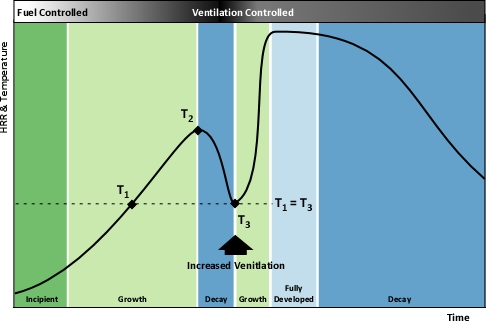
While the “stages of fire” have been described differently in fire service textbooks the phenomenon of fire development is the same. For our purposes, the stages of fire development in a compartment will be described as incipient, growth, fully developed and decay (see Figure 1). Despite dividing fire development into four “stages” the actual process is continuous with “stages” flowing from one to the next. While it may be possible to clearly define these transitions in the laboratory, in the field it is often difficult to tell when one ends and the next begins.

Understanding the stages of fire development is important, but this only provides a limited picture of fire development in a compartment. Conversion of chemical potential energy from fuel depends on availability of adequate oxygen for the combustion reaction to occur. As the ambient air in the compartment provides adequate oxygen, in incipient stage and early growth stage, heat release rate is limited by the chemical and physical characteristics of the fuel. This condition is known as a fuel controlled burning regime. In a compartment fire, combustion occurs in an enclosure where the air available for combustion is limited by 1) the volume of the compartment and 2) ventilation. Ventilation in a compartment fire is limited (particularly if doors and windows are closed and intact), as the fire grows and heat release rate increases, so too does demand for oxygen. When fire growth is limited by the available oxygen, heat release rate is slowed and then diminishes. This condition is known as a ventilation controlled burning regime.

Many if not most fires that have progressed beyond the incipient stage when the fire department arrives are ventilation controlled. This means that the heat release rate (the fire’s power) is limited by the existing ventilation. If ventilation is increased, either through tactical action or unplanned ventilation resulting from effects of the fire (e.g., failure of a window) or human action (e.g., exiting civilians leaving a door open), heat release rate will increase (see Figure 1)

Figure 1. Fire Development Curve (Fuel and Ventilation Controlled Regimes)

Several things happen as a compartment fire develops: Heat release rate increases, smoke production increases, and pressure within the compartment increases proportionally to the absolute temperature. These conditions result in a number of fire behavior indicators that may be visible from the exterior of the building. As a fire moves from the Incipient to the Growth Stage, an increasing volume of smoke may be visible from the exterior (Smoke Indicator) and the velocity of smoke discharge will likely increase (Air Track Indicator and indirect Heat Indicator).

It is a reasonably logical conclusion that a smaller volume of smoke and lower velocity of smoke discharge will be observed in incipient and early growth stage fires and the volume and velocity of smoke discharge will increase as the fire develops. However, what happens when the fire becomes ventilation controlled?

Influence of Ventilation on Residential Fire Behavior

Earlier this year, Underwriters Laboratories (UL) conducted a series of full-scale experiments to determine the influence of ventilation on fire behavior in legacy and contemporary residential construction (see Did You Ever Wonder? and UL Ventilation Course).

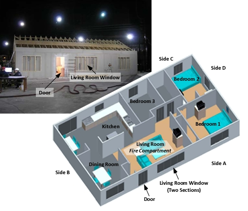
These tests were conducted in full-scale one and two-story, wood-frame structures constructed inside the UL laboratory in Northbrook, IL. Fires in the one-story structure were all started in the living room (see Figure 2) and involved typical contents found in a single-family home.

Figure 2: One-Story Structure and Floor Plan

As discussed in UL Tactical Implications Part 1 and Part 2, each of the fires during these tests quickly became ventilation controlled due to the fuel load within the buildings and limited ventilation provided by closed and intact doors and windows.

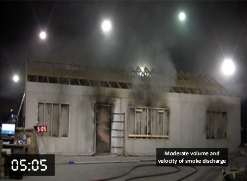
As each fire developed, the volume of smoke visible from the exterior and velocity of smoke discharge increased. This is consistent with fire development within the structure and increasing heat release rate, temperature, and volume of smoke production from the developing fire. Figure 3 illustrates exterior conditions at 05:05 during Test 5 conducted in the one-story residence.

Figure 3: Conditions at 05:05 (UL Test 5)

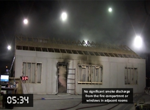
Interestingly, as the fire became ventilation controlled (as determined by both measurement of oxygen concentration and the heat release rate in the building), the volume and velocity of smoke discharge decreased to a negligible level as illustrated in Figure 4.

Figure 4: Conditions at 05:34 (UL Test 5)

This change occurred within a matter of 30 seconds! How might this influence firefighters’ perception of fire conditions inside the building if they arrived at 05:34 rather than 05:04? While presenting much the same as an incipient or early growth stage fire, conditions within the building at 05:34 are significantly ventilation controlled and increased ventilation resulted in rapid fire development and transition through flashover to a fully developed fire.

NIST Phoenix Warehouse Tests

In the Hazard of Ventilation Controlled Fires, I discussed a series of tests conducted by the National Institute for Standards and Technology (NIST) at an ordinary constructed warehouse in Phoenix, AZ. These tests were intended to develop information about performance of ordinary constructed buildings related to structural collapse. However, they also provided some interesting information regarding fire behavior.

One of the tests involved a fire in the front section of the warehouse that measured 50’ x 90’ (15.2 m x 27.4 m) with a height of 15’ (4.6 m) to the top of the pitched truss roof. The fuel load for this test included four stacks of 10 wood pallets and the interior finish and combustible structural elements of the building.  All doors and windows were closed at the start of the test.

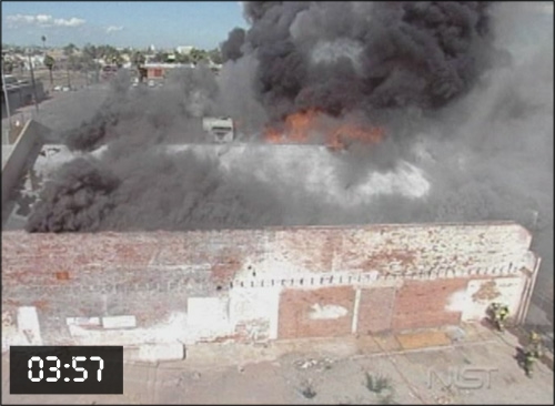
Figure 5 illustrates a large volume of dark gray to black smoke discharging from the roof of the structure and flames visible from roof ventilators at 03:57. The B-SAHF indicators visible n this photo indicate a significant growth stage fire within this building.

Figure 5. Conditions at 03:57 (NIST Warehouse Test)

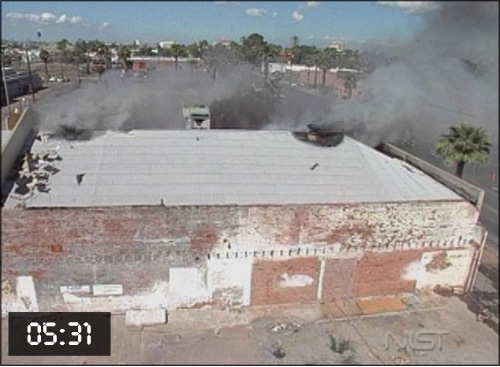
However, at 05:31 conditions visible on the exterior are quite different. The color and volume of smoke discharge (Smoke Indicators) as well as the velocity of discharge (Air Track Indicator) may lead firefighters to believe that this is an incipient or early growth stage fire. Nothing could be further from the truth. This fire is in the decay stage as a result of limited ventilation and any increase in ventilation will result in a rapid and significant increase in heat release rate!

Figure 6. Conditions at 05:31 (NIST Warehouse Test)

For more information on these tests see Structural Collapse Fire Tests: Single Story, Ordinary Construction Warehouse (Stroup, Madrzykowski, Walton, & Twilley, 2003) or view the videos of this series of tests at the NIST Structural Collapse webpage.

The Key

Heat release rate and temperature drop as the fire becomes ventilation controlled. Volume and velocity of smoke discharge are a function of pressure (given a constant opening size). Reduction in temperature and corresponding reduction in pressure will result in a smaller volume and lower velocity of smoke discharge.

When the temperature is the same, the velocity of discharge will likely be similar. Figure 1 shows that the temperature inside a compartment may be the same during the growth and decay stages of the fire. If the ventilation profile (number, size, and location of openings) remains the same, similar Smoke and Air Track indicators can be present.

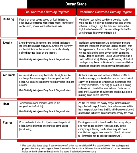
Decay stage incidators may be subtle. Consider the full range of B-SAHF inciators that may be observed under ventilation controlled, decay stage conditions (see Figure 7.

Figure 7. B-SAHF Decay Stage Indicators.

Durango, Colorado Commercial Fire

CFBT-US developed a case study examining an extreme fire behavior event that occurred during a commercial fire in Durango, CO in 2008 injuring nine firefighters and fire officers. The reporting party indicated that there was a large amount of dark smoke coming from the roof of the building. However, when firefighters arrived, they found nothing showing but a small amount of light colored smoke. Why might this have been the case?

Download a copy of the Fire Behavior Case Study: Durango CO Commercial Fire and see if this may have been a result of similar fire development and presentation of fire behavior indicators as seen in the UL and NIST tests!

Ed Hartin, MS, EFO, MIFireE, CFO

References

Kerber, S. (2011). Impact of ventilation on fire behavior in legacy and contemporary residential construction. Retrieved July 16, 2011 from http://www.ul.com/global/documents/offerings/industries/buildingmaterials/fireservice/ventilation/DHS%202008%20Grant%20Report%20Final.pdf.

Stroup, D., Madrzykowski, D., Walton, W., & Twilley, W. (2003). Structural collapse fire tests: Single story, ordinary construction warehouse, NISTIR 6959. Retrieved July 16, 2011 from http://www.nist.gov/customcf/get_pdf.cfm?pub_id=861215

Reading the Fire 15

Monday, November 29th, 2010

Greetings from Peru! I am writing this post in the kitchen of Station #100 in San Isidro, which is one of the districts in Lima. I am in Lima to speak on the concepts of practical fire dynamics and 3D Firefighting at a fire and rescue conference later in the week.

I would like to extend special thanks the Station Chief Paul Zarak and the members of Station 100 for making me welcome in their house. Paul and my friend Daniel Bacigalupo of Lima Station 4 picked me up at the airport and provided me with a great welcome to the Peru and the City of Lima.

Reading the Fire-The Journey Continues

Developing and maintaining proficiency in reading the Fire using the B-SAHF (Building, Smoke, Air Track, Heat, and Flame) organizing scheme for fire behavior indicators, requires practice. This post provides an opportunity to exercise your skills using a video segment shot during a fire in a detached garage. While a fairly simple incident, remember that the description of many tragic events begin with the words “it appeared to be a routine incident”. There are no routine incidents

This post examines fire development during a fire in a detached garage with an exposed dwelling on Side C which occurred in Lake Station, Indiana. The video begins prior to the start of firefighting operations.

Download and the B-SAHF Worksheet.

Watch the first 25 seconds (0:25) of the video. First, describe what you observe in terms of the Building, Smoke, Air Track, Heat, and Flame Indicators; then answer the following five standard questions?

  1. What additional information would you like to have? How could you obtain it?
  2. What stage(s) of development is the fire likely to be in (incipient, growth, fully developed, or decay)?
  3. What burning regime is the fire in (fuel controlled or ventilation controlled)?
  4. What conditions would you expect to find inside this building?
  5. How would you expect the fire to develop over the next two to three minutes

watch the next 20 seconds (from 0:25 to 0:40). How do the B-SAHF indicators change? Why might this be the case?

Watch 20 seconds the video showing conditions at the doorway on Side B starting 50 seconds (0:50 to 1:10). Are the indicators visible from this vantage point similar to those on Side A? Why or why not?

Now watch the video up until the arrival of the first engine company (at 1:25). How do you think fire conditions are changing inside the garage? Is the heat release increasing, decreasing, or remaining relatively constant? Why?

Continue watching the video until 3 minutes 45 seconds (3:20). How do the smoke and air track indicators change (both before and after the overhead door on Side A was opened)?

At approximately 4:18 flames become visible from a window on Side C? Is this surprising? Why or why not?

How is a fire in a garage different than a fire in the living areas of a dwelling? How might these differences influence fire behavior and impact on firefighter safety?

Reading the Fire

See the following posts for more information on reading the fire:

Next Post

At breakfast this morning, I met Commander Oscar Ruiz member at Lima Station 4 and former Chief of Station 100. In 1997, Oscar was injured as the result of a backdraft while operating in the basket of an aerial platform at a commercial fire in the Victoria district of Lima. My next post will examine this incident and important lessons learned.

Ed Hartin, MS, EFO, MIFIreE, CFO

Homewood, IL LODD: Part 2

Sunday, November 21st, 2010

This post continues examination of the incident that took the life of Firefighter Brian Carey and seriously injured Firefighter Kara Kopas on the evening of March 30, 2010  while they were operating a hoseline in support of primary search in a small, one-story, wood frame dwelling with an attached garage at 17622 Lincoln Avenue in Homewood, Illinois.

This post focuses on firefighting operations, key fire behavior indicators, and firefighter rescue operations implemented after rapid fire progression that trapped Firefighters Carey and Kopas.

Firefighting Operations

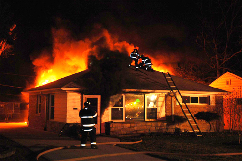
After making initial assignments, the Incident Commander performed reconnaissance along Side Bravo to assess fire conditions. Fire conditions at around the time the Incident Commander performed this reconnaissance are illustrated in Figure 7. After completing recon of Side B, the Incident Commander returned to a fixed command position in the cab of E-534 (in order to monitor multiple radio frequencies).

Figure 7. Conditions Viewed from Side C during the Incident Commander’s Recon

Note: John Ratko Photo from NIOSH Death in the Line of Duty Report F2010-10.

Engine 1340 (E-1340) arrived and reported to Command for assignment. The five member crew of this company was split to assist T-1220 with vertical ventilation, horizontally ventilate through windows on Sides B and D, and to protect Exposures D and D2.

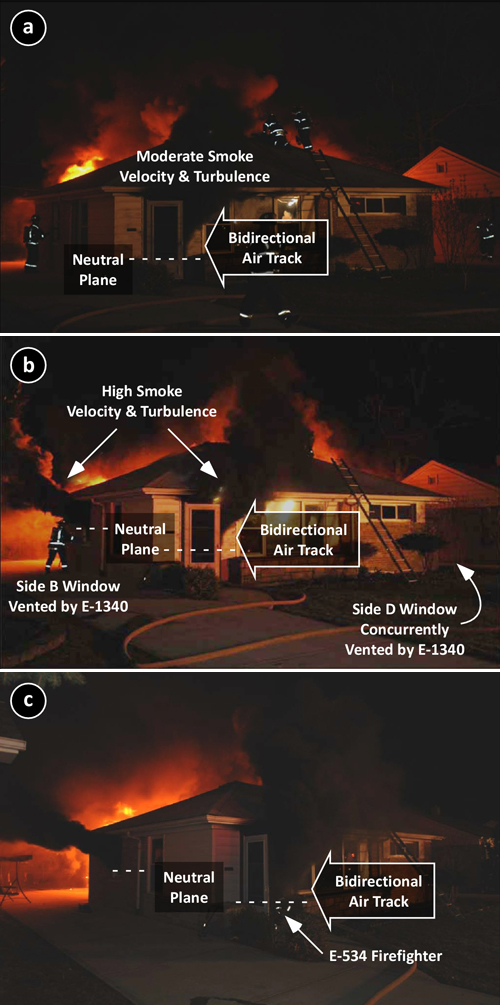
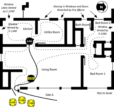
One member of E-1340 assisted T-1220 and the remaining members vented the kitchen windows on SidesD and B, while the E-1340 Officer stretched a 1-3/4” (45 mm) hoseline from E-534 to protect exposures on Side D. However, this line was not charged until signficantly later in the incident (see Figure 14). Figure 8 (a-c) illustrates changing conditions as horizontal ventilation is completed on Sides B and D.

Figure 8. Sequence of Changing Conditions Viewed from the A/B Corner

At 2105 Command reported that crews were conducting primary search and were beginning to vent.

Note the B-SAHF indicators visible from the A/B Corner in Figure 8a: Dark gray smoke from the door on Side A with the neutral plane at approximately 18” (0.25 m) above the floor. Velocity and turbulence are moderate and a bidirectional air track is evident at the doorway.

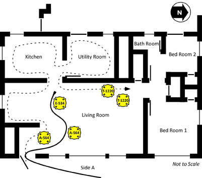
As the 2-1/2” (64 mm) handline reached the kitchen, flames were beginning to breach the openings in the Side C wall of the house and thick black smoke had banked down almost to floor level. As noted in Figure 3 (and subsequent floor plan illustrations), there were doors and windows between the house and addition in the Utility Room and Bedroom 2 . The Firefighter from E-534 had a problem with his protective hood and handed the nozzle off to Firefighter Carey and instructed him to open and close the bail of the nozzle quickly. After doing so, the Firefighter from E-534 retreated along the hoseline to the door on Side A to correct this problem (he is visible in the doorway in Figure 8c).

As E-1340 vents windows on Sides B (see Figure 8b) and D, the level of the neutral plane at the doorway on Side A lifts, but velocity and turbulence of smoke discharge increases. Work continues on establishing a vertical vent, but is hampered by smoke discharge from the door on Side A.

After horizontal ventilation of Sides B and D, velocity and turbulence of smoke discharge continues to increase and level of the upper layer drops to the floor as evidenced by the neutral plane at the door on Side A (see Figures 8b and 8c)

The photo in Figure 8c was taken just prior to the rapid fire progression that trapped Firefighters Carey & Kopas. The Firefighter from E-534 is visible in the doorway correcting a malfunction with his protective hood.

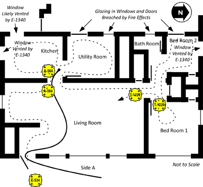
As T-1220B reached the hallway leading to the bedrroms, they felt a significant increase in temperature and visibility worsened. After searching Bedroom 2 and entering Bedroom 1 temperature contiued to increase and T-1220B observed flames rolling through the upper layer in the hallway leading from Bedroom 2 and the Bathroom. Note: NIOSH Death in the Line of Duty Report 2010-10 does not specify if T-1220B searched Bedroom 2, but this would be consistent with a left hand search pattern. They immedidately retreated to the Living Room looking for the hoseline leading to the door on Side A. As they did so, they yelled to the crew on the 2-1/2” (64 mm) handline to get out.

Extreme Fire Behavior

Firefighter Kopas felt a rapid increase in temperature as the upper layer ignited throughout the living room and the fire in this compartment transitioned to a fully developed stage. She yelled to Firefighter Carey, but received no response as she turned to follow the 2-1/2” (64 mm) hoseline back to the door on Side A. She made it to within approximately 4’ (1.2 m) of the front door when her protective clothing began to stick to melted carpet and she became stuck. T-1220B saw that she was trapped, reentered and pulled her out.

Figure 12. Position of the Crews as the Extreme Fire Behavior Phenomena Occurred

Note: It is unknown if T-1220B searched Bedroom 2 before entering Bedroom 1. However, this would be consistent with a left hand search pattern.

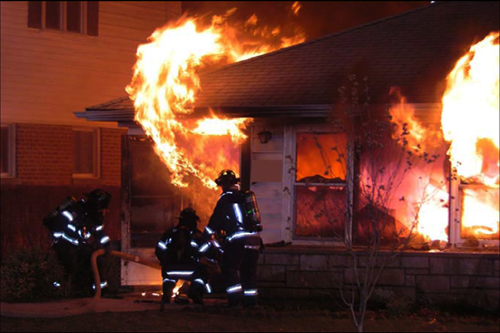
Figure 13. Conditions Viewed from the Alpha/Bravo Corner as the Extreme Fire Behavior Occured

Note: Warren Skalski Photo from NIOSH Death in the Line of Duty Report F2010-10.

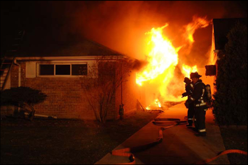
Figure 14. Conditions Viewed from the Alpha/Delta Corner as the Extreme Fire Behavior Occured

Note: Warren Skalski Photo from NIOSH Death in the Line of Duty Report F2010-10.

Following the transition to fully developed fire conditions in the living room, the Incident Commander ordered T-1220 off the roof. As illustrated in Figure 14, the exposure protection line stretched by E-1340 was not charged until after Firefighter Carey was removed from the building.

Figure 15. Position of Search and Fire Control Crews after Rapid Fire Progress

Firefighter Rescue Operations

The Incident Commander and Firefighter from E-534 (who had retreated to the door due to a problem with his protective hood), pulled a second 1-3/4” (45 mm) line from E-534. T-1220B re-entered the house with this hoseline to locate Firefighter Carey.

While advancing into the living room, T-1220B discovered that E-534’s 2-1/2” (64 mm) handline. They controlled the fire in the living room using a direct attack on burning contents and advanced to the kitchen where they discovered Firefighter Carey entangled in the 2-1/2” (64 mm) handline. Firefighter Carey’s helmet and breathing apparatus facepiece were not in place.

T-1220B removed Firefighter Carey from the building where he received medical care from T-1145. A short time later, Firefighter Carey became apenic and pulseless. After the arrival of Ambulance 2101 (A-2101), Firefighter Carey was transported to Advocate South Suburban Hospital in Hazel Crest, IL where he was declared dead at 10:03 pm.

According to the autopsy report, Firefighter Carey had a carboxyhemoglobin (COHb) of 30% died from carbon monoxide poisoning. The NIOSH Death in the Line of Duty Report (2010) did not indicate if the medical examiner tested for the presence of hydrogen cyanide (HCN) or if thermal injuries were a contributing factor to Firefighter Carey’s death.

Timeline

Review the Homewood, Illinois Timeline (PDF format) to gain perspective of sequence and the relationship between tactical operations and fire behavior.

Contributing Factors

Firefighter injuries often result from a number of causal and contributing factors. NIOSH Report F2010-10 identified the following contributing factors in this incident that led to the death of Firefighter Brian Carey and serious injuries to Firefighter Kara Kopas.

  • Well involved fire with trapped civilian upon arrival.
  • Incomplete 360o situational size-up
  • Inadequate risk-versus-gain analysis
  • Ineffective fire control tactics
  • Failure to recognize, understand, and react to deteriorating conditions
  • Uncoordinated ventilation and its effect on fire behavior
  • Removal of self-contained breathing apparatus (SCBA) facepiece
  • Inadequate command, control, and accountability
  • Insufficient staffing

Questions

The following questions focus on fire behavior, influence of tactical operations, and related factors involved in this incident.

  1. What type of extreme fire behavior phenomena occurred in this incident? Why do you think that this is the case (justify your answer)?
  2. How did the conditions necessary for this extreme fire behavior event develop (address both the fuel and ventilation sides of the equation)?
  3. What fire behavior indicators were present in the eight minutes between arrival of the first units and occurrence of the extreme fire behavior phenomena (organize your answer using Building, Smoke, Air Track, Heat, and Flame (B-SAHF) categories)? In particular, what changes in fire behavior indicators would have provided warning of impending rapid fire progression?
  4. Did any of these indicators point to the potential for extreme fire behavior? If so, how? If not, how could the firefighters and officers operating at this incident have anticipated this potential?
  5. What was the initiating event(s) that lead to the occurrence of the extreme fire behavior that killed Firefighter Carey and injured Firefighter Kopas?
  6. How did building design and construction impact on fire behavior and tactical operations during this incident?
  7. What action could have been taken to reduce the potential for extreme fire behavior and maintain tenable conditions during primary search operations?
  8. How would you change, expand, or refine the list of contributing factors identified by the NIOSH investigators?

Homewood, IL LODD

Saturday, November 13th, 2010

Introduction

While formal learning is an essential part of firefighters’ and fire officers’ professional development, informal learning is equally important, with lessons frequently shared through the use of stores. Stories are about sharing knowledge, not simply about entertainment. It is their ability to share culture, values, vision and ideas that make them so critical. They can be one of the most powerful learning tools available (Ives, 2004). “Only by wrestling with the conditions of the problem at hand and finding his own way out, does [the student] think” (Dewey, 1910, p. 188).

Developing mastery of the craft of firefighting requires experience. However, it is unlikely that we will develop the base of knowledge required simply by responding to incidents. Case studies provide an effective means to build our knowledge base using incidents experienced by others. This case is particularly significant as the circumstances could be encountered by almost any firefighter.

Aim

Firefighters and fire officers recognize and respond appropriately to the hazards of ventilation controlled fires in small, Type V (wood frame), single family dwellings.

References

National Institute for Occupationsl Safey and Health (NIOSH). (2010). Death in the line of duty: Report F2010-10. Retrieved October 22, 2010 from http://www.cdc.gov/niosh/fire/pdfs/face201010.pdf.

Ives, B. (2004) Storytelling and Knowledge Management: Part 2 – The Power of Stories. Retrieved May 6, 2010 from http://billives.typepad.com/portals_and_km/2004/08/storytelling_an_1.html

Dewey, J. (1910) Democracy and education. New York: McMillan

Learning Activity

Review the incident information and discuss the questions provided. Focus your efforts on understanding the interrelated impact of ventilation and fire control tactics on fire behavior. Even more important than understanding what happened in this incident is the ability to apply this knowledge in your own tactical decision-making.

The Case

This case study was developed using NIOSH Death in the Line of Duty: Report F2010-10 (NIOSH, 2010).

On the evening of March 30, 2010, while operating at a fire in a small single family dwelling, Firefighter/Paramedic Brian Carey and Firefighter/Paramedic Kara Kopas were assigned to assist in advancement of a 2-1/2” handline for offensive fire attack and to support primary search. Shortly after entering the building conditions deteriorated and they were trapped by rapid fire progression. Firefighter Kopas suffered 2nd and 3rd degree burns to her lower back, buttocks, and right wrist. Firefighter Carey died from carbon monoxide poisoning and inhalation of smoke and soot. A 84 year old male civilian occupant also perished in the fire.

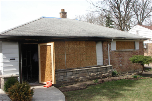
Figure 1. Side A Post Fire

Side A Post Fire

Note: National Institute for Occupational Safety and Health (NIOSH)

Building Information

This incident involved a 950 ft2 (88.26 m2), one-story, single family dwelling constructed in 1951. The house was of Type V (wood frame) construction with a hip roof covered with asphalt shingles. The roofline of the hip roof provided a small attic space. Sometime after the home was originally constructed an addition C was built that attached the house to a garage located on Side C. Compartment linings were drywall. The house, garage, and addition were all constructed on a concrete slab.

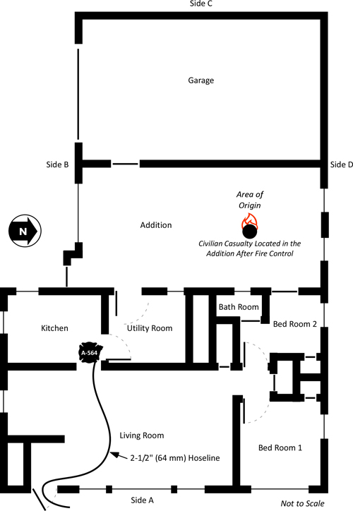
There were several openings between the house and addition, including two doors, and two windows (see Figure 3).

Note: The number and nature of openings between the garage and addition is not reported, but likely included a door and possibly a window (given typical garage construction). NIOSH investigators did not determine if the doors and windows between the house, addition, and garage were open or closed at the time of the fire as they were consumed by the fire and NIOSH did not interview the surviving occupant (S. Wertman, personal communication, November 17, 2010). The existence and position of the door shown in the wall between the addition and garage is speculative (based on typical design features of this type of structure).

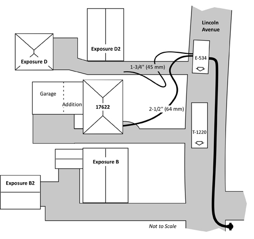
Figure 2. Plot Plan and Apparatus Positioning

Figure 3. Floor Plan 17622 Lincoln Avenue

The Fire

Investigators believe that the fire originated in an addition that was constructed between the original home and the two-car garage. The surviving occupant reported that she observed black smoke and flames from underneath the chair that her disabled husband was sitting in.

The addition was furnished as a family room and fuel packages included upholstered furniture and polyurethane padding. The civilian victim also had three medical oxygen bottles (one D Cylinder (425 L) and two M-Cylinders (34 L). It is not know if the oxygen in these cylinders was a factor in fire development. The garage contained a single motor vehicle in the garage and other combustible materials.

After calling 911 and attempting to extinguish the fire, the female occupant exited the building. NIOSH Death in the Line of Duty Report 2010-10 did not specify this occupants egress path or if she left the door through which she exited open or closed (NIOSH did not interview the occupant, she was interviewed by local fire and law enforcement authorities). The NIOSH investigator (personal communications S. Wertman, November 17, 2010) indicated that the occupant likely exited through the exterior door in the addition or through the door on Side A. Give rapid development through flashover in the addition, it is likely that the exterior door in the addition or door to the garage was open, pointing to the likelihood that the occupant exited through this door. Subsequent rapid extension to the garage was likely based on design features of the addition and garage or some type of opening between these two compartments. As similar extension did not occur in the house, it is likely that the door and windows in the Side C wall of the house were closed.

In the four minutes between when the incident was reported (20:55 hours) and arrival of a law enforcement unit (20:59), the fire in the addition had progressed from the incipient stage to fully developed fire conditions in both the addition and garage.

Dispatch Information

At 2055 hours on March 30, 2010, dispatch received a call from a resident at 17622 Lincoln Avenue stating that her paralyzed husband’s chair was on fire and that he was on oxygen. The first alarm assignment consisting of two engines, two trucks, a squad, and ambulance, and fire chief was dispatched at 2057.

Table 1. On-Duty and Additional Unit Staffing of First Alarm Resources

Unit

Staffing

Engine 534 Lieutenant, Firefighter, Engineer
Ambulance 564 2 Firefighter Paramedics
Truck 1220 (Auto Aid Department) Lieutenant, 2 Firefighters, Engineer
Engine 1340 (Auto Aid Department) Lieutenant 3 Firefighters, Engineer
Truck 1145 (Auto Aid Department) Lieutenant, 2 Firefighters, Engineer
Squad 440 (Auto Aid Department) Lieutenant, 3 Firefighters
Chief Chief

Note: This table was developed by integrating data from Death in the Line of Duty Report 2010-10 (NIOSH, 2010).

Weather Conditions

The weather was clear with a temperature of 12o C (53o F). Firefighters operating at the incident stated that wind was not a factor.

Conditions on Arrival

A law enforcement officer arrived prior to fire companies and reported that the house was “fully engulfed” and that the subject in the chair was still in the house.

Truck 1220 (T-1220) arrived at 2101, observed that the fire involved a single family dwelling, and received verbal reports from law enforcement and bystanders that the male occupant was still inside. Note: The disabled male occupant’s last known location was in the addition between the house and garage, but it is unknown if this information was clearly communicated to T-1220 or to Command (E-534 Lieutenant).

Engine 534 (E-534) arrived just behind T-1220 and reported heavy fire showing. E-534 had observed flames from Side C during their response and discussed use of a 2-1/2” (64 mm) handline for initial attack.

Firefighting Operations

Based on the report of a trapped occupant, T-1220B (Firefighter and Apparatus Operator) prepared to gain entry and conduct primary search. Note: Based on data in NIOSH Death in the Line of Duty Report 2010-10, it is not clear that this task was assigned by the initial Incident Commander (Engine 534 Lieutenant). It appears that this assignment may have been made by the T-1220 Lieutenant, or performed simply as a default truck company assignment for offensive operations at a residential fire.

Upon arrival, the E-534 Lieutenant assumed Command and transmitted a size-up report indicating heavy fire showing. The Incident Commander(E-534 Lieutenant) assisted the E-534 Firefighter with removal of the 1-3/4” (45 mm) skid load from the solid stream nozzle on the 2-1/2” (64 mm) hose load and stretching the 2-1/2” (64 mm) handline to the door on Side A. The E-534 Apparatus Operator charged the line with water from the apparatus tank and then hand stretched a 5” supply line to the hydrant at the corner of Lincoln Avenue and Hawthorne Road with the assistance of a Firefighter from T-1220.

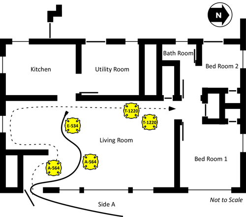
Figure 4. Initiation of Primary Search

The Incident Commander (E-534 Lieutenant) assisted T-1220B in forcing the door on Side A. T-1220B made entry without a hoseline and began a left hand search as illustrated in Figure 4, noting that the upper layer was banked down to within approximately 3’ (0.9 m) from the floor).

Arriving immediately after E-534, the crew of A-564 donned their personal protective equipment and reported to the Incident Commander at the door on Side A, where he and the E-534 Firefighter were preparing to make entry with the 2-1/2” hoseline. The Incident Commander then assigned A-564 to work with the E-534 Firefighter to support search operations and control the fire.

T-1220 initiated roof operations and began to cut a ventilation opening on Side A near the center of the roof. Note: Based on data in NIOSH Death in the Line of Duty Report 2010-10, it is not clear that this task was assigned by the initial Incident Commander (Engine 534 Lieutenant). It appears that this assignment may have been made by the T-1220 Lieutenant, or performed simply as a default truck company assignment for offensive operations at a residential fire.

As illustrated in Figure 5, a large body of fire can be observed on Side C and a bi-directional air track is evident at the point of entry on Side A with dark gray smoke pushing from the upper level of the doorway at moderate velocity. All windows on Sides A and B were intact, with evidence of soot and/or condensed pyrolizate on the large picture window adjacent to the door on Side A.

Figure 5. Conditions Viewed from the Alpha/Bravo Corner at Approximately

Note: Warren Skalski Photo from NIOSH Death in the Line of Duty Report F2010-10.

The Firefighter from E-534 took the nozzle and assisted by Firefighters Carey and Kopas (A-564) stretched the 2-1/2” (64 mm) handline through the door on Side A and advanced approximately 12’ (3.66 m) into the kitchen. As they advanced the hoseline, they were passed by T-1220B, conducting primary search. The E-534 Firefighter, Firefighter Kopas (A-564), and T-1220B observed thick (optically dense), black smoke had dropped closer to the floor and that the temperature at floor level was increasing.

Figure 6. Primary Search and Fire Control Crews

Questions

Take a few minutes and consider the answers to the following questions. Remember that it is much easier to sort through the information presented by the incident when you are reading a blog post, than when confronted with a developing fire with persons reported!

  1. What B-SAHF (Building, Smoke, Air Track, Heat, & Flame) indicators were observed during the initial stages of this incident?
  2. What stage(s) of fire and burning regime(s) were present in the building when T-1220 and E-534 arrived? Consider potential differences in conditions in the addition, garage, kitchen, bedrooms, and living room?
  3. What would you anticipate as the likely progression of fire development over the next several minutes? Why?
  4. How might tactical operations (positively or negatively) influence fire development?

Ed Hartin, MS, EFO, MIFireE, CFO

Note: The number and nature of openings between the garage and addition is not reported, but likely included a door and possibly a window (given typical garage construction). NIOSH investigators did not determine if the doors and windows between the house, addition, and garage were open or closed at the time of the fire as they were consumed by the fire and NIOSH did not interview the surviving occupant (S. Wertman, personal communication, November 17, 2010). The existence and position of the door shown in the wall between the addition and garage is speculative (based on typical design features of this type of structure).

Gas Cooling: Part 4

Sunday, September 12th, 2010

Reading the Fire

Before returning to discussion of the science underlying gas cooling as a fire control technique, I wanted to share a video of an industrial fire in Maidencreek Township, Pennsylvania that provides an excellent illustration of smoke and air track indicators. Watch the first minute (1:00) of the video and answer the following questions:

  • Consider how you would read the smoke and air track indicators (particularly the level of the neutral plane and velocity) if this was a single family dwelling. How is air track indicators are different in a large building (with multiple ventilation openings) such as was the case in this incident?
  • What stage of development (incipient, growth, fully developed, or decay) and burning regime (fuel or ventilation controlled) is this fire in?
  • Watch the remainder of the video and examine the effectiveness of the master stream application? Are the streams effective? Why or why not? What could be done to increase the effectiveness of application?

For additional information on reading the fire, see the following posts:

Gas Laws

Paraphrasing Albert Einstein, British science writer Simon Singh stated that, “Science has nothing to do with common sense. Common sense is a set of prejudices” (Capps, 2010, p. 115). One of the challenges faced by firefighters engaging with the science of their craft is the common sense understanding of the fire environment and firefighting practices. This post continues examination of gas cooling as a fire control technique, by peeling off a few more layers and digging deeper into the underlying science related to the behavior of gases.

Readers who have worked through Gas Cooling Part 1, Part 2, and Part 3 have a reasonable idea how a small volume of water can reduce the temperature of the upper layer in a compartment and also reduce the volume of the upper layer (raising the level of the lower boundary of the layer). In addition, readers are likely to also understand the limitations of the simple explanation provided in prior posts.

In Water and Other Extinguishing Agents (Särdqvist,2002), Dr. Stefan Särdqvist provides a fairly detailed explanation of volume changes during smoke cooling and examines how the percentage of water vaporizing in the upper layer influences these changes. Understanding Stefan’s explanation requires a good understanding of the ideal gas law and a willingness to work through the math.

Gas Laws

The introduction to the gas laws and overview of Charles’s Law was provided in Gas Cooling: Part 3. This content has been repeated in this post, to save you from going back to the previous post.

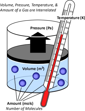
While gases have different characteristics and properties, the behavior of gases can be described in general terms using the ideal gas law. This physical law describes the relationship between absolute temperature, volume, and pressure of a given amount of an ideal gas.

Figure 1. Temperature, Volume, Pressure & Amount

The concept of an ideal gas is based on the following assumptions:

  • Gases consist of molecules in random motion
  • The volume of the molecules is negligible in comparison to the total volume occupied by the gas
  • Intermolecular forces (i.e., attractive forces between molecules) are negligible
  • Pressure is the result of gas molecules colliding with the walls of its container

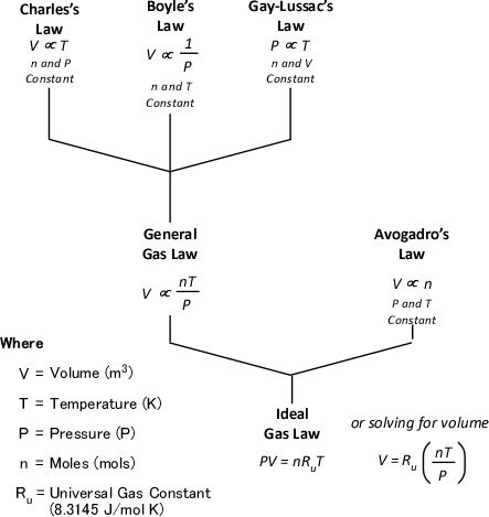
The ideal gas law is actually a synthesis of several other physical laws that each describes a single characteristic of the behavior of gases in a closed system (enclosed in some type of container).

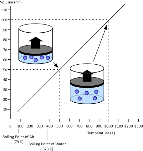
Charles’s Law: In the 1780s, French scientist Jacques Charles studied the effect of temperature on a sample of gas at a constant pressure. Charles found that as the gas was heated, the volume increased. As the gas was cooled, the volume decreased. This finding gave rise to Charles’s Law which states that at a constant pressure the volume of a given amount (mass or number of molecules) of an ideal gas increases or decreases in direct proportion with its absolute (thermodynamic) temperature. The symbol  is used to express a proportional relationship (much the same as = is used to express equality), so this relationship can be expressed as:

Where:

V=Volume

T=Temperature

When two values (such as volume and temperature in Charles’s Law) are proportional, one is a consistent multiple of the other. For example If one value was consistently eight times the other, the values would also be proportional. In the case of Charles’s Law when the absolute temperature of a gas doubles, the pressure doubles. Figure 2 illustrates the relationship between absolute temperature in Kelvins (K) and volume in cubic millimeters (mm3).

Figure 2. Charles’s Law

This relationship can also be stated using the following equation:

Where

V=Volume

T=Temperature

Subscript of 1 refers to initial conditions

Subscript of 2 refers to final conditions

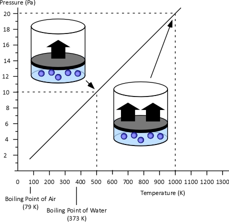
Gay-Lussac’s Law: When Jacques Charles discovered the relationship between temperature and volume, he also discovered a similar relationship between temperature and pressure. However, Charles never published this discovery. Charles’s work on temperature and pressure was recreated by French chemist Joseph-Louis Gay-Lussac. Gay Lussac’s Law states that if the volume of an ideal gas is held constant, the pressure of a given amount (mass or number of molecules) of an ideal gas increases or decreases proportionally with its absolute temperature. As with Charles’s Law, Gay-Lussac’s law can be expressed mathematically as:

Where

V=Volume

P=Pressure

Figure 3. Gay-Lussac’s Law

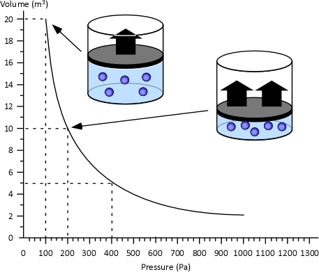
Boyle’s Law: in the 1660s, Irish physicist Robert Boyle studied the relationship of pressure and volume of gases. Boyle discovered that as pressure on a gas was increased, its volume decreased. Boyle’s Law states that if the temperature of an ideal gas is held constant, the pressure and volume of a given amount (mass or number of molecules) of an ideal gas are inversely proportional, as pressure increases, the volume occupied by the gas decreases. Boyle’s Law can be expressed mathematically as:

Where:

V=Volume

P=Pressure

Figure 4. Boyle’s Law

General Gas Law: The General Gas Law simply integrates Charles’s, Gay-Lussac’s, and Boyle’s Laws to state that the volume of an ideal gas is proportional to the amount (number of molecules) and absolute temperature and inversely proportional to pressure. The General Gas Law can be expressed mathematically as:

Where:

V=Volume

n=Mole (mol)

T=Temperature

P=Pressure

The General Gas Law defines the amount of gas in terms of the number of molecules, measured in moles (which has nothing to do with the animal having the same name).

Mole: While related to Avogadro’s Law, the term mole as a unit of measure was conceived by German chemist Wilhelm Ostwald in 1893. Unlike liters or grams, a mole is not a unit of volume or mass, but a counting unit. A mole is defined as the quantity of anything that has the same number of particles found in 12 grams of carbon-12. As atoms and molecules are extremely small, a mole is a large number of molecules. Specifically a mole contains 602,510,000,000,000,000,000,000 (more commonly written 6.0251 x 10²³ in scientific notation) molecules of a substance. The number of moles of a substance is denoted by the letter n. In SI units, a kilogram mole (Kmol) is often used instead of the mole. A Kmol is 1000 mol or 6.0251 x 1026 molecules of a substance.

It may seem that using the mole to measure an amount of a substance makes this more complicated. After all, why not use a measure of volume such as liters or cubic meters or mass such as grams or kilograms? Chemical formula (such as H2O for water) describes the makeup of a chemical compound in terms of the numbers of atoms of each element comprising a single molecule of the substance.

While not a unit of mass, moles can be related to mass (just as you can determine the mass of a dozen eggs of a given size, by multiplying the mass of one of the eggs by 12).

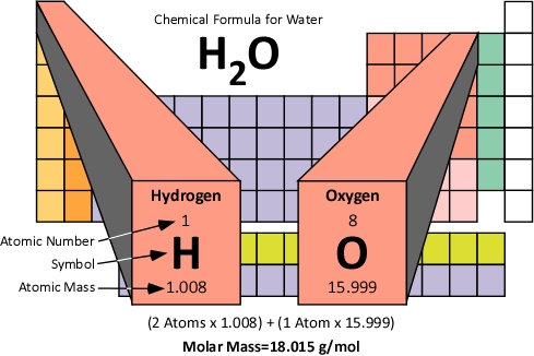
Molar Mass: The molar mass of a compound is the mass of 1.0 moles of the substance in grams. Molar mass is determined by the sum of the standard atomic weights of the atoms which form the compound multiplied by the molar mass constant (Mu) of 1 g/mol. Figure 5 illustrates how the molar mass of water is calculated.

Figure 5. Molar Mass of Water

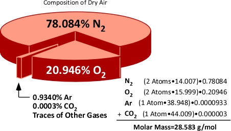
Molar mass can also be calculated for mixtures of substances. When dealing with mixtures, the molar mass of each constituent is calculated and applied proportionately on the basis of the percentage of that substance in the mixture. For example air is comprised of 78% Nitrogen, 21% Oxygen, and 1% of other gases such as Argon (Ar) and Carbon Dioxide (CO2). Nitrogen (N2) and Oxygen (O2) molecules are each comprised of two atoms (and are referred to as diatomic molecules). This means that the molar mass of Nitrogen and Oxygen molecules is twice the atomic mass.

Figure 6. Molar Mass of Air

Hopefully how the concepts of the mole and molar mass can be applied will become clear after examining the expansion of water when turned to steam and application of the gas laws to integrate steam expansion and changes in volume of the upper layer during gas cooling under a variety of circumstances.

Avogadro’s Law: In 1811, Italian physicist and mathematician Amedeo Avogadro published a theory regarding the relationship of the number of molecules in a gas if temperature, pressure, and volume are held constant. Avogadro’s Law states that samples of ideal gasses, at the same absolute temperature, pressure and volume, contain the same number of molecules regardless of their chemical nature and physical properties. More specifically, at a temperature of 273 K (0oC) and absolute pressure of 101300 Pa, 22.41 L (0.001 m3) of an ideal gas contains 6.0251 x 10²³ molecules (1.0 mol)

Ideal Gas Law: This gas law integrates Avogadro’s law with the Combined Gas Law. If the number of molecules in a specific volume of an ideal gas at a consistent temperature and pressure (273 K and 101300 Pa) is always the same, then the proportional relationship between pressure, volume, temperature, and amount can be defined as having a constant value (Universal Gas Constant).

Where:

P=Pressure (Pa)

V= Volume (m3)

T=Temperature (K)

n=Moles

Ru=Universal Gas Constant (8.3145 J/mol K)

Universal Gas Constant (Ru): This physical constant identifies the internal kinetic energy per mole of an ideal gas for each Kelvin of temperature (J/mol K). As it is universal this constant is the same for all gases that demonstrate the properties of an ideal gas.

If the pressure, volume, and temperature of an ideal gas can be observed and Avogadro’s Law is accepted as being true (making the amount of gas also known), the value of the Universal Gas Constant can be determined empirically (based on observation) by solving the ideal gas law equation for Ru.

Where:

V=Volume

Ru=Universal Gas Constant

n=Moles

T=Temperature

P=Pressure

Figure 7 illustrates each of the gas laws and how they are integrated into the Ideal Gas Law.

Figure 7. Gas Laws

Application-Steam Expansion

As stated in Gas Cooling: Part 3, the 5th Edition of the Essentials of Firefighting (IFSTA, 2008) states that the volume of water expands 1700 times when it is converted to steam at 100o C (212o F). However, this information is presented as a fact to be memorized and no explanation is provided as to why this is the case or that if temperature is increased further, that the volume of steam will continue to expand. In the previous post, I asked the reader to accept this assumption with assurance that an explanation would follow. Application of the ideal gas law to expansion of steam provides an excellent opportunity to exercise your understanding of the gas laws and other scientific concepts presented in this post.

What we know:

  • Molecular Mass of Water: 18 g/mol
  • Boiling Point of Water at Atmospheric Pressure: 100o C (373.15 K)
  • Density of Water at 20o C (293.15 K): 1000000 g/m3
  • Atmospheric Pressure: 101325 Pa
  • Ideal Gas Constant (Ru): 8.3145 J/mol K

What we need to find out:

  1. What is the volume of 1 mole of steam
  2. What is the density (mass per unit volume) of steam at 100o C
  3. What is the ratio between the density of water and the density of steam at 100o C

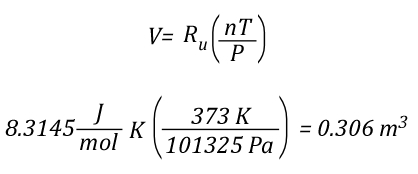
The volume of 1 mole of pure steam can be calculated by solving the ideal gas equation for V.

As 1 mole of water (in the liquid or gaseous phase) contains the same number of molecules, it’s molar mass will be the same. 1 mole of water has a mass of 18 grams. Density is calculated by dividing mass by volume, so the density of steam at 100o C can be calculated as follows:

Dividing the density of water by the density of steam at 100o C determines the expansion ratio when a specific mass of water is vaporized into steam at this temperature.

This means that if a specific mass of water is vaporized into steam at 100o C, its volume will expand 1700 times. So the 5th Edition of the Essentials of Firefighting (IFSTA, 2008) is correct, but now you know why. However, what would happen if the steam continued to absorb energy from the upper layer and its temperature increased from 100o C to 300o C, the mass of the steam would remain the same, but what would happen to the volume? You can use the Ideal Gas Law to solve this question as well.

The Next Step

Just as the Ideal Gas Law can be used to determine the expiation ratio of steam, it can also be used to calculate contraction of the upper layer as it is cooled. The next post will examine how Dr. Stefan Särdqvist integrates these two calculations to determine changes in the volume of the upper layer under a variety of conditions.

New Book

Greg Gorbett and Jim Phar of Eastern Kentucky University (EKU) have written a textbook titled Fire Dynamics focused on meeting the Fire and Emergency Services Higher Education (FESHE) curriculum requirements for Fire Behavior and Combustion. I just received my copy and at first glance it appears to be an excellent work (as I would expect from these outstanding fire service educators). One useful feature of the text is a basic review of math, chemistry, and physics as it relates to the content of the course. I will be dong a more detailed review of the book in a subsequent post, but wanted to give readers of the CFBT-US Blog a heads up that it had been released.

Ed Hartin, MS, EFO, MIFireE, CFO

References

International Fire Service Training Association (IFSTA). (2008). Essentials of firefighting (5th ed). Stillwater, OK: Fire Protection Publications.

Särdqvist, S. (2002) Water and other extinguishing agents. Karlstad, Sweden: Räddnings Verket

Reading the Fire 14

Sunday, August 1st, 2010

Developing and maintaining proficiency in reading the Fire using the B-SAHF (Building, Smoke, Air Track, Heat, and Flame) organizing scheme for fire behavior indicators, requires practice. This post provides an opportunity to exercise your skills using a video segment shot during a commercial fire.

Commercial Fire

This post examines fire development during a fire in an agricultural facility in Spain. First arriving firefighters observed a small amount of light gray smoke issuing from roof ventilators and doorways with low velocity.

Download and the B-SAHF Worksheet.

Watch the first 50 seconds (0:50) of the video. First, describe what you observe in terms of the Building, Smoke, Air Track, Heat, and Flame Indicators; then answer the following five standard questions?

  1. What additional information would you like to have? How could you obtain it?
  2. What stage(s) of development is the fire likely to be in (incipient, growth, fully developed, or decay)?
  3. What burning regime is the fire in (fuel controlled or ventilation controlled)?
  4. What conditions would you expect to find inside this building?
  5. How would you expect the fire to develop over the next two to three minutes

Now watch the next 20 seconds (1:10) of the video clip and answer the following questions:

  1. Did fire conditions progress as you anticipated?
  2. What changes in the B-SAHF indicators did you observe?
  3. How do you think that the stage(s) of fire development and burning regime will change over the next few minutes?
  4. What conditions would you expect to find inside this building now?
  5. How would you expect the fire to develop over the next two to three minutes

    Watch the remainder of the video. If you were the Incident Commander and had crews working inside the building, what information would you communicate to them as conditions change?

    Reading the Fire

    See the following posts for more information on reading the fire:

    Ed Hartin, MS, EFO, MIFIreE, CFO

    Hazards Above: Part 3

    Sunday, July 25th, 2010

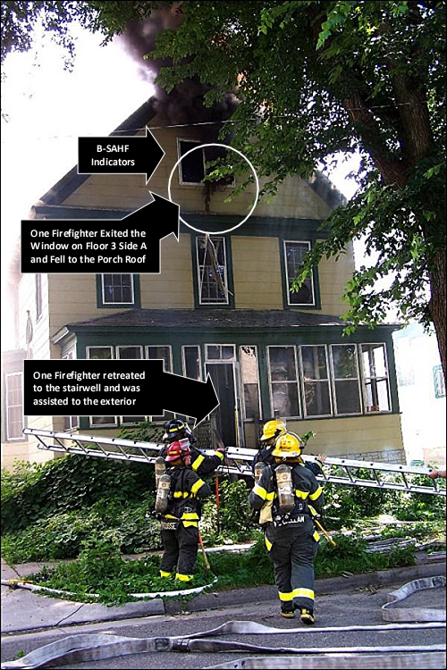
    My last two posts (Hazards Above, Hazards Above: Part 2)examined a series of incidents involving firefighter injuries or near miss incidents involving fires occurring in or extending into void spaces in wood frame, residential structures. Yesterday, two members of the Bridgeport, Connecticut Fire Department lost their lives under similar circumstances.

    Bridgeport, CT LODD

    At 1553 hours on Saturday, July 24, 2010, the Bridgeport, Connecticut Fire Department was dispatched for a residential fire at 41 Elmwood Avenue. First arriving companies found heavy smoke from Floors 2 and 3 of a 2-1/2 story, wood frame, multi-family dwelling. Lieutenant Steven Velazquez and Firefighter Michael Baik were performing a search of the third floor when they transmitted a Mayday. Lieutenant Velazquez and Firefighter Baik were located on Floor 3 by the Rapid Intervention Team (RIT), but were not breathing and in cardiac arrest when removed from the building. CPR was initiated and they were transported to Bridgeport and St. Vincent’s Hospitals where they were pronounced dead.

    More information on this tragic incident will be provided as it becomes available.

    FBI and Ventilation Controlled Fires-the UL Experiments

    As discussed in Hazards Above: Part 2, obvious smoke and air track indicators of a ventilation controlled fire may become diminished as the fire transitions from growth to decay stage. The decay stage ventilation controlled fire may present similar (but not identical) indicators to an incipient or early growth stage fire.

    Underwriters Laboratories (UL) recently conducted a study of the effects of horizontal, natural ventilation on fires in residential structures (see Did You Ever Wonder. The results of this research will be released this fall along with a free on-line training program through UL University. During this research 15 experiments were conducted in two different residential structures. Fuel loading was consistent and the point of origin was a couch in the living room for each of the tests. The variable was the location, size, and sequence of horizontal ventilation. Interestingly, one observation remained remarkably consistent throughout the tests: Diminished smoke and air track indicators as the ventilation controlled fire transitioned from growth to decay stage. This is illustrated by a series of screen captures from video shot from Side A of the one-story structure used in these experiments.

    Figure 1. Early Growth Stage

    Figure 2. Growth Stage (Peak HRR Prior to Ventilation)

    Figure 3. Decay Stage (Reduced HRR)

    Figure 4. Conditions Immediately Following Ventilation (HRR Increasing)

    Another commonality between each of the experiments was a fairly rapid and significant increase in HRR after ventilation was performed. In no case did ventilation (alone) improve conditions at any location or level inside the test buildings. Horizontal, natural ventilation (tactical or unplanned) with a delay in application of water to the seat of the fire will result in worsening conditions.

    Situational Awareness

    As illustrated in Figure 3, lack of obvious indicators can be deceptive. The structure used in the UL tests did not have normal window glazing as this would have resulted in less predictability in the exact location and sequence of ventilation. However, in an actual structure fire, observation of smoke conditions through windows, condensation on window glazing (incipient or early growth stage) and condensed pyrolizate (decay stage), and heat effects on window treatments (e.g., curtains, blinds) can provide important cues related to the stage of fire development and burning regime.

    It is critical to take a holistic approach to observation of fire behavior indicators, to begin this process from the exterior, and to continue this process while operating on the interior.

    Ed Hartin, MS, EFO, MIFIreE, CFO

    Hazards Above: Part 2

    Monday, July 19th, 2010

    My last post, Hazards Above, provided a brief overview of three incidents involving extreme fire behavior in the attic or truss loft void spaces of wood frame dwellings. This post will examine the similarities and differences between these lessons and identify several important considerations when dealing with fires occurring in or extending to void spaces. At the conclusion of Hazards Above, I posed five questions:

    1. What is similar about these incidents and what is different?
    2. Based on the limited information currently available, what phenomena do you think occurred in each of the cases? What leads you to this conclusion?
    3. What indicators might have pointed to the potential for extreme fire behavior in each of these incidents?
    4. How might building construction have influenced fire dynamics and potential for extreme fire behavior in these incidents?
    5. What hazards are presented by fires in attics/truss lofts and what tactics may be safe and effective to mitigate those hazards?

    Similarities and Differences

    The most obvious similarities between these incidents was that the buildings were of wood frame construction, the fire involved or extended to an attic or truss loft void space, and that some type of extreme fire behavior occurred. In two of the incidents firefighters were seriously injured, while in the other firefighters escaped unharmed.

    Given the limited information available from news reports and photos taken after the occurrence of the extreme fire behavior events, it is not possible to definitively identify what types of phenomena were involved in these three incidents. However, it is interesting to speculate and consider what conditions and phenomena could have been involved. It might be useful to examine each of these incidents individually and then to return to examine fire behavior indicators, construction, and hazards presented by these types of incidents.

    Minneapolis, MN

    In the Minneapolis incident the fire occurred in an older home with legacy construction and relatively small void spaces behind the knee walls and above the ceiling on Floor 3. The triggering event for the occurrence of extreme fire behavior is reported to be opening one of the knee walls on Floor 3. As illustrated in Figure 1, the fire appeared to transition quickly to a growth stage fire (evidenced by the dark smoke and bi-directional air track from the windows on Floor 3 Side A. However blast effects on the structure are not visible in the photo and were not reported.

    Figure 1. Minneapolis MN Incident: Conditions on Side A

    Note: Photo by Steve Skar

    Potential Influencing Factors: While detail on this specific incident is limited, it is likely that the fire burning behind the knee wall was ventilation controlled and increased ventilation resulting from opening the void space resulted in an increase in heat release rate (HRR). Potential exists for any compartment fire that progresses beyond the incipient stage to become ventilation controlled. This is particularly true when the fire is burning in a void space.

    Extreme Fire Behavior: While statements by the fire department indicate that opening the knee wall resulted in occurrence of flashover, this is only one possibility. As discussed in The Hazard of Ventilation Controlled Fires and Fuel and Ventilation, increasing ventilation to a ventilation controlled fire will result in increased HRR. Increased HRR can result in a backdraft (if sufficient concentration of gas phase fuel is present), a vent induced flashover, or simply fire gas ignition (such as rollover or a flash fire) without transition to a fully developed fire.

    Harrisonburg, VA

    The Harrisonburg incident involved extreme fire behavior in Exposure D (not the original fire unit). The extreme fire behavior occurred after members had opened the ceiling to check for extension. However, this may or may not have been the precipitating event. As illustrated in Figure 2, as members prepare to exit from the windows on Floor 3 , Side C, flames are visible on the exterior at the gable, but it appears that combustion is limited to the vinyl siding and soffit covering. There are no indicators of a significant fire in Exposure D at the time that the photo was taken. However, it is important to remember that this is a snapshot of conditions at one point in time from a single perspective.

    Figure 2. Harrisonburg, VA Incident: Conditions on Side C

    Note: Photo by Allen Litten

    Potential Influencing Factors: The truss loft was likely divided between units by a 1 hour fire separation (generally constructed of gypsum board over the wood trusses). While providing a limited barrier to fire and smoke spread, it does not generally provide a complete barrier and smoke infiltration is likely. Sufficient smoke accumulation remote from the original fire location can present risk of a smoke explosion (see NIOSH Report 98-03 regarding a smoke explosion in Durango, Colorado restaurant). Alternately, fire extension into the truss loft above an exposure unit can result in ventilation controlled fire conditions, resulting in increased HRR if the void is opened (from above or below).

    Extreme Fire Behavior: Smoke, air track, and flame indicators on Side C indicate that the fire in the truss loft may not have continued to develop past the initial ignition of accumulated smoke (fuel). It is possible that smoke accumulated in the truss loft above Exposure B and was ignited by subsequent extension from the fire unit. Depending on the fuel (smoke)/air mixture when flames extended into the space above Exposure B ignition could have resulted in a smoke explosion or a less violent fire gas ignition such as a flash fire.

    Sandwich, MA

    In the Sandwich incident, the extreme fire behavior occurred shortly after the hose team applied water to the soffit. However, this may or may not have been the precipitating event. As illustrated in Figure 3, the fire transitioned to a fully developed fire (likely due to the delay in suppression as the injured members were cared for). Blast effects on the structure are obvious.

    Figure 3: Sandwich, MA: Conditions on Sides C and D

    Note: Photos by Britt Crosby (http://www.capecodfd.com)

    Potential Influencing Factors: The roof support system in this home appears to have been constructed of larger dimensional lumber (rather than lightweight truss construction). In addition, it is likely that the attic void spaces involved in this incident were large and complex (given the size of the dwelling and complex roof line). It appears that at least part of the home had a cathedral ceiling. Fire burning in the wood framing around the metal chimney would have allowed smoke (fuel) and hot gases to collect in the attic void in advance of fire extension.

    Extreme Fire Behavior: The violence of the explosion (see blast damage to the roof on Side D in Figure 3) points to the potential for ignition of pre-mixed fuel (smoke) and air, resulting in a smoke explosion. However, it is also possible that failure of an interior ceiling (due to water or steam production from water applied through the soffit) could have increased ventilation to a ventilation controlled fire burning in the attic, resulting in a backdraft).

    Fire Behavior Indicators

    The information provided in news reports points to limited indication of potential for extreme fire behavior. One important question for each of us is how we can recognize this potential, even when indicators are subtle or even absent.

    Important! A growth stage fire can present significant smoke and air track indicators, with increasing thickness (optical density), darkening color, and increasing velocity of smoke discharge. However, as discussed in The Hazard of Ventilation Controlled Fires, when the fire becomes ventilation controlled, indicators can diminish to the point where the fire appears to be in the incipient stage. This change in smoke and air track indicators was consistently observed during the full-scale fire tests of the influence of ventilation on fires in single-family homes conducted by UL earlier this year.

    Even with an opening into another compartment or to the exterior of the building, a compartment fire can become ventilation controlled. Consider building factors including potential for fire and smoke extension into void spaces in assessing fire conditions and potential for extreme fire behavior. A ventilation controlled fire or flammable mixture of smoke and air may be present in a void space with limited indication from the exterior or even when working inside the structure.

    Building Construction

    Each of these incidents occurred in a wood frame structure. However, the construction in each case was somewhat different.

    In Minneapolis, the house was likely balloon frame construction with full dimension lumber. As with many other structures with a “half-story”, the space under the pitched roof is framed out with knee walls to provide finished space. This design is not unique to legacy construction and may also be found with room-in-attic trusses. The void space behind the knee wall provides a significant avenue for fire spread. When involved in fire, opening this void space can quickly change fire conditions on the top floor as air reaches the (likely ventilation controlled) fire.

    The incident in Harrisonburg involved a fire in a townhouse with the extreme fire behavior phenomena occurring in an exposure. While not reported, it is extremely likely that the roof support system was comprised of lightweight wood trusses. In addition, there was a reverse gable (possibly on Sides A and C) that provided an additional void. As previously indicated, the truss loft between dwelling units is typically separated by a one-hour rated draft stop. Unlike a fire wall, draft stops do not penetrate the roof and may be compromised by penetrations (after final, pre-occupancy inspection). Installed to code, draft stops slow fire spread, but may not fully stop the spread of smoke (fuel) into the truss lofts above exposures.

    Firefighters in Sandwich were faced with a fire in an extremely large, wood frame dwelling. While the roof appeared to be supported by large dimensional lumber, it is likely that there were large void spaces as a result of the complex roofline. In addition, the framed out space around the metal chimney provided an avenue for fire and smoke spread from the lower level of the home to the attic void space.

    Hazards and Tactics

    Forewarned is forearmed! Awareness of the potential for rapid fire development when opening void spaces is critical. Given this threat, do not open the void unless you have a hoseline in hand (not just nearby).

    Indirect attack can be an effective tactic for fires in void spaces. This can be accomplished by making a limited opening and applying water from a combination nozzle or using a piercing nozzle (which further limits introduction of air into the void).

    If there are hot gases overhead, cool them before pulling the ceiling or opening walls when fire may be in void spaces. Pulses of water fog not only cool the hot gases, but also act as thermal ballast; reducing the potential for ignition should flames extend from the void when it is opened.

    Lastly, react immediately and appropriately when faced with worsening fire conditions. Review my previous posts on Battle Drill (Part 1, Part 2, and Part 3). An immediate tactical withdrawal under the protection of a hoseline is generally safer than emergency window egress (particularly when ladders have not yet been placed to the window).

    Ed Hartin, MS, EFO, MIFireE, CFO