Posts Tagged ‘practical fire dynamics’

Gas Cooling: Part 5

Wednesday, October 6th, 2010

This is the last post in the series examining the science of gas cooling as a fire control tactic. Be forewarned, there is math ahead! I have made an attempt at providing sufficient explanation to allow firefighters, fire officers, and instructors to develop an understanding the scientific concepts underlying this fire control technique. My next post will return to the topic of extreme fire behavior and ventilation with discussion of the most recently released NIOSH report, Death in the Line of Duty 2010-10.

The Mathematical Explanation

Dr. Stefan Särdqvist provides a mathematical explanation of volume changes during smoke/gas cooling In Water and Other Extinguishing Agents (Särdqvist,2002). Stefan’s text includes a graph that illustrates volume changes based on the extent to which the upper layer is cooled and the percentage of the water that is vaporized in the hot gases versus on contact with hot surfaces. As illustrated in Figure 1, the relative volume (expansion or contraction) of the upper layer during gas cooling is dependent on the percentage of water vaporizing as water passes through the hot gases of the upper layer and the percentage of water vaporizing on contact with hot surfaces such as compartment linings.

Figure 1. Volume Changes During Gas Cooling
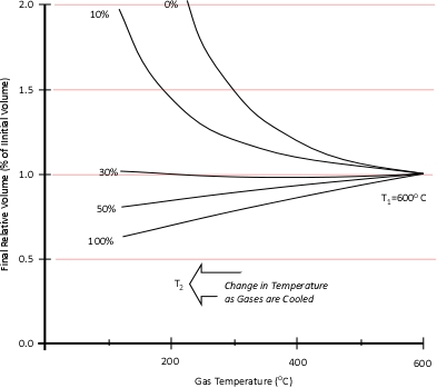
Note: Adapted from Water and Other Extinguishing Agents (p. 155), by Stefan Särdqvist, 2002, Karlstad, Sweden: Räddnings Verket. Copyright 2002 by Räddnings Verket

If 100% of water applied for cooling vaporizes in the upper layer, the total volume of the hot fire gases and steam in the upper layer will be 79% of the original volume of the hot gases alone. If approximately 30% of the cooling water vaporizes in the upper layer and 70% vaporizes on contact with hot surfaces such as compartment linings (e.g., ceiling, walls) the volume of the upper layer will remain the same. However, if less than 30% of the cooling water is vaporized in the upper layer and the remainder is vaporized on contact with hot surfaces, the volume of the upper layer (hot fire gases and steam) will increase.

Understanding why this is the case requires a good understanding of the ideal gas law and a willingness to work through the math. As Greg Gorbett and Jim Pharr observe in the math review chapter of Fire Dynamics (2010), “The term algebra inspires dread in many otherwise competent, confident people” (p. 16).

Gas Cooling and the Ideal Gas Law

Gas Cooling: Part 4, examined the expansion ratio of steam using the Ideal Gas Law, providing a worked example to illustrate how to solve for the change in volume when water is vaporized to steam. As illustrated below, the Ideal Gas Law can also be used to determine relative influences of contraction of the upper layer and expansion of steam during gas cooling.

Before the application of water:

After the application of water:

Where:

P=Pressure (Pa)

V= Volume (m3)

T=Temperature (K)

n=Moles

Ru=Universal Gas Constant (8.3145 J/mol K)

Subscript of 1 refers to initial conditions where the upper layer consists of hot smoke and air

Subscript of 2 refers to conditions at (later) time where the upper layer consists not only to the hot smoke and air, but also to the water applied for cooling (the number of molecules in the upper layer increases, and temperature changes).

Another way of expressing the initial and final conditions using the two gas laws is to set them equal to one another:

Pressure (P) in the fire compartment and adjacent compartments remains relatively constant (due to compartment openings and other leakage). For example, the National Fire Protection Association (NFPA) Standard 92A Standard for Smoke Control Systems Using Barriers and Pressure Differences (2009) specifies a design pressure difference of 24.9 Pa (0.0036 psi) to exclude smoke from a protected area (such as a stairwell) in a non-sprinklered building with 2.7 m (9’) ceilings. As atmospheric pressure is 102325 Pa (14.7 psi) the pressure difference, while significant enough to influence smoke movement is actually quite small in most cases. Given that pressure is relatively constant and the Universal Gas Constant (Ru) is the same for all ideal gases, these factors will have the same effect on initial and final conditions (allowing both Ru and P to be factored out of the ideal gas equations used to determine changes in upper layer volume.

After factoring out Ru and P, the relationship between the upper layer volume before and after application of water is as follows:

Lots Going On!

When water is applied to cool the upper layer, there is quite a bit going on. Energy is transferred from the upper layer to the water, lowering the temperature of the upper layer and raising the temperature of the water to its boiling point, vaporizing the water, and raising the temperature of the resulting steam. As the absolute temperature of the upper layer is reduced, its volume is proportionally reduced. However, as water is vaporized at its boiling point and the absolute temperature of the resulting steam is increased its volume increases. The important question is where was the water vaporized? Water vaporized in the upper layer, absorbed energy from the hot gases, lowering their absolute temperature. However, water that passes through the hot gas layer and vaporizes on contact with hot surfaces such as compartment linings (e.g., ceiling, walls) did not absorb significant energy from the upper layer and did not significantly reduce the temperature of the upper layer. Steam produced as a result of water vaporizing on contact with hot surfaces can absorb energy from the upper layer, but this has far less impact than water vaporized within the upper layer due to the large difference between the specific heat of steam and the latent heat of vaporization of water.

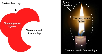
While some energy is lost as a result of convection of hot gases out compartment openings and conduction through compartment linings and other structural materials, these factors are not considered in this analysis of the effect of gas cooling. In this analysis the compartment defines the bounds of the thermodynamic system and the gas cooling process is considered to be adiabatic (no energy is gained or lost by the system).

Step by Step

I have made a few revisions to the explanation of gas cooling in Water and Other Extinguishing Agents (Särdqvist,2002), most significant of which is inclusion of the energy required to raise the temperature of the water applied for cooling to its boiling point (100o C). While the amount of energy is not large, this addition provides a more complete picture of the process involved in gas cooling. Other changes include consistent use of J/mol as units for specific heat and latent heat of vaporization, and minor variations in notation.

The mathematical explanation of gas cooling starts out in the same place as the concrete example provided in Gas Cooling Parts 1 and 2, determining the energy that must be transferred from the upper layer to water applied for cooling in order to achieve a specific reduction in temperature and the amount of water required to accomplish this. However, unlike an example using a specific compartment in which the units for specific heat and latent heat of vaporization were J/kg, the mathematical explanation uses J/mol (the reason for this will become clear as we dig a bit deeper).

The relationship between J/mol and kJ/kg as units of measure for specific heat and latent heat of vaporization is fairly straightforward as illustrated below:

The following equation explains the energy balance between hot gases in the upper layer and water applied for cooling. At first glance, this equation seems extremely complex, but if each segment is examined individually, it is fairly straightforward.

Where

Cp,g=Specific heat capacity of fire gases/smoke (approximately the same as air, 33.2 J/mol K at 1000 K).

Cp,st=Specific heat capacity of steam (41.2 J/mol K at 1000 K)

Cp,w=Specific heat capacity of water (76.663 J/mol K at 215.15 K)

LV,w=Latent heat of vaporization of water 40,680 J/mol

Tu=Temperature of the upper layer (K)

Tw=Temperature of water (K)

n=Moles

Subscript of 1 refers to initial conditions

Subscript of 2 refers to conditions at (later) time 2

First examine the left side of the equation which deals with the hot gases in the upper layer.

The left side of the equation determines the energy that must be transferred from the hot gases in the upper layer in order to result in a specific reduction in temperature. As this example does not deal with a specific compartment, the mass of the upper layer is unknown. A challenge resolved through the use of moles to define the amount of hot fire gases present in the upper layer. Remember that moles are a measure of the number of molecules present.

Multiplying the molar specific heat of smoke (Cp,g) in J/mol K by the number of moles (n) determines the energy that must be transferred from the upper layer to change its temperature 1 K. Multiplying that value by the change in absolute temperature (T1-T2) determines the total energy that must be transferred to achieve the specified change in absolute temperature.

Now examine the right side of the equation which deals with the water applied for cooling:

The right side of the equation determines the energy that must be transferred to the water applied for cooling in order to increase the temperature of the water (as steam) by the same extent as the reduction in upper layer temperature.

The first step is to determine the amount of water applied (remember the assumption that all water applied is vaporized either in the gas layer or on contact with surfaces). This is accomplished by subtracting the amount of hot gases in the upper layer (in Moles) from the amount of hot gases, and steam in the upper layer after cooling the gases (n2 – n1).

When vaporized in the upper layer, energy is transferred from the hot gases in the upper layer to 1) raise the temperature of the water to its boiling point of 373.15 K (100o C), 2) to change its state from liquid phase to gas phase, and 3) to raise the temperature of the steam until reaching equilibrium (hot gases and steam are at the same temperature). When water is vaporized on contact with a hot surface, it did not absorb significant energy while traveling through the hot gasses of the upper layer. The energy necessary to raise the temperature of the water to its boiling point and vaporize it is absorbed from the surface. Steam produced in this manner will also absorb energy from the hot gases of the upper layer (but the process of increasing the temperature of the water in liquid form and vaporization did not take significant energy from the hot gasses of the upper layer).

Figure 2. Gas Versus Surface Cooling
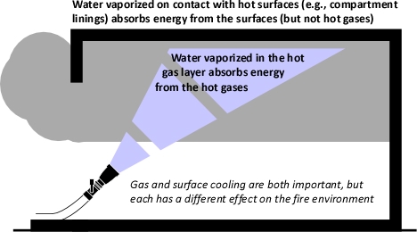
As water that is vaporized in the upper layer absorbs energy from the hot gases to raise its temperature to boiling and vaporize.

The temperature increase required for water to reach its boiling point is determined by subtracting the initial temperature of the water (Tw,1) from its boiling point of 373.15 K. The increase in the temperature of the water in liquid form is multiplied by the specific heat of water (Cp,w) to calculate the total energy required for this temperature increase (Cp,w (373.15- Tw,1)).

The latent heat of vaporization (LV,w) is added to the energy required to raise the temperature of the water from Tw1 to its boiling point of 373.15 K (100o C).

After water is vaporized (either while traveling through the upper layer or on contact with a hot surface) it continues to absorb energy from the upper layer until the temperature of the steam and the hot gases in the upper layer reach the same temperature and are in thermal equilibrium. The specific heat of steam (Cp,w) is multiplied by the difference between 373.15 K (100o C) and the final temperature of the upper layer (Tu2). This determines the energy required for the steam and the hot gases in the upper layer to reach thermal equilibrium ( ).

As with the calculations examining the smoke and hot gases in the upper layer, moles are a measure of the amount of water applied for cooling. As the thermodynamic system of the compartment is being treated as adiabatic (no energy leaves the system, it is simply transferred between the hot gases of the upper layer and the water applied for cooling), the left and right sides of the equation must be equal.

Solving for n, this equation may also be written:

Given that:

The left side of the equation can be simplified to solve for the amount of molecules in the upper layer before cooling (n1) and after application of water (n2) as follows:

Solving for n allows the energy exchange equation to be combined with the two ideal gas laws used to describe changes in volume associated with gas cooling.

As the energy exchange equation is equal to the initial amount of gas molecules in the upper layer before gas cooling divided by the amount of gas molecules in the upper layer after the application of water, the energy balance equation can be inserted in the ideal gas law in place of the amount of molecules (n1 and n2) as illustrated below:

This formula looks quite complex, but in actuality most of the values are constants such as the specific heat of water (Cp,w), latent heat of vaporization of water (LVw), and specific heat of steam (Cp,st). After plugging in these constants, the only variables on the right side of the equation are the temperature of the upper layer before and after cooling and the percentage of water vaporized in the upper layer.

The volume of the upper layer after cooling divided by the volume of the upper layer before cooling is the percentage change in volume of the upper layer.

Worked Examples

While explaining the equations is important, there is nothing quite so useful in developing understanding as actual worked examples. In each of these examples, the initial upper layer temperature is 773.15 K (500o C), the initial temperature of the cooling water is 293.15 K (20o C) and the final temperature of the upper layer is 473.15 K (200o C).

Example 1: All (100%) of the water applied for cooling is vaporized in the upper layer.

In this example where all of the water applied for cooling is vaporized in the upper layer, the volume of the upper layer is reduced by 27% and the lower boundary of the upper layer would rise. This illustrates the ideal (but likely not achievable) application of gas cooling to reduce temperature and raise the lower boundary of the upper layer.

Example 2: None (0%) the water applied for cooling is vaporized in the upper layer; all of it is vaporized on contact with hot compartment linings or other surfaces.

In this example where none of the water applied for cooling is vaporized in the upper layer, but vaporizes on contact with hot surfaces, the volume of the upper layer would double. If the upper layer filled more than half the volume of the compartment, the upper layer would then fill the entire compartment with hot gases and steam at 473.15 K (200o C), providing an untenable environment for both firefighters and trapped occupants. This is why an indirect attack is not used from inside the compartment or in compartments where there may be savable victims.

Example 3: One third (33.3%) of the water applied for cooling vaporizes in the upper layer and the remainder (66.6%) is vaporized on contact with hot compartment linings or other surfaces.

In this example, the volume of the upper layer is unchanged, but considerably cooler than before the application of water. If firefighters had adequate working area below the upper layer before applying cooling water, this would be unchanged, but the temperature of the gases overhead would be considerably reduced. With good technique and an appropriate flow rate, more than 33.3% of the water applied for cooling can be vaporized in the upper layer, providing practical results somewhere between a 3% (Example 3) and 27% (Example 1) reduction in the volume of the upper layer. However, it is important to remember that the fireground is much more dynamic than the simple analysis presented in this post.

Different Parts of the Elephant

Firefighter’s perspectives on the use of water fog for interior structural firefighting can be compared to the Indian fable of The Six Blind Men and the Elephant (Saxe, 1963). In this fable, the six men tried to determine what an elephant was. As none of the men could see, they used their sense of touch. However, each grasped a different part of the elephant. One touched the side and thought an elephant was like a wall, another the trunk and thought an elephant was like a snake, and so forth. What you believe may be limited by your point of observation.

Many firefighters in the United States find it hard to believe that the volume of the upper layer can be reduced and the bottom of the upper layer raised by application of water. This is inconsistent with their experiences in the field. The explanation provided in this post illustrates how this is possible. If flow rate and application technique used result in more than 70% of cooling water vaporizing on contact with hot surfaces, the upper layer will increase in volume and the level of the hot gas layer in a confined area such as a compartment will become lower (consistent with many firefighters experience when using water fog for interior structural firefighting). However, this does not have to be the case. Where the water is vaporized and the resulting effects are dependent on application technique, flow rate, and duration of application!

I would like to extend a great deal of thanks to Stefan Särdqvist for providing the basis for this explanation and to Lieutenant Felipe Baeza Lehnert of Valdivia (Chile) Fire Department Company 1 (Germania) for his patience in helping me sort though the math.

Ed Hartin, MS, EFO, MIFireE, CFO

References

National Fire Protection Association (NFPA). (2009). Standard 92A Standard for Smoke Control Systems Using Barriers and Pressure Differences. Quincy, MA: Author.

Saxe, J. (1963). The blind men and the elephant. New York: McGraw-Hill

Särdqvist, S. (2002) Water and other extinguishing agents. Karlstad, Sweden: Räddnings Verket

Gas Cooling: Part 4

Sunday, September 12th, 2010

Reading the Fire

Before returning to discussion of the science underlying gas cooling as a fire control technique, I wanted to share a video of an industrial fire in Maidencreek Township, Pennsylvania that provides an excellent illustration of smoke and air track indicators. Watch the first minute (1:00) of the video and answer the following questions:

  • Consider how you would read the smoke and air track indicators (particularly the level of the neutral plane and velocity) if this was a single family dwelling. How is air track indicators are different in a large building (with multiple ventilation openings) such as was the case in this incident?
  • What stage of development (incipient, growth, fully developed, or decay) and burning regime (fuel or ventilation controlled) is this fire in?
  • Watch the remainder of the video and examine the effectiveness of the master stream application? Are the streams effective? Why or why not? What could be done to increase the effectiveness of application?

For additional information on reading the fire, see the following posts:

Gas Laws

Paraphrasing Albert Einstein, British science writer Simon Singh stated that, “Science has nothing to do with common sense. Common sense is a set of prejudices” (Capps, 2010, p. 115). One of the challenges faced by firefighters engaging with the science of their craft is the common sense understanding of the fire environment and firefighting practices. This post continues examination of gas cooling as a fire control technique, by peeling off a few more layers and digging deeper into the underlying science related to the behavior of gases.

Readers who have worked through Gas Cooling Part 1, Part 2, and Part 3 have a reasonable idea how a small volume of water can reduce the temperature of the upper layer in a compartment and also reduce the volume of the upper layer (raising the level of the lower boundary of the layer). In addition, readers are likely to also understand the limitations of the simple explanation provided in prior posts.

In Water and Other Extinguishing Agents (Särdqvist,2002), Dr. Stefan Särdqvist provides a fairly detailed explanation of volume changes during smoke cooling and examines how the percentage of water vaporizing in the upper layer influences these changes. Understanding Stefan’s explanation requires a good understanding of the ideal gas law and a willingness to work through the math.

Gas Laws

The introduction to the gas laws and overview of Charles’s Law was provided in Gas Cooling: Part 3. This content has been repeated in this post, to save you from going back to the previous post.

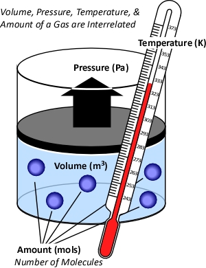
While gases have different characteristics and properties, the behavior of gases can be described in general terms using the ideal gas law. This physical law describes the relationship between absolute temperature, volume, and pressure of a given amount of an ideal gas.

Figure 1. Temperature, Volume, Pressure & Amount

The concept of an ideal gas is based on the following assumptions:

  • Gases consist of molecules in random motion
  • The volume of the molecules is negligible in comparison to the total volume occupied by the gas
  • Intermolecular forces (i.e., attractive forces between molecules) are negligible
  • Pressure is the result of gas molecules colliding with the walls of its container

The ideal gas law is actually a synthesis of several other physical laws that each describes a single characteristic of the behavior of gases in a closed system (enclosed in some type of container).

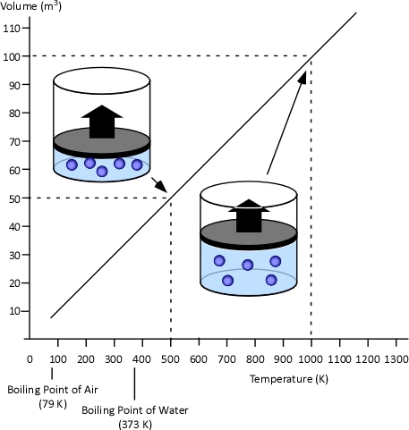
Charles’s Law: In the 1780s, French scientist Jacques Charles studied the effect of temperature on a sample of gas at a constant pressure. Charles found that as the gas was heated, the volume increased. As the gas was cooled, the volume decreased. This finding gave rise to Charles’s Law which states that at a constant pressure the volume of a given amount (mass or number of molecules) of an ideal gas increases or decreases in direct proportion with its absolute (thermodynamic) temperature. The symbol  is used to express a proportional relationship (much the same as = is used to express equality), so this relationship can be expressed as:

Where:

V=Volume

T=Temperature

When two values (such as volume and temperature in Charles’s Law) are proportional, one is a consistent multiple of the other. For example If one value was consistently eight times the other, the values would also be proportional. In the case of Charles’s Law when the absolute temperature of a gas doubles, the pressure doubles. Figure 2 illustrates the relationship between absolute temperature in Kelvins (K) and volume in cubic millimeters (mm3).

Figure 2. Charles’s Law

This relationship can also be stated using the following equation:

Where

V=Volume

T=Temperature

Subscript of 1 refers to initial conditions

Subscript of 2 refers to final conditions

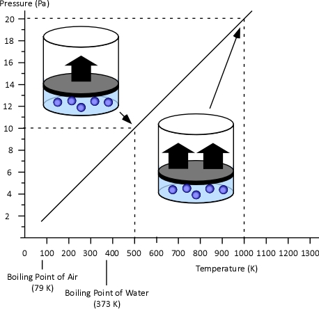
Gay-Lussac’s Law: When Jacques Charles discovered the relationship between temperature and volume, he also discovered a similar relationship between temperature and pressure. However, Charles never published this discovery. Charles’s work on temperature and pressure was recreated by French chemist Joseph-Louis Gay-Lussac. Gay Lussac’s Law states that if the volume of an ideal gas is held constant, the pressure of a given amount (mass or number of molecules) of an ideal gas increases or decreases proportionally with its absolute temperature. As with Charles’s Law, Gay-Lussac’s law can be expressed mathematically as:

Where

V=Volume

P=Pressure

Figure 3. Gay-Lussac’s Law

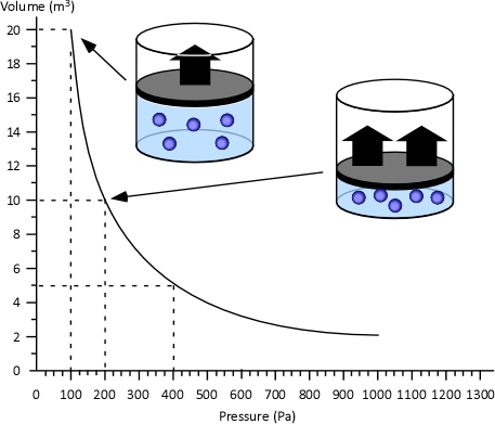
Boyle’s Law: in the 1660s, Irish physicist Robert Boyle studied the relationship of pressure and volume of gases. Boyle discovered that as pressure on a gas was increased, its volume decreased. Boyle’s Law states that if the temperature of an ideal gas is held constant, the pressure and volume of a given amount (mass or number of molecules) of an ideal gas are inversely proportional, as pressure increases, the volume occupied by the gas decreases. Boyle’s Law can be expressed mathematically as:

Where:

V=Volume

P=Pressure

Figure 4. Boyle’s Law

General Gas Law: The General Gas Law simply integrates Charles’s, Gay-Lussac’s, and Boyle’s Laws to state that the volume of an ideal gas is proportional to the amount (number of molecules) and absolute temperature and inversely proportional to pressure. The General Gas Law can be expressed mathematically as:

Where:

V=Volume

n=Mole (mol)

T=Temperature

P=Pressure

The General Gas Law defines the amount of gas in terms of the number of molecules, measured in moles (which has nothing to do with the animal having the same name).

Mole: While related to Avogadro’s Law, the term mole as a unit of measure was conceived by German chemist Wilhelm Ostwald in 1893. Unlike liters or grams, a mole is not a unit of volume or mass, but a counting unit. A mole is defined as the quantity of anything that has the same number of particles found in 12 grams of carbon-12. As atoms and molecules are extremely small, a mole is a large number of molecules. Specifically a mole contains 602,510,000,000,000,000,000,000 (more commonly written 6.0251 x 10²³ in scientific notation) molecules of a substance. The number of moles of a substance is denoted by the letter n. In SI units, a kilogram mole (Kmol) is often used instead of the mole. A Kmol is 1000 mol or 6.0251 x 1026 molecules of a substance.

It may seem that using the mole to measure an amount of a substance makes this more complicated. After all, why not use a measure of volume such as liters or cubic meters or mass such as grams or kilograms? Chemical formula (such as H2O for water) describes the makeup of a chemical compound in terms of the numbers of atoms of each element comprising a single molecule of the substance.

While not a unit of mass, moles can be related to mass (just as you can determine the mass of a dozen eggs of a given size, by multiplying the mass of one of the eggs by 12).

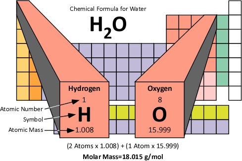
Molar Mass: The molar mass of a compound is the mass of 1.0 moles of the substance in grams. Molar mass is determined by the sum of the standard atomic weights of the atoms which form the compound multiplied by the molar mass constant (Mu) of 1 g/mol. Figure 5 illustrates how the molar mass of water is calculated.

Figure 5. Molar Mass of Water

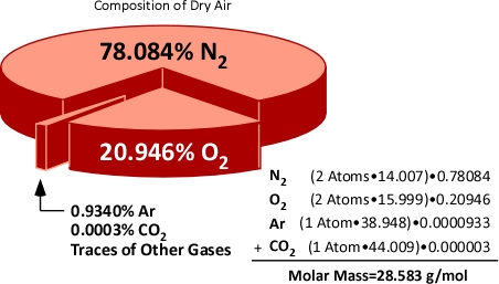
Molar mass can also be calculated for mixtures of substances. When dealing with mixtures, the molar mass of each constituent is calculated and applied proportionately on the basis of the percentage of that substance in the mixture. For example air is comprised of 78% Nitrogen, 21% Oxygen, and 1% of other gases such as Argon (Ar) and Carbon Dioxide (CO2). Nitrogen (N2) and Oxygen (O2) molecules are each comprised of two atoms (and are referred to as diatomic molecules). This means that the molar mass of Nitrogen and Oxygen molecules is twice the atomic mass.

Figure 6. Molar Mass of Air

Hopefully how the concepts of the mole and molar mass can be applied will become clear after examining the expansion of water when turned to steam and application of the gas laws to integrate steam expansion and changes in volume of the upper layer during gas cooling under a variety of circumstances.

Avogadro’s Law: In 1811, Italian physicist and mathematician Amedeo Avogadro published a theory regarding the relationship of the number of molecules in a gas if temperature, pressure, and volume are held constant. Avogadro’s Law states that samples of ideal gasses, at the same absolute temperature, pressure and volume, contain the same number of molecules regardless of their chemical nature and physical properties. More specifically, at a temperature of 273 K (0oC) and absolute pressure of 101300 Pa, 22.41 L (0.001 m3) of an ideal gas contains 6.0251 x 10²³ molecules (1.0 mol)

Ideal Gas Law: This gas law integrates Avogadro’s law with the Combined Gas Law. If the number of molecules in a specific volume of an ideal gas at a consistent temperature and pressure (273 K and 101300 Pa) is always the same, then the proportional relationship between pressure, volume, temperature, and amount can be defined as having a constant value (Universal Gas Constant).

Where:

P=Pressure (Pa)

V= Volume (m3)

T=Temperature (K)

n=Moles

Ru=Universal Gas Constant (8.3145 J/mol K)

Universal Gas Constant (Ru): This physical constant identifies the internal kinetic energy per mole of an ideal gas for each Kelvin of temperature (J/mol K). As it is universal this constant is the same for all gases that demonstrate the properties of an ideal gas.

If the pressure, volume, and temperature of an ideal gas can be observed and Avogadro’s Law is accepted as being true (making the amount of gas also known), the value of the Universal Gas Constant can be determined empirically (based on observation) by solving the ideal gas law equation for Ru.

Where:

V=Volume

Ru=Universal Gas Constant

n=Moles

T=Temperature

P=Pressure

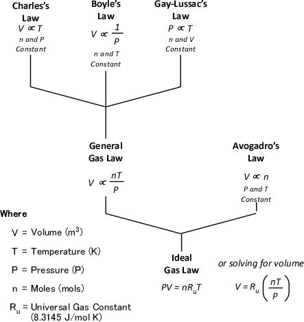
Figure 7 illustrates each of the gas laws and how they are integrated into the Ideal Gas Law.

Figure 7. Gas Laws

Application-Steam Expansion

As stated in Gas Cooling: Part 3, the 5th Edition of the Essentials of Firefighting (IFSTA, 2008) states that the volume of water expands 1700 times when it is converted to steam at 100o C (212o F). However, this information is presented as a fact to be memorized and no explanation is provided as to why this is the case or that if temperature is increased further, that the volume of steam will continue to expand. In the previous post, I asked the reader to accept this assumption with assurance that an explanation would follow. Application of the ideal gas law to expansion of steam provides an excellent opportunity to exercise your understanding of the gas laws and other scientific concepts presented in this post.

What we know:

  • Molecular Mass of Water: 18 g/mol
  • Boiling Point of Water at Atmospheric Pressure: 100o C (373.15 K)
  • Density of Water at 20o C (293.15 K): 1000000 g/m3
  • Atmospheric Pressure: 101325 Pa
  • Ideal Gas Constant (Ru): 8.3145 J/mol K

What we need to find out:

  1. What is the volume of 1 mole of steam
  2. What is the density (mass per unit volume) of steam at 100o C
  3. What is the ratio between the density of water and the density of steam at 100o C

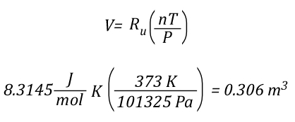
The volume of 1 mole of pure steam can be calculated by solving the ideal gas equation for V.

As 1 mole of water (in the liquid or gaseous phase) contains the same number of molecules, it’s molar mass will be the same. 1 mole of water has a mass of 18 grams. Density is calculated by dividing mass by volume, so the density of steam at 100o C can be calculated as follows:

Dividing the density of water by the density of steam at 100o C determines the expansion ratio when a specific mass of water is vaporized into steam at this temperature.

This means that if a specific mass of water is vaporized into steam at 100o C, its volume will expand 1700 times. So the 5th Edition of the Essentials of Firefighting (IFSTA, 2008) is correct, but now you know why. However, what would happen if the steam continued to absorb energy from the upper layer and its temperature increased from 100o C to 300o C, the mass of the steam would remain the same, but what would happen to the volume? You can use the Ideal Gas Law to solve this question as well.

The Next Step

Just as the Ideal Gas Law can be used to determine the expiation ratio of steam, it can also be used to calculate contraction of the upper layer as it is cooled. The next post will examine how Dr. Stefan Särdqvist integrates these two calculations to determine changes in the volume of the upper layer under a variety of conditions.

New Book

Greg Gorbett and Jim Phar of Eastern Kentucky University (EKU) have written a textbook titled Fire Dynamics focused on meeting the Fire and Emergency Services Higher Education (FESHE) curriculum requirements for Fire Behavior and Combustion. I just received my copy and at first glance it appears to be an excellent work (as I would expect from these outstanding fire service educators). One useful feature of the text is a basic review of math, chemistry, and physics as it relates to the content of the course. I will be dong a more detailed review of the book in a subsequent post, but wanted to give readers of the CFBT-US Blog a heads up that it had been released.

Ed Hartin, MS, EFO, MIFireE, CFO

References

International Fire Service Training Association (IFSTA). (2008). Essentials of firefighting (5th ed). Stillwater, OK: Fire Protection Publications.

Särdqvist, S. (2002) Water and other extinguishing agents. Karlstad, Sweden: Räddnings Verket

Gas Cooling: Part 3

Sunday, September 5th, 2010

The first post in this series, Gas Cooling, began the process of providing a conceptual explanation of the fire control technique of gas cooling. As previously discussed, gas cooling reduces the hazards presented by the upper layer in a compartment fire by cooling hot gases and reducing the potential that they will ignite. Water is an effective fire control agent for this purpose because a tremendous amount of energy is required to raise its temperature and vaporize it at its boiling point.

Gas Cooling: Part 2 identified the amount of water that is theoretically necessary to cool the upper layer of a compartment containing 40 m3 (4 m wide  x 5 m long x 2 m deep) from 500o C (932o F) to 100o C (212o F). In addition, this post identified practical limitations with the efficiency of typical combination nozzles used and determined the duration of application necessary to cool the upper layer to 100o C (212o F) at different flow rates.

This raises the question, what would happen if you didn’t apply sufficient water to cool the upper layer to 100o C (212o F)?

What If?

Steam continues to absorb energy if its temperature is increased above 100o C (212o F). Some firefighters are under the impression that you cannot have steam at a temperature above 100o C (212o F) at normal atmospheric pressure. This is incorrect. Water (in liquid form) will not increase above 100o C (212o F) as this is it’s boiling point at normal atmospheric pressure, but steam acts as any other substance in the gaseous form and can increase in temperature beyond that which it changed phase from liquid to gas.

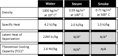
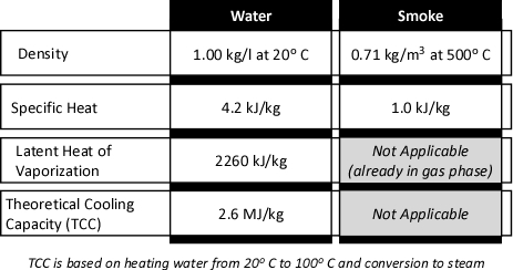
Figure 1. Properties of Water, Steam, & Smoke

Properties of Water, Steam, and Smoke

1 100 kg/M3 =1 kg/l

2 Not applicable as smoke and steam are in the gas phase

3 TCC is based on heating water from 20o C to 100o C and conversion to steam

4 Steam will continue to absorb energy until reaching temperature equilibrium

As illustrated in Figure 1, a kilogram of steam (slightly under 1.69 m3 at 100o C) will absorb 2.0 kJ of energy for each oC that the temperature of the steam is increased. The temperature of steam will continue to increase as long as the surrounding gases and/or surfaces that it is in contact with are of higher temperature. This process will continue until the steam, gases, and surfaces that the steam is in contact with reach equilibrium (i.e., the same temperature).

So even if insufficient water is applied to lower the temperature of the upper layer to 100o C (as described in Gas Cooling: Part 2 [LINK]), the combined effects of heating and vaporizing the water (the major cooling mechanism) and heating the steam produced to a temperature higher than 100o C (212o F), can have a significant cooling effect. This effect is often sufficient to extinguish flames in the upper layer and slow or reduce pyrolysis caused by heating of fuel packages due to radiative and conductive heat transfer from the flames and hot gases in the upper layer.

Gas Laws

When water as a liquid is vaporized to form steam, it expands and becomes less dense. Fire service texts such as the 5th Edition of the Essentials of Firefighting (IFSTA, 2008) commonly state that the volume of water expands 1700 times when it is converted to steam at 100o C (212o F). These texts state this as a fact to be memorized, but do not explain why this is the case or that if temperature is increased further, that the volume of steam will continue to expand. While having a number of different characteristics as illustrated in Figure 1, steam and smoke are both in the gas phase, they behave somewhat similarly. In chemistry and physics, the behavior of gases is described by a number of physical laws collectively described as the gas laws. Understanding the gas laws provides an explanation of why smoke and the steam produced during firefighting operations behave the way in which they do.

While gases have different characteristics and properties, behavior of gases can be described in general terms using the ideal gas law. This physical law describes the relationship between absolute temperature, volume, and pressure of a given amount of an ideal gas.

Figure 2. Temperature, Volume, Pressure & Amount

The concept of an ideal gas is based on the following assumptions:

  • Gases consist of molecules in random motion
  • The volume of the molecules is negligible in comparison to the total volume occupied by the gas
  • Intermolecular forces (i.e., attractive forces between molecules) are negligible
  • Pressure is the result of gas molecules colliding with the walls of its container

The ideal gas law is actually a synthesis of several other physical laws that each describes a single characteristic of the behavior of gases in a closed system (enclosed in some type of container). Of these gas laws, Charles’s Law provides the simplest explanation of the phenomena that occur during gas cooling.

Charles’s Law: In the 1780s, French scientist Jacques Charles studied the effect of temperature on a sample of gas at a constant pressure. Charles found that as the gas was heated, the volume increased. As the gas was cooled, the volume decreased. This finding gave rise to Charles’s Law which states that at a constant pressure the volume of a given amount (mass or number of molecules) of an ideal gas increases or decreases in direct proportion with its absolute (thermodynamic) temperature. The symbol  is used to express a proportional relationship (much the same as = is used to express equality), so this relationship can be expressed as:

Where:

V=Volume

T=Temperature

When two values (such as volume and temperature in Charles’s Law) are proportional, one is a consistent multiple of the other. For example If one value was consistently eight times the other, the values would also be proportional. In the case of Charles’s Law when the absolute temperature of a gas doubles, the pressure doubles. Figure 3 illustrates the relationship between absolute temperature in Kelvins (K) and volume in cubic millimeters (mm3).

Figure 3. Charles’s Law

This relationship can also be stated using the following equation:

Where

V=Volume

T=Temperature

Subscript of 1 refers to initial conditions

Subscript of 2 refers to final conditions

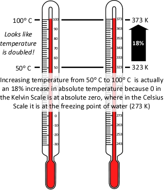
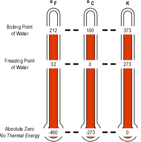
It is important to remember that absolute temperature is measured in Kelvins (K), not degrees Celsius or Fahrenheit, because the Kelvin scale places the zero point at absolute zero, so that doubling the temperature in K, is actually doubling the temperature. As illustrated in Figure 4, the same does not hold true when using the Celsius scale (the Fahrenheit scale presents the same problem).

Figure 4. Absolute Temperature

Application of Charles’s Law provides a simple approach to examining the question of why application of water into the upper layer does not necessarily result in an increase to upper layer volume (by adding steam) and increasing its thickness (with the bottom of the layer moving closer to the floor). This requires the assumption that while the higher temperature inside the fire compartment results in increased pressure, this increase is fairly small and does not have an appreciable outcome on volume changes during gas cooling.

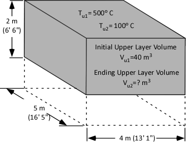
As a first step in answering the question, consider what is known at this point (as illustrated in Figure 5):

  • The initial volume of the upper layer (Vu1) is 40 m3.
  • The initial temperature of the upper layer (Tu1) is 500o C (932o F)
  • The ending temperature of the upper layer (Tu2) is 100o C (212o F)

The answer we are in search of is the ending volume of the upper layer (Vu2), the volume of fire gases (Vfg) plus the volume of steam produced (Vst) during application of water for gas cooling.

Figure 5. Compartment Temperature and Volume

Expanding Steam

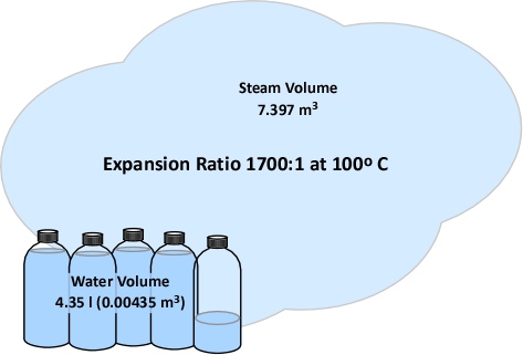
As discussed in Gas Cooling: Part 2 [LINK], 4.35 kg (4.35 l) of water must be vaporized in the upper layer in order to lower the temperature to 100o C (212o F). The volume of water in liters must be converted to cubic meters (the same units of measure used for the volume of the compartment and upper layer). A liter is 0.001 m3, so 4.35 l equals 0.00435 m3. For now, we will accept that conversion of water to steam results in a 1700:1 expansion ratio (a later post in this series will explain why). With an expansion ratio of 1700:1, 0.00435 m3 of water expands to 7.395 m3 of steam at 100o C (212o F) (see Figure 6)

Figure 6. Expansion of Steam at 100o F

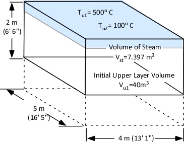
Figure 7 illustrates the volume of steam produced when 4.35 l of water is vaporized in the upper layer of the example compartment relative to the initial volume of the upper layer.

Figure 7. Steam Expansion in a Compartment

Contracting Upper Layer

Why doesn’t the 7.397 m3 of steam that results from vaporization of the 4.35 liters of water applied for gas cooling simply increase the volume of the upper layer by 7.397 m3? Charles’s law provides the key. Charles’s Law indicates that as a gas is heated its volume will increase in direct proportion to the increase in its absolute temperature. However, the reverse is also true. The volume of a gas will decrease in direct proportion to the decrease in its absolute temperature.

Cooling the upper layer from 500o C (932o F) to 100o C (212o F) results in a 52% decrease in absolute temperature from 773 K to 373 K. The volume of the upper layer which was initially 40 m3 is reduced in direct proportion to the reduction in absolute temperature.

The volume of the upper layer (fire gases) after cooling from 500o C (932o F) to 100o C (212o F) can be calculated by solving for Vu2:

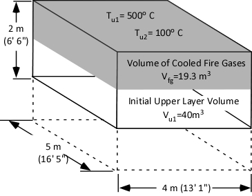
Reduction in temperature from 500o C (932o F) to 100o C (212o F) results in reduction of the volume of fire gases from 40m3 to 19.3 m3 as illustrated in Figure 8.

Figure 8. Contraction of the Upper Layer

Putting it All Together

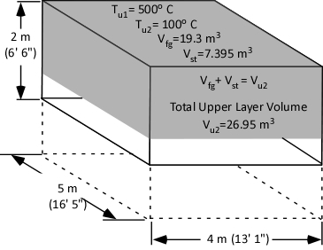
If the water applied to cool the upper layer expands to form 7.395 m3 of steam and the final volume of the cooled upper layer is 19.3 m3, the total upper layer volume is 26.95 m3.

Figure 8. Total Upper Layer Volume

<

Dividing the Total Upper Layer Volume (Vu2) of 26.95 m3 by the area of the compartment (20 m2) determines the depth of the upper layer as being 1.347 m. Therefore, cooling the upper layer from 500o C (932o F) to 100o (212o F) C will cause the bottom of the upper layer to rise 0.6525 m (2.1’).

The Short Answer

The following points summarize the last three posts dealing with gas cooling as a fire control technique:

  • The volume of water required to cool the upper layer is quite small due to its specific heat and latent heat of vaporization in its liquid form and the specific heat of steam.
  • The expansion ratio of steam at 100o C (212o F) is 1700:1, but as the volume of water used to cool the upper layer is small, the expanded volume is still relatively small (in comparison to the contraction of the upper layer).
  • In the process of reaching equilibrium, the temperature of the upper layer is reduced to a greater extent than the temperature of the water increases due to the cooling capacity of the water and the relatively low specific heat of fire gases and air.
  • The large temperature drop in the upper layer results in a proportional reduction in volume (which works out be greater than the increase in volume resulting from the expansion of steam from water vaporized in the hot gas layer for cooling).

Based on each of these factors, a small amount of water can cool the upper layer and reduce its volume, resulting in the lower boundary of the upper layer rising as its depth decreases.

A Few Little Wrinkles!

The preceding example may conflict with your personal experience. Many of us have been in a hot, smoke filled compartment and had steam and smoke bank down on top of us after application of water. Why might this be the case?

The outcome of the preceding example depends on all of the water being vaporized while traveling through the upper layer. In this case, energy to vaporize the water is transferred from the hot gases in the upper layer, cooling the layer and causing it to contract. If the water passes through the upper layer without vaporizing, the temperature of the upper layer is not reduced and it does not contract. Water vaporizing on contact with hot compartment linings results in the steam produced being added to the volume of the upper layer. This steam cools the upper layer to some degree, but far less than using the energy of the hot gases to vaporize the water as it passes through the upper layer (compare the specific heat of steam to the specific heat and latent heat of vaporization of water in Figure 1).

When applying water fog into the upper layer, some of the water vaporizes as it travels through the hot gases and some reaches the compartment linings. Determining changes in the volume of the upper layer under these conditions is a bit more complex and requires a deeper examination of the gas laws.

Continuing the Discussion

The next post in this series will examine the other gas laws that lead to the development to the Ideal Gas Law and how this law can be used to answer questions about changes in upper layer volume as a result of gas cooling under a variety of different conditions.

Spanish Translation of Effective and Efficient Fire Streams

Thanks to Firefighters Tomá Ricci and Martín Comesaña from San Martín de Los Andes, Argentina for translating the series of posts on Fire Stream Effectiveness and Efficiency into Spanish. They can be downloaded in PDF format:

Ed Hartin, MS, EFO, MIFireE, CFO

References

International Fire Service Training Association (IFSTA). (2008). Essentials of firefighting (5th ed). Stillwater, OK: Fire Protection Publications.

Gas Cooling: Part 2

Sunday, August 22nd, 2010

In a compartment fire, the upper layer can present significant hazards to firefighters, including potential for ignition and energy transfer). My last post, Gas Cooling, began an examination of the science behind gas cooling, application of water fog into the upper layer to reduce the potential for ignition and thermal hazards presented by the hot gases.

Figure 1. Energy Transfer Required for Cooling

With a specific heat of 4.2 kJ/kg and latent heat of vaporization of 2260 kJ/kg, it takes considerable energy to raise the temperature of water to its boiling point of 100o C and change it from liquid to gas phase steam. Smoke on the other hand has a specific heat of 1.0 kJ/kg, indicating that in comparison with water; much less energy is required to change its temperature. As explained in Gas Cooling, 11.3 MJ must be transferred from the upper layer of this compartment to water applied for cooling in order to lower the temperature of the upper layer in a compartment from 500o C to 100o C (see Figure 1). It is important to remember that the energy required to cool the upper layer is dependent on the mass of hot smoke and air in the upper layer. This value will vary with the size of the compartment and the temperature of the hot gases.

When starting out on this examination of gas cooling, we posed two questions:

  • How much water is required to cool the upper layer from 500o C to 100o C?
  • Why doesn’t the volume of the upper layer increase when water applied to cool the hot gases is turned to steam?

The answers to these questions are interrelated. First, let’s look at the amount of water required.

Water Required for Cooling

When water is applied for fire control and extinguishment, energy is transferred from materials that have a temperature higher than that of the water to raise the temperature of the water and to change it from liquid phase to gas phase.

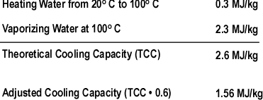
The theoretical cooling capacity (TCC) of water is 2.6 MJ/kg. This value is based on heating a kilogram of water from 20o C to 100o C (0.3 MJ/kg) and vaporizing it completely into steam (2.3 MJ/kg).

Dividing the energy that must be transferred from the upper layer by the TCC calculates the amount of water that would theoretically be required to cool the upper layer from 500o C to 100o C if the energy transfer and conversion of water to steam was 100% efficient. If this was the case, the upper layer could be cooled to 100o C by applying 4.35 kg of water. Given the density of water at 20o C of approximately 1.0 kg/l, this would be a volume of approximately 4.35 liters. However, this assumes instantaneous heat transfer and 100% efficiency in conversion of water to the gas phase. Neither of which is possible in the real world!

Experimental data (Hadjisophocleous & Richardson, 2005; Särdqvist, S., 1996) has shown that the cooling efficiency of water in both laboratory experiments and actual firefighting operations ranges from 0.2 to 0.6. Särdqvist (1996) suggests that an efficiency factor of 0.2 be used for interior fog nozzles. Barnett (as cited in Grimwood, 2005) suggests that an efficiency factor of 0.5 be used for solid or straight stream application and 0.75 for fog application. In actuality, the efficiency of water application varies considerably with the design of the nozzle, skill of the nozzle operator, and a range of other factors. For our examination of gas cooling, we will use an efficiency factor of 0.6 (60%).

Multiplying the TCC of water by 0.6 adjusts the cooling capacity to account for the fact that some of the water applied into the hot gas layer will not turn to steam while passing through the hot gas layer. Some of the droplets will pass through the gas layer and vaporize on contact with hot surfaces (more on this later) and others will fall to the floor, with increased temperature, but remaining in liquid form.

Figure 2. Adjusted Cooling Capacity of Water

Dividing the 11.3 MJ of energy that must be transferred from the upper layer of the compartment by an Adjusted Cooling Capacity (ACC) of 1.56 MJ/kg determines that 7.2 kg (7.2 liters) of water are required to lower its temperature from 500o C to 100o C.

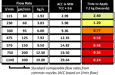
Figure 3 illustrates common flow rates from combination nozzles, Adjusted Cooling Capacity (ACC) and time required to apply the 7.2 kg of water necessary to cool the upper layer of the compartment from 500o C to 100o C.

Figure 3. Flow Rate, Adjusted Cooling Capacity, and Application Duration

As illustrated in Figure 3, if water is applied at 115 l/min (30 gal/min), several short pulses will provide sufficient water application. If the flow rate is increased to 230 l/min, a single pulse is likely to be sufficient. However, if the flow rate is increased further, it is likely that excessive water will be applied. In addition, droplet size increases with flow rate, reducing efficiency.
All Models are Wrong!

This examination of gas cooling provided a simple example of how much water is required to cool the upper layer in a given compartment. While this explanation provides a good way to understand how gas cooling works, it is incomplete. Box and Draper (1987, p. 424)observe that “all models are wrong, but some are useful”. The following factors add quite a bit of complexity to examination of gas cooling:
  • The energy that must be transferred from the upper layer is dependent on the mass of the hot gases and their temperature.
  • Not all of the water applied vaporizes in the upper layer (some droplets travel through the hot gases and vaporize on contact with hot surfaces and others drop to the floor without completely vaporizing).
  • Temperature of the hot gases in the upper layer is not uniform (as assumed in two layer models).
  • Ongoing combustion and energy transfer from hot compartment linings add energy to the hot gas layer.
  • Convection and gravity current influence the movement of hot and cool gases, making conditions dynamic rather than static.

While our model of gas cooling is wrong, I believe that it is useful. Firefighters do not calculate the volume of water required to cool the hot gas layer on the fireground. However, it is important to understand how flow rate and duration impact on effectiveness and efficiency.

Important!

Remember that this example involved gas cooling in a single compartment with static conditions. The flow rate and/or duration of application for fires in larger compartments or direct attack on burning fuel may be quite different.

What’s Next?

One question remains in our examination of gas cooling. Why doesn’t the volume of the upper layer increase when water applied for gas cooling turns to steam? This will be the focus of the third post in this series.

Ed Hartin, MS, EFO, MIFireE, CFO

References

Box, G. & Draper, R (1987). Empirical Model-Building and Response Surfaces. New York: Wiley.

Hadjisophocleous, G.V. & Richardson, J.K. (2005). Water flow demands for firefighting. Fire Technology 41, p. 173-191.

Särdqvist, S. (1996) An Engineering Approach To Fire-Fighting Tactics Sweden, Lund University, Department of Fire Safety Engineering

Svennson, S. (2002). The operational problem of fire control (Report LUTVDG/TVBB-1025-SE). Sweden, Lund University, Department of Fire Safety Engineering.

Grimwood, P. (2005). Firefighting Flow Rate: Barnett (NZ) – Grimwood (UK) Formulae. Retrieved January 26, 2008 from http://www.fire-flows.com/FLOW-RATE%20202004.pdf

Gas Cooling

Saturday, August 14th, 2010

In a compartment fire, the upper layer presents a number of hazards to firefighters including the fact that 1) Smoke is fuel, and 2) the upper layer can be extremely hot. Application of an appropriate amount of water fog into the upper layer reduces the potential for ignition and lowers the temperature of the gases (reducing thermal load on the firefighters working below). While this sounds simple, and fairly intuitive, this basic technique to control upper layer hazards is frequently misunderstood. This is the first in a series of posts that will attempt to provide a simple explanation of the science behind gas cooling as a fire control technique.

How Does it Work

When a pulse (brief application) of water fog is applied into a layer of hot smoke and gases with a temperature of 500o C (932o F) what happens? As the small droplets of water pass through the hot gas layer, energy is transferred from the hot smoke and gases to the water. If done skillfully, the upper layer will not only be cooler and lest likely to ignite, but it will contract (or at least stay the same volume) providing a safer working environment below.

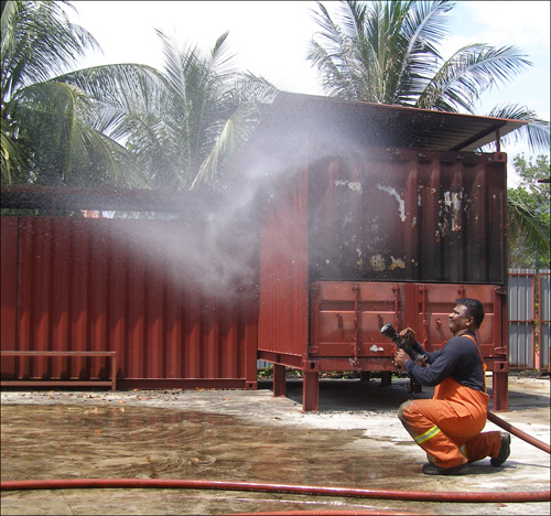
As demonstrated by Superintendent Rama Krisana Subramaniam, Bomba dan Penelamat (Fire & Rescue Malaysia) a short pulse can place a large number of small water droplets in the upper layer that develops during a compartment fire (see Figure 1).

Figure 1. Short Pulse

When presenting this concept, firefighters often present me with two questions:

  • Since water expands approximately 1700 times when turned to steam at 100o C, why doesn’t the upper layer drop down on top of the firefighters?
  • How can such a small amount of water have such a dramatic effect on the fire environment?

Math or No Math?

Using a bit of math, there is a really good explanation as to how gas cooling really works. The best answer is a bit complex, but a good conceptual explanation can be accomplished with a minimal amount of math.

Heating the water to 100o C (212o F) and production of steam transfers a tremendous amount of energy from the hot smoke and gases to the water, reducing the temperature of the hot gases. As the temperature of the hot gases is reduced so is their volume. However, don’t forget about the steam.

When water is turned to steam, it expands. At its boiling point, water vaporized into steam will expand 1700 times. A single liter of water will produce 1700 liters (1.7 m3) of steam. The expansion ratio when water is vaporized is significant. However, due to the tremendous amount of energy required to vaporize the water (and resulting reduction in gas temperature), the final volume of the mixture of hot gases and steam is less than the original volume of hot gases within the compartment.

The Key

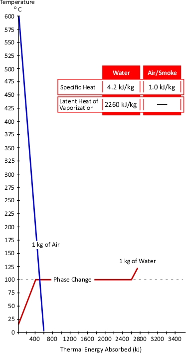
The temperature of the gases is lowered much more than the temperature of the water is increased. Why might this be the case? The key to this question lies in the concepts of specific heat and latent heat of vaporization. As illustrated in Figure 2, the specific heat of smoke is approximately 1.0 kJ/kg (Särdqvist, 2002; Yuen & Cheung, 1999) while the specific heat of water is 4.2 kJ/kg and even more importantly the latent heat of vaporization of water is 2260 kJ/kg. What this means is that it requires over four times the energy to raise the temperature of a kilogram of water by 1o C than it does to lower the temperature of smoke by the same amount. In addition, it requires 2260 times the energy to turn 1 kg of water to steam at 100o C than it does to lower the temperature of 1 kg of smoke by 1o C.

Figure 2. Heating and Cooling Curves of Smoke & Water

While water expand as it turns to steam, the hot gas layer will contract as it’s temperature drops. At the same pressure, change in the volume of a gas is directly proportional to the change in absolute temperature. If the initial temperature of the hot gas layer is 500o C (773 Kelvin) and its temperature is lowered to 100o C (373 Kelvin) the absolute temperature is reduced by slightly more than half (773 K-373 K=400 K). Correspondingly the volume of the hot gases will also be reduced by half.

An Example

Once the underlying concept of gas cooling has been explained, the question of how a small amount of water can have such a dramatic effect may still remain. After all, the preceding explanation compared a kilogram of water to a kilogram of air. Firefighters normally do not usually think of either of these substances in terms of mass. Water is measured in liters or gallons. If measurement of smoke and air is thought of, it would likely be in cubic meters (m3) or cubic feet (ft3). Sticking with SI units, consider the properties of water and smoke as illustrated in Figure 3:

Figure 3. Properties of Water and Smoke

While over simplified, the compartment fire environment can be considered as being comprised of two zones; a hot upper layer and a cooler lower layer, each with reasonably uniform conditions (this is the approach used by computer models such as the Consolidated Model of Fire and Smoke Transport, CFAST).

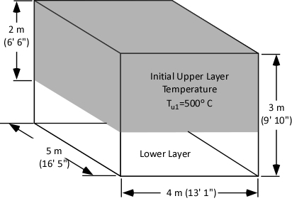
As illustrated in figure 4, our examination of gas cooling will consider a single compartment 4 meters (13’ 1”) wide and 5 meters (16’ 5”) long with a ceiling height of 3 meters (9’ 10”). The upper layer comprised of hot smoke and air is two meters deep and has an average temperature of 500o C (932o F).

Figure 4. Compartment with Two Thermal Zones

What volume of water must be applied into the upper layer to reduce its temperature from 500o C to 100o C?

Just as input of energy is required to increase temperature, energy must be transferred from a substance in order to lower its temperature. The first step in determining the water required for cooling is to calculate the energy that must be transferred from the upper layer to achieve the desired temperature reduction.

The specific heat of smoke is approximately 1.0 kJ/kg. This means that 1.0 kJ of energy must be transferred from a kilogram of smoke in order to reduce its temperature by 1o C. This requires that we determine the mass of the upper layer.

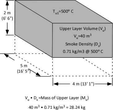
Calculation of mass involves multiplying the volume of the upper layer (40 m3) by the (physical) density of smoke (0.71 kg/m3) at the average temperature of the upper layer (500o C) as illustrated in Figure 5.

Figure 5. Mass of the Upper Layer

Specific heat is the energy required to raise the temperature of a given unit mass of a substance 1o. The same energy must be also be transferred to lower the temperature of a unit mass of a substance by 1o. As illustrated in Figure 3, the specific heat of smoke is 1.0 kJ/kg. Therefore, to lower the temperature of a single kilogram of smoke by 1o C, 1.0 kJ must be transferred from that kilogram of smoke. With an upper layer mass (Mu) of 28.24 kg, 28.24 kJ must be transferred from the upper layer to water applied for gas cooling in order to reduce its temperature by 1o C.

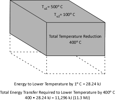
Reduction of upper layer temperature from 500o C to 100o C is a change of 400o. Multiplying 28.24 kJ by 400 determines the total amount of energy that must be transferred to water applied for gas cooling in order to reduce the temperature to 100o C. As illustrated in Figure 6, 11,296 kJ (11.3 MJ) must be transferred from the upper layer to the water to effect a 400o C reduction in temperature.

Figure 6. Energy Transfer Required

Now that we have determined the energy that must be transferred from the upper layer in order to lower the temperature from 500o C to 100o C, it is possible to identify how much water must be applied to accomplish this task. However, that will be the topic of my next post. In addition, I will provide an explanation as to why the volume of the upper layer does not (necessarily) increase when water applied to cool the gases turns to steam.

Ed Hartin, MS, EFO, MIFireE, CFO

References

Särdqvist, S. (2002). Water and other extinguishing agents. Karlstad, Sweden: Räddnings Verket.

Yuen, K. & Cheung, T. (1999). Calculation of smoke filling time in a fire room – a simplified approach. Journal of Building Surveying, 1(1), p. 33-37

Reading the Fire 14

Sunday, August 1st, 2010

Developing and maintaining proficiency in reading the Fire using the B-SAHF (Building, Smoke, Air Track, Heat, and Flame) organizing scheme for fire behavior indicators, requires practice. This post provides an opportunity to exercise your skills using a video segment shot during a commercial fire.

Commercial Fire

This post examines fire development during a fire in an agricultural facility in Spain. First arriving firefighters observed a small amount of light gray smoke issuing from roof ventilators and doorways with low velocity.

Download and the B-SAHF Worksheet.

Watch the first 50 seconds (0:50) of the video. First, describe what you observe in terms of the Building, Smoke, Air Track, Heat, and Flame Indicators; then answer the following five standard questions?

  1. What additional information would you like to have? How could you obtain it?
  2. What stage(s) of development is the fire likely to be in (incipient, growth, fully developed, or decay)?
  3. What burning regime is the fire in (fuel controlled or ventilation controlled)?
  4. What conditions would you expect to find inside this building?
  5. How would you expect the fire to develop over the next two to three minutes

Now watch the next 20 seconds (1:10) of the video clip and answer the following questions:

  1. Did fire conditions progress as you anticipated?
  2. What changes in the B-SAHF indicators did you observe?
  3. How do you think that the stage(s) of fire development and burning regime will change over the next few minutes?
  4. What conditions would you expect to find inside this building now?
  5. How would you expect the fire to develop over the next two to three minutes

    Watch the remainder of the video. If you were the Incident Commander and had crews working inside the building, what information would you communicate to them as conditions change?

    Reading the Fire

    See the following posts for more information on reading the fire:

    Ed Hartin, MS, EFO, MIFIreE, CFO

    Everyday Concepts-Part 4
    Radiation

    Monday, April 12th, 2010

    Firefighters are often provided with an oversimplified explanation of fundamental scientific concepts related to fire behavior. This is done with the intent to make training manuals and texts understandable and to focus on the information that firefighters must know. However, a tremendous opportunity to develop the ability to make sense of fire dynamics and the impact of tactical operations is lost in the process. This series of posts continues to explore ways of building a scaffold to allow firefighters to develop a deeper understanding of firefighting as science.

    Electromagnetic Radiation

    The term radiation is used to describe many different things ranging from visible light, infrared light, and ionizing radiation such as x or gamma rays. Each of these is an example of radiation as an electromagnetic wave produced by the motion of electrically charged particles. Electromagnetic radiation can travel through empty space and air. Radiation can also penetrate through other materials depending on the characteristics of the material and the radiations energy. Some ionizing radiation is in the form of particles (rather than waves), but that is outside the scope of our examination of radiation as a mechanism of heat transfer.

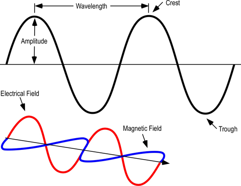
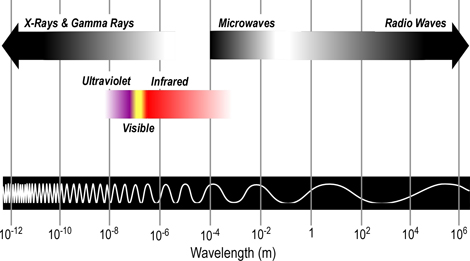
    As illustrated in Figure 1, electromagnetic waves can be described in terms of their wavelength, amplitude, frequency, and energy.

    Most of the electromagnetic spectrum cannot be detected by the human eye. While the electromagnetic spectrum includes radiation in a broad range of wavelengths, those of most interest in the study of fire behavior are categorized as infrared

    Figure 1. Electromagnetic Wave

    wavelength_lr

    From longest to shortest wavelengths, the spectrum is usually divided into the following sections: radio, microwave, infrared, visible, ultraviolet, x-ray, and gamma-ray radiation. Humans can only see a narrow band of visible light, which is a small fraction of the electromagnetic spectrum. We perceive this radiation as the colors of the rainbow ranging from red to violet, with reds having longer wavelengths and violet having shorter wavelengths

    Thermal radiation is electromagnetic radiation emitted from the surface of an object which is due to the object’s temperature. Any material that is above absolute zero gives off some radiant energy. Thermal radiation is generated when heat from the movement of charged particles within atoms is converted to electromagnetic radiation.

    Figure 2. Electromagnetic Spectrum

    electromagnetic_spectrum_lr

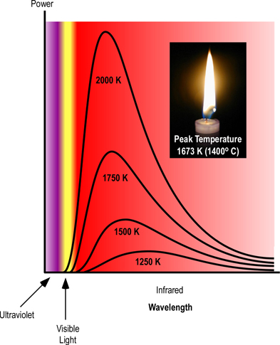
    Figure 3. Planck’s Curve

    planck_curves_lr

    Thermal radiation occurs at a wide range of frequencies. However, as illustrated in Figure 2, the power emitted at each wavelength is dependent on temperature, with the main frequency and power of emitted radiation increasing as temperature increases. This can be observed when color changes from red, to yellow, and then white as an object is heated. While color change is visible, most of the radiant energy is still in the infrared spectrum.

    Electromagnetic waves of any frequency will heat surfaces that absorb them. However, temperatures of hot surfaces, gases, and flames in the fire environment result in emission of electromagnetic waves predominantly in the infrared and visible portion of the spectrum.

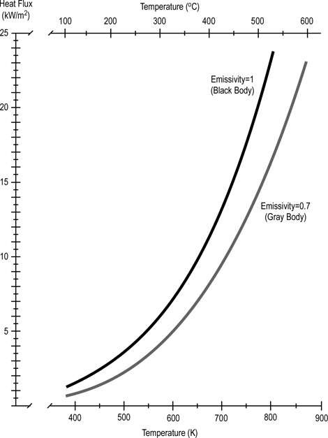
    Stefan-Boltzmann Law: The amount of energy per square meter per second that is emitted by a black body is related to the fourth power of its Kelvin temperature. As temperature increases, emission of radiant energy increases exponentially.

    A black body is a theoretical object that completely absorbs all incoming radiant energy and is also a perfect emitter of radiant energy. Materials encountered in the fire environment do not completely have the characteristics of a black body and may be classified as gray bodies. A gray body absorbs or emits a portion of the radiative flux depending on the emissivity (?).

    Emissivity is the relative ability of the surface of a material to emit radiant energy. It is the ratio of energy radiated by a particular material to energy radiated by a black body at the same temperature. Emmisivity of a black body would be 1.0 with the emissivity of actual materials ranging from approximately 0.1 for highly reflective materials (e.g., polished silver) to 0.97 for fairly efficient absorbers and emitters of radiant energy (e.g., carbon particulate).

    Emission of radiant energy is measured as heat flux (energy transfer per unit of time over a given surface area). The SI unit of measure is joules/second/square meter or (since a watt is a J/s) watts/square meter (w/m2).

    Figure 4. Stefan Boltzmann Law

    Stefan-Boltzmann_v2_lr

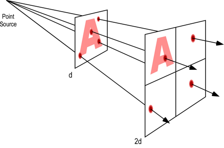
    Electromagnetic radiation spreads out as it moves away from its source. As a result, the intensity of the radiation decreases as distance from the source becomes greater (as illustrated in Figure 5). The simplest example involves a point source of radiation (distance from the source is much greater than the size (e.g. surface area) of the emitter). With a point source, reduction in radiation intensity follows the inverse square law.

    Figure 5. Radiation Intensity Decreases With Distance

    inverse_sqare_law_lr

    Inverse Square Law: For point sources, intensity of the radiation varies inversely with the square of the distance from the source. Doubling the distance reduces intensity of the radiation by a factor of four (1/4 of its original value).

    When radiation is emitted from other than a point source (as it is under fire conditions), variation of the radiation intensity with distance is more complex. If the area of the source is large compared with the distances involved, intensity decreases with distance but does not follow a simple law. As a rough guide, if the distance from the source is greater than about 5 times the dimensions of the source, the inverse square law can be applied.

    More to Follow

    Subsequent posts in this series will examine physical and chemical changes and the process of combustion.

    Ed Hartin, MS, EFO, MIFireE, CFO

    Everyday Concepts-Part 3
    Convection

    Sunday, April 4th, 2010

    Things to Think About

    Methods of heat transfer are often presented to firefighters in a simplistic way with the expectation that they will understand the basic concepts and are assessed on their ability to recall the definitions of conduction, convection, and radiation. Unfortunately this does not provide a solid basis for understanding phenomena encountered on the fireground.

    Convection

    In general terms, convection refers to movement of molecules within fluids (i.e., liquids and gases). Convection results in both heat and mass transfer (these are interrelated as extensive properties such as thermal energy are dependent on mass). Convection involves diffusion due to random movement of individual molecules (Brownian motion) and large scale motion of currents in the fluid (advection).

    Natural Convection

    Natural or free convection results from temperature differences within a fluid. As a fluid is heated, it expands while mass remains the same. Decreased density (mass/unit volume) makes the heated fluid more buoyant, causing it to rise. As the heated fluid rises, cooler fluid flows in to replace it. Natural convection is one of the major mechanisms of heat transfer in a compartment fire, heated air and smoke rise and cooler air moves in to replace it. This process transfers thermal energy, heating other materials in the compartment and also transfers mass as smoke moves out of the compartment and cool air (containing oxygen necessary for continued combustion) moves into the compartment.

    In the late 1700s, French scientist Jacques Charles studied the effect of temperature on a sample of gas at a constant pressure. Charles, found that as the gas was heated, the volume increased. As the gas was cooled, the volume decreased. This finding gave rise to Charles Law.

    Charles’ Law: At a constant pressure, the volume occupied by a fixed mass of gas is directly proportional to its thermodynamic temperature (V?T).

    Figure 1. Charles Law

    charles_law

    Density is mass per unit volume (?=m/V). As the volume of a given mass of gas increases, it becomes less dense (and more buoyant). If unconfined, gases that are less dense than the surrounding air will rise (resulting in natural convection currents). In a compartment fire, conditions are not as simple as stated in Charles Law. Initially, hot gases resulting from a fire in a compartment are relatively unconfined as the volume of smoke and hot gases is small in relation to the size of the compartment and there may be some leakage of smoke from the enclosure. However, as the fire continues to develop, the volume of smoke increases and conditions change.

    Gay-Lussacs Law: At a constant volume and mass, the pressure exerted by a gas is directly proportional to its thermodynamic temperature (P?T).

    The pascal (Pa) is the standard international unit of measure for pressure (force per unit area) and is defined as one newton per square meter (N/m2). To provide a point of reference for firefighters more familiar with pounds per square inch (psi) as a unit of measure for pressure, 1 Pa = 0.000145 psi. Low pressures (such as the pressure generated by temperature increases in a compartment fire) are measured in Pa while higher pressures (such as fire pump discharge pressure) are more commonly measured in kilopascals (kPa=1000 Pa).

    As illustrated in Figure 2, if the volume is constant (e.g., the gas is confined) doubling the temperature in Kelvins, doubles the pressure in pascals (Pa).

    Figure 2. Gay-Lussac’s Law

    gay-lussacs_law

    When a fire is unconfined (e.g., outdoors), convection is influenced primarily by differences in density between hot fire gases and cooler air. Convection as a result of a fire in an enclosure (e.g., compartment fire) is significantly influenced by differences in density and differences in pressure.

    Figure 3. Natural Convection

    convection_unconfined_confined

    Forced Convection

    In forced convection, energy is carried passively by fluid motion which occurs independent of the heating process.

    While at first glance, it may appear that this type of convection would not be encountered in the fire environment, but it is extremely important. Forced convection can be caused by natural effects such as wind blowing into an opening (e.g., window broken due to fire effects). This type of forced convection can quickly create untenable conditions both inside the compartment and in adjacent spaces (e.g., rooms, hallways). Forced convection can also have a positive influence on the fire environment. One example would be the use of positive pressure ventilation, in which a blower (fan) is used to create an air flow from an inlet to an exhaust opening, removing hot smoke and gases from the compartment.

    Figure 4. Forced Convection/Wind Driven Fire

    wind_driven

    Note: Adapted from Fire Fighting Tactics Under Wind Driven Fire Conditions: 7-Story Building Experiments.

    Factors Influencing Convective Heat Transfer

    Heat transfer by convection is more complex than conduction as there is no single property such as thermal conductivity that can be used to describe the mechanism of heat transfer. Factors that influence heat transfer by convection in the fire environment include temperature difference between the fluid (gas) and surfaces, fluid velocity, and turbulence (related to surface roughness and compartment configuration).

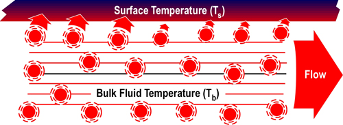
    Figure 5 illustrates convective heat transfer with laminar (smooth) fluid flow. Energy is transferred from higher temperature fluid molecules to the cooler surface. Bulk fluid temperature (Tb) is the temperature of the fluid some distance away from the surface. As heat is transferred, the temperature of the fluid molecules is lowered (with a corresponding rise in surface temperature). These cooler molecules insulate the surface from the higher temperature molecules further away from the surface, slowing convective heat transfer.

    Figure 5. Convection-Laminar Flow

    convection_laminar_flow

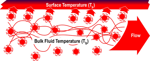
    When velocity and/or turbulence increases, cooler molecules that have transferred energy to the surface are quickly replaced by higher temperature molecules, resulting in increased convective heat transfer as illustrated in Figure 6. This is the same phenomena as wind chill, except in this case, energy is transferred from a hot fluid (gas) to a solid surface rather than from a hot surface (i.e., your skin) to a cooler fluid (air).

    Figure 6. Convection-Turbulent Flow

    convection_turbulent_flow

    More to Follow

    Subsequent posts in this series will examine radiant heat transfer and then move on into discussion of the process of combustion.

    Ed Hartin, MS, EFO, MIFireE, CFO

    References

    Kerber, S. & Madrzykowski, D. (2009) Fire Fighting Tactics Under Wind Driven Fire Conditions: 7-Story Building Experiments, NIST Technical Note 1629. Gaithersburg, MD: National Institute of Standards and Technology.

    Everyday Concepts:
    Energy, Heat, & Temperature-Part 2

    Sunday, March 21st, 2010

    I am using this series of posts to work through the process of developing a chapter on the foundational scientific concepts related to practical fire dynamics and fire control theory. My hope is to take the middle ground between the oversimplified and unsupported explanations provided in most texts intended for firefighter training and the higher level materials intended for fire protection engineers. This is proving to be no small task! Your feedback on my success (or lack thereof) in providing scientifically sound, but reasonably simple explanations would be greatly appreciated.

    Back to Everyday Concepts Part 1

    When faced with the challenge of developing firefighters understanding of energy, temperature, heat, and power in a limited timeframe, I generally avoid detailed discussion of the actual definition of the SI unit for energy, the Joule, and the mechanical equivalent of thermal energy. I have found that illustrating the concept of the Joule as it relates to thermal energy in terms of heating water to serve the purpose. However, as I looked back at the first post in this series, I think it would be useful to go back to the source, and examine James Joules experiments that made the connection to the equivalence of mechanical and thermal energy.

    While not commonly used in scientific work, the American fire service has typically used the British thermal unit (Btu) as a measure of thermal energy. The Btu is defined in terms of the heating effect of energy transferred to water. One Btu is the energy required to raise the temperature of one pound of water by one degree Fahrenheit.

    As discussed in the first post in this series, the SI unit of measure for energy is the Joule (J) which is defined in mechanical terms, but is applicable to all forms of energy.

    In the mid 1800s English physicist James Joule demonstrated the equivalence of mechanical and thermal energy by using a mechanical apparatus to stir water in an insulated container with paddles driven by a falling weight (see Figure 1).

    Joule (1845) reported that based on analysis of data from a number of experiments, that expenditure of mechanical energy of 817 ft/lbs (the energy required to raise 817 pounds to a height of one foot) was the equivalent of an increase in temperature of one pound of water by one degree Fahrenheit. Conversion to SI units of measure is a bit complex, but 817 ft/lbs is equal to 1107 Newton/meters (the energy required to raise a mass of 1107 N to a height of 1 meter). While a non-standard measure of energy, the Newton/meter (N/m) provides a direct comparison to ft/lbs. In mechanical terms, a N/m equals the SI unit for energy, the Joule. Expressed in SI units, 1107 Joule of energy were required to raise the temperature of 0.454 kg (1.0 lbs) of water 0.56o C (1o F). This is quite close to the currently accepted conversion value in which 1055 J = 1 Btu.

    Figure 1. Demonstration of the Mechanical Equivalent of Heat

    joule_apparatus_lr

    Note: Joule used a lesser weight falling over a greater distance, repeated a number of times. This drawing is simplified to provide a conceptual illustration.

    Heat Transfer

    In everyday language the word heat is used in a variety of ways (many of which are incorrect from a thermodynamic perspective). In thermodynamics, heat is a method of energy transfer. Heat is not a form of energy (a commonly stated misconception), but simply the name of the process of energy transfer based on temperature difference. Objects do not have heat, they have thermal energy, and heat is thermal energy in the process of transfer to objects having a lower temperature.

    Even though it involves energy transfer, heat is not the same as work. Remember that work involves force causing movement in a direction influenced by that force (and if no movement in that direction occurred, no work is done). Energy transferred by heat results in an increase in molecular movement, but not in a specific direction, therefore no work is done. However, this does not mean that energy transferred by heat cannot be transformed into mechanical energy and accomplish work.

    Transfer of energy from one object to another must be classified as heat or work. When energy content changes, it must be the result of heat, work, or a combination of both. Heat and work are processes by which energy is exchanged rather than energy itself.

    The word flow is often used in discussing heat transfer (e.g., energy flows from objects with higher temperature to those with lower temperature). This helps visualize patterns of movement, but it is important to remember that neither energy nor heat is a fluid. Heat is the process of energy transfer due to temperature differences. This energy transfer takes place in a variety of different ways.

    Second Law of Thermodynamics: There are several ways to state this law. The simplest is that heat cannot spontaneously flow from a material at lower temperature to a material at higher temperature. However, thermal energy moves from materials at high temperature to those having lower temperatures until they have the same temperature (equilibrium).

    There are three methods of heat transfer, conduction, convection, and radiation. Each of these has significant impact on the processes of combustion, fire development, and fire control.

    Conduction

    Conduction of heat occurs when adjacent atoms vibrate against one another or as electrons move from atom to atom. Heat transfers through solid materials and between solid materials in direct contact with one another by conduction. The atoms in liquids and gases are further apart, reducing the probability of collision and transfer of thermal energy.

    Figure 2. Conduction

    conduction

    Factors Influencing Conductive Heat Transfer

    The factors influencing conduction are temperature difference, length (or thickness), cross sectional area, and the thermal conductivity of the conductor.

    Thermal conductivity is the measure of the quantity of thermal energy which flows through a conductor. In addition to form, there are a number of factors influencing thermal conductivity of materials including molecular bonding, structure, and density. Units of measure for conductivity must account for the amount of energy transferred in a given amount of time, thickness (or distance), and temperature difference. The SI units of measure for thermal conductivity are Watts per Kelvin per Meter (W?K?m). While appearing to be complex, this measure is fairly straightforward; indicating the number of Watts (Joules/second) transferred a distance of one meter for each Kelvin of temperature difference (Figure 3)

    Figure 3. Thermal Conductivity

    thermal_conductivity_lr

    When the temperature of one surface of a solid material is higher than another, heat will move through the material. Depending on the characteristics of the material, this conductive heat transfer may be slow or it may occur quickly. The rate of heat transfer is defined by the coefficient of thermal conductivity.

    As illustrated in Figure 3, the total amount of heat transfer is dependent on the coefficient of thermal conductivity, difference in temperature, and cross sectional area of the conductor. It is difficult to measure thermal conductivity as it describes a semi-static situation with a constant temperature gradient. However, heat transfer results in temperature changes towards equilibrium (equal temperature at all points in the conductor).

    A high coefficient means heat moves very quickly; a low coefficient means heat moves very slowly. As illustrated in Table 1, the thermal conductivity constant (k) for different materials varies considerably.

    Table 1Thermal Conductivity Table

    thermal_conductivity_table_lr

    Metals are usually the best conductors of thermal energy due to their molecular bonding and structure. Metallic chemical bonds have free-moving electrons and form a crystalline structure which aids in transfer of thermal energy as illustrated in Figure 4.

    Figure 4. Conduction in Metals

    metal_conductivity_lr

    Because the outer electrons in metals are shared by all the atoms, they are not considered to be associated with any one atom. Since these electrons are attracted to many atoms, they have considerable mobility that allows for the good thermal conductivity seen in metals.

    In general, density decreases so does conduction (some unusual materials such as carbon foam, have low density and high conductivity). Therefore, most fluids (and especially gases) are less conductive. This is due to the large distance between atoms in a gas: fewer collisions between atoms means less conduction. Conduction is dependent on the area being heated, temperature differential, and thermal conductivity of the material.

    Whats Next

    The next post in this series will examine convection and radiation as mechanisms of heat transfer. In addition, I will be starting a series of posts to discuss a comprehensive approach for nozzle testing from an operational perspective.

    Ed Hartin, MS, EFO, MIFireE, CFO

    References

    Joule, J. (1845). On the existence of an equivalent relation between heat and the ordinary forms of mechanical power. Philosophical Magazine, 3(xxvii), p. 205.

    Everyday Concepts: Energy, Heat, & Temperature-Part 1

    Saturday, February 27th, 2010

    Everyday Concepts

    Firefighters, like most everyone else, have a commonsense, everyday understanding of energy, heat and temperature. However, this everyday understanding is likely to be considerably different than the way these concepts are defined and used in science. Think about how heat and temperature are used on a day-to-day basis. On a sunny summer day, people are likely to say that it is hot because they feel hot or because the thermometer indicates a temperature is high. This may lead people to believe that temperature is a measure of hotness or heat. On the other hand, scientists view these concepts considerably differently!

    So what! What difference does it make if we use our commonsense, everyday understanding of energy, heat, and temperature in our effort to make sense of fire dynamics? Why is this important?

    If you are going to take a trip, it is useful to understand the concept of distance and have some type of units (e.g., kilometers or miles) to describe how far away your destination is. When describing a building, firefighters indicate the number of stories and dimensions (e.g., meters or feet). Having a good grasp of the concepts of energy, heat and temperature provides a way to describe the fire potential of different types of fuel, the size of a fire in terms of energy and power, and the thermal environment encountered by firefighters.

    Take a minute and think about how you would define energy, heat, and temperature. Write your ideas down on a piece of paper so you can come back to them later. Dont worry about the textbook definition, just write down what you think these words mean. After reading the rest of this post, come back to your notes and see how your understanding of energy, heat, and temperature has changed.

    Energy, Heat, and Temperature in Firefighting

    For many years, firefighters in the United States learned about British thermal units (Btu) as a measure of energy. A British thermal unit is the amount of energy required to raise the temperature of 1 pound of water (at 60o Fahrenheit (F)) 1o F. Firefighters often can state a reasonable approximation of this definition and the Btu seems to be a fairly simple unit of measure with direct applicability in the firefighting context.

    Before an observer can formulate and assent to an observation statement, he or she must be in possession of the appropriate conceptual framework and a knowledge of how to appropriately apply it (Chalmers, 1999, p. 11). It is one thing to recognize a definition, but it is another thing entirely to be able to use this information in a broader context and make sense of things! For example a young child may be able to identify a red apple, but may not have a good understanding of what makes this fruit an apple (as opposed to a pear) or how a red apple and a green apple can both be apples. Developing an understanding of the fundamental scientific concepts that underlie fire dynamics and firefighting is much the same. Knowledge and understanding must extend beyond simple recognition of, or the ability to restate definitions and concepts presented in a text of lecture.

    Thermodynamics

    Thermodynamics is a branch of physics that describes processes that involve changes in temperature, transformation of energy, and the relationships between heat and work. Fire and firefighting also involves changes in temperature, transformation of energy, heat and work. Thermodynamics, like much of the rest of science, takes terms with an everyday meaning and sharpens them some would say, hijacks them so that they take on an exact unambiguous meaning (Atkins, 2007, p. 3).

    Thermodynamics deals with systems. A thermodynamic system is one that interacts and exchanges energy with the area around it. A system could be as simple as a block of metal or as complex as a compartment fire. Outside the system are its surroundings. The system and its surroundings comprise the universe.

    While in general terms the universe includes everything, we will generally look at things on a smaller scale. For example we might consider a burning fuel package as the system and the compartment as the surroundings. On a larger scale we might consider the building containing the fire as the system and the exterior environment as the surroundings.

    Figure 1. Thermodynamic Systems

    thermodynamic_system

    Thermodynamic systems can be classified on the basis of their interaction with the surroundings.

    • Isolated systems do not exchange energy or matter with their environment.
    • Closed systems exchange energy but not matter with their environment.
    • Open systems exchange energy and matter with their environment. A boundary allowing matter exchange is called permeable.

    Laws of Thermodynamics: These laws summarize the properties of energy and its transformation from one form to another. Numbered from zero to three, these laws are both simple and extremely complex. This series of posts examines the laws of thermodynamics in the context of fires and firefighting to move from theoretical to practical application.

    Energy

    Energy is a fundamental concept in physical science, but is difficult to define in a way that is meaningful on an everyday basis. Energy is the ability to do mechanical work or transfer thermal energy from one object to another. Energy can only be measured on the basis of its effects. There are basically two kinds of energy, kinetic and potential. Kinetic energy is associated with motion of an object and potential energy is that which is stored and may be released at a later time.

    There are a number of different forms of energy; mechanical, chemical, electrical, radiant, and thermal. However, each has the ability to be transformed into work, which is force applied to an object, causing it to be displaced. In thinking about energy and work it is important to keep two things in mind:

    • Energy is the capacity to do work.
    • Work involves force causing movement in the direction of that force.

    If the force does not influence movement in the direction of the force, no work was done.

    Newtons (named after Isaac Newton) are the standard international (SI) unit for force. A Newton is the amount of force required to give a mass of one kilogram an acceleration of one meter per second squared. However, it may be easier to visualize force in terms of weight. In our everyday environment, weight is the force exerted as a result of our mass and the effects of gravity. For example, a kilogram (which is a unit of mass) exerts a downward force of 10 Newtons (or 2.2 pounds). To make things more complicated, kilograms are used in everyday language to express weight (rather than Newtons). This is because on earth, weight and mass are directly proportional.

    The SI unit for energy (capacity to do work) is the Joule. A Joule is a force of one Newton causing displacement of an object a distance of one meter. For example, approximately one Joule of energy is required to lift a small apple (which weighs one Newton (or 0.22 pounds) a distance of 1 meter. In that energy is the capacity to do work, the Joule is also used to measure energy (regardless of its form).

    While mechanical energy may be of interest to firefighters, what does this have to do with thermal energy and fire behavior? One really big puzzle is how Joules which are defined in terms of mechanical energy can be used to measure thermal energy? This is a really good question, but several more scientific concepts are needed in order to make sense of the answer.

    Substances have potential chemical energy based on the bonds within and between their atoms and molecules. Formation, breaking, or rearrangement of these chemical bonds results in transfer of energy into or out of the substance. For example, in combustion the reaction of an oxidizer and fuel results in transformation of chemical potential energy into thermal and radiant kinetic energy. Thermal energy is molecular kinetic energy resulting from molecules moving around in random directions as well as molecular rotation and vibration. Radiant energy is comprised of electromagnetic waves in the infrared region of the electromagnetic spectrum although some is in the visible region. The term thermal radiation distinguishes this form of electromagnetic radiation from other forms such as radio waves and ionizing radiation

    First Law of Thermodynamics: Energy cannot be created nor destroyed only transformed from one form to another. For example, in combustion the chemical reaction between oxygen and fuel results in transformation of chemical energy to thermal and radiant energy. However, the total amount of energy remains the same.

    Temperature

    Temperature is a measure of the average kinetic energy. Temperature of any substance, whether solid, liquid, or gas, is directly related to all motion (kinetic energy) of its molecules. This is especially important for liquids and solids because the kinetic energy of these substances is almost entirely vibrational and rotational. All molecules above a temperature of absolute zero (the temperature at which molecular motion stops) are in a continual state of motion and possess kinetic energy.

    The Kelvin is the standard international unit for temperature. In this scale, temperature is measured in Kelvins (K), not degrees (as with the Celsius and Fahrenheit scales). While the least common in everyday use, the Kelvin thermodynamic temperature scale is important in understanding thermal energy, temperature, and heat. With the Kelvin scale, 0 K is absolute zero, the theoretical absence of all thermal energy.

    While the Kelvin is the standard international unit for temperature, the Celsius scale is commonly used as both an everyday (outside the United States) and scientific measure of temperature. The degree Celsius (o C) is the same increment of measure as the Kelvin, the difference between these two scales is the zero point on the scale. With the Celsius scale 0o C is the freezing point of water (273.15 K) while as previously noted 0 K (-273.16o C) is absolute zero.

    In the United States, the Fahrenheit scale is commonly used to measure temperature on an everyday basis. Unlike the Celsius scale where the difference between the freezing and boiling points of water is 100o, the Fahrenheit scale places the freezing point at 32o and boiling point at 212o, a difference of 180o.

    Figure 2. Common Temperature Scales

    temperature_scales

    Note: Equivalent temperatures have been rounded to the closest whole unit (i.e., degree, kelvin).

    The Kelvin temperature scale is used in scientific work involving thermodynamics, because this scale starts at absolute zero (the point at which a substance has no thermal energy). This means that temperature in Kelvins is a measure of the absolute temperature. Use of an absolute temperature scale allows expression of physical laws and mathematical formulas more simply.

    For example, 100o C is not twice as high a temperature as 50o C (even though at first glance it appears that it is). This becomes clear when using the Kelvin scale. A temperature of 50o C is 323.15 K while 100o C is 373.15 K, an increase of just over 13% in absolute temperature.

    Third Law of Thermodynamics: In the complete absence of molecular kinetic energy, the temperature of a substance would be absolute zero. Absolute is 0 K or -273.15 C.

    Measuring Energy

    As previously discussed, the SI unit of measure for energy is the Joule (J). While defined in terms of mechanical work, the joule is used for all forms of energy. In the standard international system of units, prefixes such as kilo (thousand) and mega (million) are used to provide incrementally larger units of measure. In the case of energy, a kilojoule (kJ) would be a thousand joules and a megajoule (MJ) would be one million joules.

    While not commonly used in scientific work, the American fire service has typically used the British thermal unit (Btu) as a measure of thermal energy. The Btu is defined in terms of the heating effect of energy transferred to water. In order to provide a simple explanation of the Joule as a unit of measure for thermal energy and allow a direct comparison to the Btu, Figure 3 describes the J in terms of energy transfer to water and provides a comparison to the Btu.

    Figure 3. Joule and British Thermal Unit

    joule_btu

    * In this case, Ounces is a measure of volume not mass (or weight). Another confusing aspect of the traditional system of measure used in the United States!

    As illustrated in Figure 3, addition of 4186 joule of energy to a kilogram of water raises its temperature (average internal kinetic energy) by one degree Celsius. Similarly, adding one British thermal unit of energy to a pound of water raises its temperature by one degree Fahrenheit. Directly comparing these two examples is a bit complex as the units of measure for both energy (J & Btu) and temperature (o C & o F) are different.

    Some properties of materials are independent of their mass, color would be one example. Other properties are dependent on mass. Weight, would be the most obvious, but other properties are also dependent on the mass of material present.

    Figure 4. Energy and Temperature Simulation

    TempEnergySimulation

    Note: This illustration was adapted from a simulation in Energy: Thermal Energy, Heat and Temperature, a National Science Teachers Association knowledge object.

    The example provided in Figure 4 examines the difference between temperature and thermal energy as related to mass. The container labeled A initially contains a specific mass of liquid with a temperature of 30o C and a total thermal energy of 8 J. Liquid is moved from the container labeled A to the one labeled B. How does the temperature of the liquid and thermal energy in each container change as this transfer takes place? The temperature of the liquid remains the same regardless of the quantity in each of the containers. However, as the mass of liquid in each container changes, the thermal energy of the liquid in the container changes as well. Related to average thermal energy, temperature is independent of mass, while the total thermal energy relates directly to mass. Properties of materials fall into two categories. Extensive properties (like energy) are dependent on the quantity (mass) of material while intensive properties (like temperature) are not.

    Whats Next?

    The next post in this series will examine the concept of heat and the relationship between heat, energy, and temperature.

    Ed Hartin, MS, EFO, MIFireE, CFO

    References

    Atkins, P. (2000). Four laws that drive the universe. Oxford, UK: Oxford University Press

    Chalmers, A. (1999) What is this thing called science? (3rd ed.). Indianapolis, IN: Hackett.

    National Science Teachers Association (NSTA). (2006). Energy: Thermal energy, heat and temperature. Retrieved February 27, 2010 from http://www.nsta.org/store/product_detail.aspx?id=10.2505/7/SCB-EN.3.1