Posts Tagged ‘3D firefighting’

FAQ-Fire Attack Questions Part 3

Saturday, April 27th, 2013

Amazing!

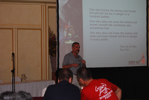
Thursday morning saw a sea change in perspectives on fire behavior in the United States! Over 2500 people were in the big room at FDIC to hear BC George Healey (FDNY), Dan Madryzkowski (NIST), Steve Kerber (UL), and LT John Ceriello (FDNY) talk about fire research conducted on Governors Island in New York.

fdic_governors_island

This excellent presentation emphasized the importance of understanding fire behavior and the influence of flow path and provided several key tactical lessons, including:

  • Importance of control, coordination, and communication between crews performing fire attack and those performing tactical ventilation
  • The effectiveness of anti-ventilation such as closing the door (even partially) on slowing fire development
  • Effectiveness of water quickly applied into the fire compartment (from any location, but in particular from the exterior) in slowing fire progression
  • The demonstrated fact that flow path influences fire spread and not application of water. You can’t push fire with water applied into the fire compartment.
  • Importance of cooling the hot smoke (fuel) in the upper layer

Several years ago, who would have thought that a presentation on fire dynamics and research would have drawn this number of people to a presentation at FDIC. Kudos to FDNY, NIST, and UL for their ongoing work in developing an improved understanding of fire dynamics and firefighter safety.

FAQ (Fire Attack Questions) Continued

I had the opportunity to visit with Captain Mike Sullivan with the Mississauga Ontario Fire Department while at FDIC and we are continuing our dialog with another series of questions related to the characteristics of water fog and its use of a fog pattern for self-protection when faced with rapid fire progression in a structure fire.

The next three questions deal with using a fog stream for protection. In the IFSTA Essentials of Firefighting 5th edition it states that “wide fog patterns can also protect firefighters from radiant heat”, however in the IFSTA Essentials of Firefighting 3rd edition it states “In the past, water curtain broken stream nozzles were commonly used for exposure protection. However, research has indicated that these nozzles are only effective if the water is sprayed directly against the exposure being protected”. This tells me that fog patterns cannot protect from radiant heat.
gas_firefighting

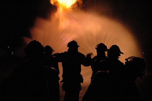
Another question for which the answer is “it depends”. Both statements are correct (in context). Water droplets reduce radiant heat by absorbing energy and scattering the radiant energy. The effectiveness of these mechanisms depends on droplet size, wavelength of the radiation, geometric dimensions of the water spray, and density of the fog pattern. To put this in context, firefighters use a water spray for protection when approaching a flammable gas fire. In this context, the high density of the spray in proximity of the nozzle is quite effective. In contrast, application of a water spray between a fire and exposure is likely to be much less dense, and thus less effective in protecting the exposure than simply applying water to the exposure to keep its temperature <100o C.

In the past there was a belief (which some still believe) that if you find yourself in a bad situation in a house fire you can simply switch to a wide fog and it develops an “umbrella of protection from the heat and fire”. I believe this to be false. What I do think has happened in the past is that firefighters have found themselves in a room with extreme rollover or even had pockets of unburned gas igniting around them. When they used this technique they didn’t protect themselves with an umbrella of fog protection but they cooled the smoke layer and made the situation better.

This also is an interesting question, there are incidents where firefighters have opened the nozzle when caught in rapid fire progression and have survived (not necessarily uninjured), likely due to the cooling effects of the water spray. However, I would agree that this does not provide “an umbrella of protection” like a force field that provides complete protection. The benefit is likely by cooling of the hot gases above and potentially controlling some of the flaming combustion in the immediate area. However, as continuous application will likely not only cool the hot upper layer, but also generate a tremendous amount of steam on contact with compartment linings, the environment will not be tenable in the long term. However, this environment is likely more survivable than post-flashover, fully developed fire conditions.

Much the same as in driving or riding in fire apparatus, the best way to avoid death and injury in a crash is to not crash in the first place. If firefighters recognize worsening fire conditions, they should cool the upper layer to mitigate the hazards presented, if this is ineffective, withdrawing while continuing to cool the upper layer is an essential response.

My last comment on this; and this is where I am not really sure. If you are in a situation where you need to back out quickly, would it work to use a fog stream to push the heat away as you are reversing out of the structure? You would only do this for a short time while you retreat.

If you cannot put water on the fire to achieve control (shielded fire) or the heat release rate (HRR) of the fire exceeds the cooling capacity of your stream you are in a losing position. When faced with rapidly deteriorating thermal conditions, it is essential to cool the upper layer. It is important to note that cooling, not simply “pushing the heat away” is what needs to happen in this situation. This action reduces heat flux from both convective and radiant transfer. Adequate water must be applied to accomplish this task, as temperature increases so too does the water required. Long pulses provide a starting point, but the pulses need to be long enough to deliver the required water. If needed, flow could be continuous or near continuous while the crew withdraws. In much the same manner a crew working with a solid stream nozzle would operate the nozzle in a continuous or near continuous manner and rotate the stream to provide some cooling to the upper layer while withdrawing.

There are those who believe that you can use a fog stream to protect yourself in a house fire by pushing the heat away from you as you advance on the fire. I believe you can push heat away from you and it happens in 2 distinct ways,  the wide fog with the entrained air is literally pushing the heat away from you and you have now created high pressure in an area that was low pressure (typically you are near an open door) so you have effectively changed the flow path. Having said this, I feel the benefits are short lived. With this fog pattern you will also be creating a lot of steam which will continue expanding until it’s temperature reaches equilibrium with the rest of the fire compartment (expansion could be as high as 4000 times). With all this pushing and expansion you are now creating high pressure in an area down stream from you that had previously been a low pressure area. As we know, everything is trying to move from high to low pressure, now the low pressure area is directly behind the nozzle. Now you are in a situation where not only is the heat coming back behind the nozzle but there is an enormous amount of steam being created and heading your way. The confusion here is most likely with the techniques we use when practicing for gas fires, we do this outside where there is an endless amount of space to push the heat away (I read this part in a good article in Fire Engineering).

The impact of continuous application of a fog stream (or any stream for that matter) as you advance is dependent on a number of factors, principal among which are the flow path and where steam is produced (in the hot gas layer versus on contact with surfaces). Continuous application is likely to result in vaporization of a significant amount of water on contact with surfaces; this will result in addition of steam to the hot upper layer without corresponding contraction of the hot gases that results from vaporization of water while it is in the gases. Without ventilation in front of the fog stream (or any stream for that matter), this can result in a reduction in tenability. However, when ventilation in front of the stream is provided, a combination attack (using a fog pattern, straight, or solid stream) can be quite effective for fully developed fire conditions.

I was hoping you could elaborate on the term “painting”. It is defined as a “gentle application of water to cool without excess steam production”. The hard part as a firefighter is the word “gentle” as this word doesn’t register in firefighter lingo. I can see this during overhaul but was hoping you could elaborate.

The way that I typically explain the concept of “gentle” is using a fire in a small trash can or other incipient fire inside of a building. If you use a hoseline to extinguish this fire, it is unlikely that you will need a high flow rate or application of the stream with the bail of the nozzle fully open. It would be appropriate to simply open the nozzle slightly on a straight stream and apply a small amount of water to the burning fuel.

Surface cooling can be done using a vigorous application from a distance when faced with a well involved compartment. In this situation, the reach of the stream is appropriately used to extinguish the fire and cool hot surfaces from a distance to minimize thermal insult to firefighters while quickly achieving control. However when faced with hot and pyrolizing compartment linings or contents, it may be useful or necessary to cool these surfaces from closer proximity. In this case applying water with force will result in much of the water bouncing off the surfaces and ending up on the floor. Painting involves using a straight stream or narrow fog pattern with the nozzle gated back to provide a gentle application resulting in a thin layer of water on the hot surface. As you note, this is most commonly used during overhaul, but could be used anytime that there is a need to cool hot, pyrolizing, but unignited surfaces.

Next week Mike and I will conclude this series of FAQ with a look at pyrolysis and flow path.


FAQ-Fire Attack Questions: Part 2

Saturday, April 20th, 2013

nozzle_technique

Captain Mike Sullivan with the Mississauga Ontario Fire Department and I are continuing our dialog with another series of questions related to the science behind fire attack and fire control methods. Mike’s next several question deal with gas and surface cooling.

I know the best way to extinguish a fire is to put water on it but my questions below deal with a situation of large, open concept homes where you can see the entire main floor except the kitchen cooking area, in many cases this area is not separate from the open floor plan but around the corner so we can’t hit the fire until we get around that corner. My questions are all geared around how to cool the environment as you make your way to the fire (if you need to go to the very back of the house to get to the fire, fire can’t be seen).

When you answered the question about the effects of flowing a straight/solid stream across the ceiling it sounds as if this is really only surface cooling and not effectively gas cooling. If this is true then I was wondering what the value of doing this is, what are the main benefits of cooling the ceiling, walls and floor (and any furniture etc. the water lands on)? Also, what do you recommend to those departments that only use solid bore nozzles?

Use of a solid (or straight) stream off the ceiling has some effect on cooling the gases, but this is limited as the droplets produced are quite large and do not readily vaporize in the hot upper layer (great for direct attack, but not so much for gas cooling). The value of doing this is that any energy taken out of the hot upper layer (buy cooling the gases or by cooling surfaces and subsequent transfer of energy from hot gases to the cooler surfaces) will have some positive effect. In addition, hot combustible surfaces, depending on temperature are likely pyrolizing and adding hot, gas phase fuel to the upper layer. Cooling reduces pyrolysis and the fuel content of the smoke overhead.

The following video of the “Nozzle Forward”, Aaron Fields, Seattle Fire Department demonstrates some excellent hose handling techniques and also provides an illustration of how a solid stream nozzle can be used to cool hot gases by breaking up the stream on contact with compartment linings. Have a look at the video between 2:00 and 2:30 where the nozzle is being rotated as in a combination attack while advancing down a hallway. Note that the stream breaks up on contact with the ceiling and walls, providing a distribution of large droplets in the overhead area.

This technique can be quite effective when faced with a large volume of fire and ventilation is provided in front of the fire attack. However, if the hallway is not involved in fire, but there is a hot layer of smoke overhead, this approach is less effective as large droplets are less efficient in cooling the hot gases and much of the water will end up on the floor, not having done appreciable work.

While this will likely generate some hate and discontent, I would recommend that departments using only solid stream nozzles reconsider their choice. This type of nozzle has a number of great characteristics, but also has a number of significant limitations, principal among which is limited ability to cool the hot upper layer when dealing with shielded fires. That said, the firefighter riding backwards or company officer in the right front seat may have limited impact on this decision (at least in the short term). If all you have to work with is a solid stream nozzle, directing the stream off the ceiling to break up the pattern and provide limited gas cooling when dealing with extremely hot gases overhead are likely a reasonable option.

I understand how penciling a fog stream in the hot gas layer is the best way to cool the gases. My concern is this, where I work there are many new homes with open concept, large rooms and little compartmentation. I like the idea of cooling the gases above my head but I still have a large room full of gases that could still flash. Sure I’m cooling the gases around me but if the gases at the other end of the open space flash, I am still in the same room and in trouble. I would prefer to cool that area before I get there. What are your recommendations for this situation?

As a point of clarification, we use the term “penciling” in reference to an intermittent straight stream application. Gas cooling is most effectively accomplished with pulsed or intermittent application of water fog. We refer to this technique as “pulses” (to differentiate this from penciling with a straight or solid stream)

We also have quite a few large residential occupancies with open floor plans. The issue of large area or volume compartments also applies in commercial and industrial building as well. Gas cooling simply provides a buffer zone around the hose team, but other than in a small compartment does not change conditions in the upper layer throughout the space. Gas cooling must be a continuous process while progressing towards a shielded fire. The upper limit of area (or more appropriately volume) is an unanswered question. My friend Paul Grimwood, Principal Fire Safety Engineer with the Kent Fire and Rescue Service in the UK holds that the upper limit with a relatively normal ceiling height is approximately 70 m2 (753 ft2). Paul’s perspective is anecdotal and not based on specific scientific research. However, this is not unreasonable, given the reach of a narrow fog pattern and vaporization of water as it passes through the upper layer. Given the higher flow rates used by the North American fire service, it may be possible to control a somewhat larger area than Paul suggests, but this remains to be determined.

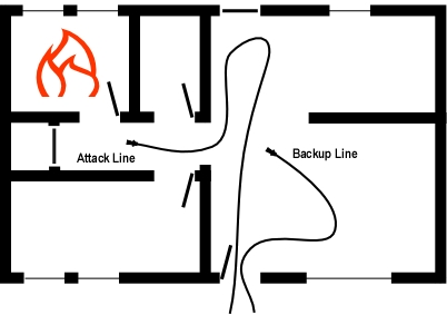
As to an answer to this problem, pulsed application does not always mean short pulses, multiple long pulses with a narrow pattern or a sweeping long pulse may be used to cover a larger area. In addition, large area compartments or open floor plan spaces may require multiple lines to adequately control the environment. The purpose of the backup line is to protect the means of egress for the attack line and this is of paramount importance in an open plan building.

The following two videos demonstrate the difference between short and long pulses. At 115 lpm (30 gpm) the flow rates in these two videos are low by North American standards, but are fairly typical for gas cooling applications in many parts of the world. Short pulses can be used effectively up to approximately 570 lpm (150 gpm) with minimal water hammer, for higher flow rates, long pulses are more appropriate.

When we do these quick bursts of fog to cool the gases we are not using much water compared to the feeling that the best way to handle this is to flow a large amount of water and basically soak the entire area down before you advance through it. I was hoping you could comment on this.

As noted in the answer to your previous question, pulses are sometimes, but not always quick. In a typical legacy residence (small compartments) short pulses are generally adequate to cool hot gases overhead. When accessing a shielded fire, and cooling the hot gases overhead it is not generally necessary to cool hot surfaces and fuel packages such as furniture (it may be a different story in the fire compartment). Water remaining on the floor or soaked into contents did not do significant work and simply added to fire control damage. We should not hesitate to use an adequate amount of water for fear of water damage, but tactical operations should focus on protecting property once (or while) we are acting to ensure the safety of occupants and firefighters.

We often enter house fires where the house is full of smoke but the smoke is not necessarily very hot. In these cases we would not normally cool the gases. From what we understand now, smoke is fuel and with open concept homes this smoke could ignite close to the fire therefore igniting the smoke nearer to us. What I was wondering is what are you teaching in regards to cooling the smoke, do you do it only when you feel a lot of heat or start cooling regardless?

As the temperature of the upper layer drops, the effectiveness of application of pulsed water fog diminishes. That said, if the upper layer is hot enough to vaporize some of the water (i.e. above 100o C), application of water will further cool the gases and provide some thermal ballast (the water will have to be heated along with the gases for ignition to occur).

When presented with cold (< 100o C) smoke, firefighters still face a hazard as gas phase fuel can still be ignited resulting in a flash fire (if relatively unconfined) or smoke explosion. The only real solution to this hazard is to create a safe zone by removing the smoke through tactical ventilation.

Mike and I will continue this dialog next week with a discussion of the protective capabilities of fog streams.

Flow Rate and Nozzle Design

Thursday, October 21st, 2010

A number of years ago, several nozzle manufacturers developed a break apart combination nozzle (shutoff separate from the tip) with an integrated solid stream tip. This design allowed the user to adjust the pattern using the combination tip, or if desired, remove the combination tip and use the nozzle to develop a solid stream. Good idea or not? On the surface this sounds like it might be a reasonable idea. The combination tip allows adjustment of the pattern while the internal solid stream may provide improved performance in penetration to reach burning fuel surfaces. In addition, if the combination tip became clogged with debris it is also possible to remove the tip and still have the capability to develop a usable fire stream.

Used on various size handlines, internal solid stream tips are generally available in sizes ranging from 7/8” to 1-1/4”. What effect does an integrated solid stream tip have on nozzle performance when a combination tip is used? Manufacturers such as Elkhart Brass and Task Force Tips warn that the integrated smooth bore tip may restrict the flow of single flow, variable flow, or automatic combination tips.

CWIFR Nozzle Tests

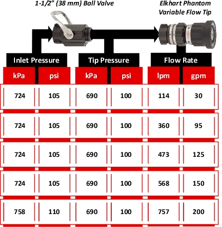
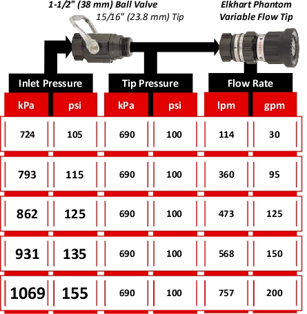
Tests conducted by Firefighter Jim Huff of Central Whidbey Island Fire & Rescue (CWIFR) demonstrate the potential friction loss impact of integrated solid stream tips. CWIFR conducted flow tests using an mid-range Elkhart Phantom tip, a 1-1/2” (38 mm) ball valve, and a 1-1/2” (38 mm) ball valve with an integrated 15/16” (23.8 mm) tip. Line gages were inserted at the base of the nozzle and between the shutoff and the tip. Nozzle inlet pressure was adjusted to maintain the designed nozzle pressure of 100 psi (690 kPa) at the tip and pressure measurements were made at each of the nozzles flow settings of 30, 95, 125, 150, and 200 gpm (114, 360, 473, 658, and 757 lpm).

As illustrated in Figure 1, the ball valve without the integrated tip had limited impact on tip pressure.

Figure 1. Full Flow Ball Valve

However, the results obtained when using a 1-1/2” (38 mm) ball valve with an integrated 15/16” (23.8 mm)solid stream tip were dramatically different. As illustrated in Figure 2, a considerably higher inlet pressure was required to provide the designed operating pressure of 100 psi (690 kPa) at the tip.

Figure 2. Ball Valve with a Solid Stream Tip

When equipped with an integrated solid stream tip, the friction loss in the nozzle shutoff is significantly impacted by tip size (the smaller the tip, the greater the friction loss at a given flow rate).

This is My Nozzle

As stated in My Nozzle:

This is my nozzle, there are many like it but this one is mine. My nozzle is my best friend. It is my life. I must master it as I master my life. Without me it is useless, without my nozzle I am useless.

I will use my nozzle effectively and efficiently to put water where it is needed. I will learn its weaknesses, its strengths, its parts, and its care. I will guard it against damage, keep it clean and ready. This I swear.

It is essential that firefighters, apparatus operators, and fire officers have an in-depth knowledge of their tools. A handline nozzle is your primary firefighting weapon in offensive firefighting operations, develop your nozzle knowledge and master this important tool.

Ed Hartin, MS, EFO, MIFireE, CFO

Gas Cooling: Part 5

Wednesday, October 6th, 2010

This is the last post in the series examining the science of gas cooling as a fire control tactic. Be forewarned, there is math ahead! I have made an attempt at providing sufficient explanation to allow firefighters, fire officers, and instructors to develop an understanding the scientific concepts underlying this fire control technique. My next post will return to the topic of extreme fire behavior and ventilation with discussion of the most recently released NIOSH report, Death in the Line of Duty 2010-10.

The Mathematical Explanation

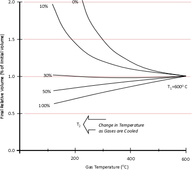
Dr. Stefan Särdqvist provides a mathematical explanation of volume changes during smoke/gas cooling In Water and Other Extinguishing Agents (Särdqvist,2002). Stefan’s text includes a graph that illustrates volume changes based on the extent to which the upper layer is cooled and the percentage of the water that is vaporized in the hot gases versus on contact with hot surfaces. As illustrated in Figure 1, the relative volume (expansion or contraction) of the upper layer during gas cooling is dependent on the percentage of water vaporizing as water passes through the hot gases of the upper layer and the percentage of water vaporizing on contact with hot surfaces such as compartment linings.

Figure 1. Volume Changes During Gas Cooling

Note: Adapted from Water and Other Extinguishing Agents (p. 155), by Stefan Särdqvist, 2002, Karlstad, Sweden: Räddnings Verket. Copyright 2002 by Räddnings Verket

If 100% of water applied for cooling vaporizes in the upper layer, the total volume of the hot fire gases and steam in the upper layer will be 79% of the original volume of the hot gases alone. If approximately 30% of the cooling water vaporizes in the upper layer and 70% vaporizes on contact with hot surfaces such as compartment linings (e.g., ceiling, walls) the volume of the upper layer will remain the same. However, if less than 30% of the cooling water is vaporized in the upper layer and the remainder is vaporized on contact with hot surfaces, the volume of the upper layer (hot fire gases and steam) will increase.

Understanding why this is the case requires a good understanding of the ideal gas law and a willingness to work through the math. As Greg Gorbett and Jim Pharr observe in the math review chapter of Fire Dynamics (2010), “The term algebra inspires dread in many otherwise competent, confident people” (p. 16).
Gas Cooling and the Ideal Gas Law

Gas Cooling: Part 4, examined the expansion ratio of steam using the Ideal Gas Law, providing a worked example to illustrate how to solve for the change in volume when water is vaporized to steam. As illustrated below, the Ideal Gas Law can also be used to determine relative influences of contraction of the upper layer and expansion of steam during gas cooling.

Before the application of water:

After the application of water:

Where:

P=Pressure (Pa)

V= Volume (m3)

T=Temperature (K)

n=Moles

Ru=Universal Gas Constant (8.3145 J/mol K)

Subscript of 1 refers to initial conditions where the upper layer consists of hot smoke and air

Subscript of 2 refers to conditions at (later) time where the upper layer consists not only to the hot smoke and air, but also to the water applied for cooling (the number of molecules in the upper layer increases, and temperature changes).

Another way of expressing the initial and final conditions using the two gas laws is to set them equal to one another:

Pressure (P) in the fire compartment and adjacent compartments remains relatively constant (due to compartment openings and other leakage). For example, the National Fire Protection Association (NFPA) Standard 92A Standard for Smoke Control Systems Using Barriers and Pressure Differences (2009) specifies a design pressure difference of 24.9 Pa (0.0036 psi) to exclude smoke from a protected area (such as a stairwell) in a non-sprinklered building with 2.7 m (9’) ceilings. As atmospheric pressure is 102325 Pa (14.7 psi) the pressure difference, while significant enough to influence smoke movement is actually quite small in most cases. Given that pressure is relatively constant and the Universal Gas Constant (Ru) is the same for all ideal gases, these factors will have the same effect on initial and final conditions (allowing both Ru and P to be factored out of the ideal gas equations used to determine changes in upper layer volume.

After factoring out Ru and P, the relationship between the upper layer volume before and after application of water is as follows:

Lots Going On!

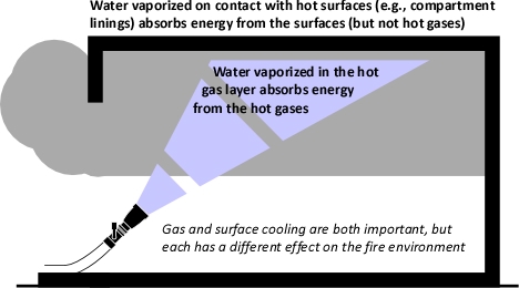
When water is applied to cool the upper layer, there is quite a bit going on. Energy is transferred from the upper layer to the water, lowering the temperature of the upper layer and raising the temperature of the water to its boiling point, vaporizing the water, and raising the temperature of the resulting steam. As the absolute temperature of the upper layer is reduced, its volume is proportionally reduced. However, as water is vaporized at its boiling point and the absolute temperature of the resulting steam is increased its volume increases. The important question is where was the water vaporized? Water vaporized in the upper layer, absorbed energy from the hot gases, lowering their absolute temperature. However, water that passes through the hot gas layer and vaporizes on contact with hot surfaces such as compartment linings (e.g., ceiling, walls) did not absorb significant energy from the upper layer and did not significantly reduce the temperature of the upper layer. Steam produced as a result of water vaporizing on contact with hot surfaces can absorb energy from the upper layer, but this has far less impact than water vaporized within the upper layer due to the large difference between the specific heat of steam and the latent heat of vaporization of water.

While some energy is lost as a result of convection of hot gases out compartment openings and conduction through compartment linings and other structural materials, these factors are not considered in this analysis of the effect of gas cooling. In this analysis the compartment defines the bounds of the thermodynamic system and the gas cooling process is considered to be adiabatic (no energy is gained or lost by the system).

Step by Step

I have made a few revisions to the explanation of gas cooling in Water and Other Extinguishing Agents (Särdqvist,2002), most significant of which is inclusion of the energy required to raise the temperature of the water applied for cooling to its boiling point (100o C). While the amount of energy is not large, this addition provides a more complete picture of the process involved in gas cooling. Other changes include consistent use of J/mol as units for specific heat and latent heat of vaporization, and minor variations in notation.

The mathematical explanation of gas cooling starts out in the same place as the concrete example provided in Gas Cooling Parts 1 and 2, determining the energy that must be transferred from the upper layer to water applied for cooling in order to achieve a specific reduction in temperature and the amount of water required to accomplish this. However, unlike an example using a specific compartment in which the units for specific heat and latent heat of vaporization were J/kg, the mathematical explanation uses J/mol (the reason for this will become clear as we dig a bit deeper).

The relationship between J/mol and kJ/kg as units of measure for specific heat and latent heat of vaporization is fairly straightforward as illustrated below:

The following equation explains the energy balance between hot gases in the upper layer and water applied for cooling. At first glance, this equation seems extremely complex, but if each segment is examined individually, it is fairly straightforward.

Where

Cp,g=Specific heat capacity of fire gases/smoke (approximately the same as air, 33.2 J/mol K at 1000 K).

Cp,st=Specific heat capacity of steam (41.2 J/mol K at 1000 K)

Cp,w=Specific heat capacity of water (76.663 J/mol K at 215.15 K)

LV,w=Latent heat of vaporization of water 40,680 J/mol

Tu=Temperature of the upper layer (K)

Tw=Temperature of water (K)

n=Moles

Subscript of 1 refers to initial conditions

Subscript of 2 refers to conditions at (later) time 2

First examine the left side of the equation which deals with the hot gases in the upper layer.

The left side of the equation determines the energy that must be transferred from the hot gases in the upper layer in order to result in a specific reduction in temperature. As this example does not deal with a specific compartment, the mass of the upper layer is unknown. A challenge resolved through the use of moles to define the amount of hot fire gases present in the upper layer. Remember that moles are a measure of the number of molecules present.

Multiplying the molar specific heat of smoke (Cp,g) in J/mol K by the number of moles (n) determines the energy that must be transferred from the upper layer to change its temperature 1 K. Multiplying that value by the change in absolute temperature (T1-T2) determines the total energy that must be transferred to achieve the specified change in absolute temperature.

Now examine the right side of the equation which deals with the water applied for cooling:

The right side of the equation determines the energy that must be transferred to the water applied for cooling in order to increase the temperature of the water (as steam) by the same extent as the reduction in upper layer temperature.

The first step is to determine the amount of water applied (remember the assumption that all water applied is vaporized either in the gas layer or on contact with surfaces). This is accomplished by subtracting the amount of hot gases in the upper layer (in Moles) from the amount of hot gases, and steam in the upper layer after cooling the gases (n2 – n1).

When vaporized in the upper layer, energy is transferred from the hot gases in the upper layer to 1) raise the temperature of the water to its boiling point of 373.15 K (100o C), 2) to change its state from liquid phase to gas phase, and 3) to raise the temperature of the steam until reaching equilibrium (hot gases and steam are at the same temperature). When water is vaporized on contact with a hot surface, it did not absorb significant energy while traveling through the hot gasses of the upper layer. The energy necessary to raise the temperature of the water to its boiling point and vaporize it is absorbed from the surface. Steam produced in this manner will also absorb energy from the hot gases of the upper layer (but the process of increasing the temperature of the water in liquid form and vaporization did not take significant energy from the hot gasses of the upper layer).

Figure 2. Gas Versus Surface Cooling

As water that is vaporized in the upper layer absorbs energy from the hot gases to raise its temperature to boiling and vaporize.

The temperature increase required for water to reach its boiling point is determined by subtracting the initial temperature of the water (Tw,1) from its boiling point of 373.15 K. The increase in the temperature of the water in liquid form is multiplied by the specific heat of water (Cp,w) to calculate the total energy required for this temperature increase (Cp,w (373.15- Tw,1)).

The latent heat of vaporization (LV,w) is added to the energy required to raise the temperature of the water from Tw1 to its boiling point of 373.15 K (100o C).

After water is vaporized (either while traveling through the upper layer or on contact with a hot surface) it continues to absorb energy from the upper layer until the temperature of the steam and the hot gases in the upper layer reach the same temperature and are in thermal equilibrium. The specific heat of steam (Cp,w) is multiplied by the difference between 373.15 K (100o C) and the final temperature of the upper layer (Tu2). This determines the energy required for the steam and the hot gases in the upper layer to reach thermal equilibrium ( ).

As with the calculations examining the smoke and hot gases in the upper layer, moles are a measure of the amount of water applied for cooling. As the thermodynamic system of the compartment is being treated as adiabatic (no energy leaves the system, it is simply transferred between the hot gases of the upper layer and the water applied for cooling), the left and right sides of the equation must be equal.

Solving for n, this equation may also be written:

Given that:

The left side of the equation can be simplified to solve for the amount of molecules in the upper layer before cooling (n1) and after application of water (n2) as follows:

Solving for n allows the energy exchange equation to be combined with the two ideal gas laws used to describe changes in volume associated with gas cooling.

As the energy exchange equation is equal to the initial amount of gas molecules in the upper layer before gas cooling divided by the amount of gas molecules in the upper layer after the application of water, the energy balance equation can be inserted in the ideal gas law in place of the amount of molecules (n1 and n2) as illustrated below:

This formula looks quite complex, but in actuality most of the values are constants such as the specific heat of water (Cp,w), latent heat of vaporization of water (LVw), and specific heat of steam (Cp,st). After plugging in these constants, the only variables on the right side of the equation are the temperature of the upper layer before and after cooling and the percentage of water vaporized in the upper layer.

The volume of the upper layer after cooling divided by the volume of the upper layer before cooling is the percentage change in volume of the upper layer.

Worked Examples

While explaining the equations is important, there is nothing quite so useful in developing understanding as actual worked examples. In each of these examples, the initial upper layer temperature is 773.15 K (500o C), the initial temperature of the cooling water is 293.15 K (20o C) and the final temperature of the upper layer is 473.15 K (200o C).

Example 1: All (100%) of the water applied for cooling is vaporized in the upper layer.

In this example where all of the water applied for cooling is vaporized in the upper layer, the volume of the upper layer is reduced by 27% and the lower boundary of the upper layer would rise. This illustrates the ideal (but likely not achievable) application of gas cooling to reduce temperature and raise the lower boundary of the upper layer.

Example 2: None (0%) the water applied for cooling is vaporized in the upper layer; all of it is vaporized on contact with hot compartment linings or other surfaces.

In this example where none of the water applied for cooling is vaporized in the upper layer, but vaporizes on contact with hot surfaces, the volume of the upper layer would double. If the upper layer filled more than half the volume of the compartment, the upper layer would then fill the entire compartment with hot gases and steam at 473.15 K (200o C), providing an untenable environment for both firefighters and trapped occupants. This is why an indirect attack is not used from inside the compartment or in compartments where there may be savable victims.

Example 3: One third (33.3%) of the water applied for cooling vaporizes in the upper layer and the remainder (66.6%) is vaporized on contact with hot compartment linings or other surfaces.

In this example, the volume of the upper layer is unchanged, but considerably cooler than before the application of water. If firefighters had adequate working area below the upper layer before applying cooling water, this would be unchanged, but the temperature of the gases overhead would be considerably reduced. With good technique and an appropriate flow rate, more than 33.3% of the water applied for cooling can be vaporized in the upper layer, providing practical results somewhere between a 3% (Example 3) and 27% (Example 1) reduction in the volume of the upper layer. However, it is important to remember that the fireground is much more dynamic than the simple analysis presented in this post.

Different Parts of the Elephant

Firefighter’s perspectives on the use of water fog for interior structural firefighting can be compared to the Indian fable of The Six Blind Men and the Elephant (Saxe, 1963). In this fable, the six men tried to determine what an elephant was. As none of the men could see, they used their sense of touch. However, each grasped a different part of the elephant. One touched the side and thought an elephant was like a wall, another the trunk and thought an elephant was like a snake, and so forth. What you believe may be limited by your point of observation.
Many firefighters in the United States find it hard to believe that the volume of the upper layer can be reduced and the bottom of the upper layer raised by application of water. This is inconsistent with their experiences in the field. The explanation provided in this post illustrates how this is possible. If flow rate and application technique used result in more than 70% of cooling water vaporizing on contact with hot surfaces, the upper layer will increase in volume and the level of the hot gas layer in a confined area such as a compartment will become lower (consistent with many firefighters experience when using water fog for interior structural firefighting). However, this does not have to be the case. Where the water is vaporized and the resulting effects are dependent on application technique, flow rate, and duration of application!

I would like to extend a great deal of thanks to Stefan Särdqvist for providing the basis for this explanation and to Lieutenant Felipe Baeza Lehnert of Valdivia (Chile) Fire Department Company 1 (Germania) for his patience in helping me sort though the math.
Ed Hartin, MS, EFO, MIFireE, CFO

References

National Fire Protection Association (NFPA). (2009). Standard 92A Standard for Smoke Control Systems Using Barriers and Pressure Differences. Quincy, MA: Author.
Saxe, J. (1963). The blind men and the elephant. New York: McGraw-Hill

Särdqvist, S. (2002) Water and other extinguishing agents. Karlstad, Sweden: Räddnings Verket

Gas Cooling: Part 3

Sunday, September 5th, 2010

The first post in this series, Gas Cooling, began the process of providing a conceptual explanation of the fire control technique of gas cooling. As previously discussed, gas cooling reduces the hazards presented by the upper layer in a compartment fire by cooling hot gases and reducing the potential that they will ignite. Water is an effective fire control agent for this purpose because a tremendous amount of energy is required to raise its temperature and vaporize it at its boiling point.

Gas Cooling: Part 2 identified the amount of water that is theoretically necessary to cool the upper layer of a compartment containing 40 m3 (4 m wide  x 5 m long x 2 m deep) from 500o C (932o F) to 100o C (212o F). In addition, this post identified practical limitations with the efficiency of typical combination nozzles used and determined the duration of application necessary to cool the upper layer to 100o C (212o F) at different flow rates.

This raises the question, what would happen if you didn’t apply sufficient water to cool the upper layer to 100o C (212o F)?

What If?

Steam continues to absorb energy if its temperature is increased above 100o C (212o F). Some firefighters are under the impression that you cannot have steam at a temperature above 100o C (212o F) at normal atmospheric pressure. This is incorrect. Water (in liquid form) will not increase above 100o C (212o F) as this is it’s boiling point at normal atmospheric pressure, but steam acts as any other substance in the gaseous form and can increase in temperature beyond that which it changed phase from liquid to gas.

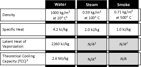
Figure 1. Properties of Water, Steam, & Smoke

Properties of Water, Steam, and Smoke

1 100 kg/M3 =1 kg/l

2 Not applicable as smoke and steam are in the gas phase

3 TCC is based on heating water from 20o C to 100o C and conversion to steam

4 Steam will continue to absorb energy until reaching temperature equilibrium

As illustrated in Figure 1, a kilogram of steam (slightly under 1.69 m3 at 100o C) will absorb 2.0 kJ of energy for each oC that the temperature of the steam is increased. The temperature of steam will continue to increase as long as the surrounding gases and/or surfaces that it is in contact with are of higher temperature. This process will continue until the steam, gases, and surfaces that the steam is in contact with reach equilibrium (i.e., the same temperature).

So even if insufficient water is applied to lower the temperature of the upper layer to 100o C (as described in Gas Cooling: Part 2 [LINK]), the combined effects of heating and vaporizing the water (the major cooling mechanism) and heating the steam produced to a temperature higher than 100o C (212o F), can have a significant cooling effect. This effect is often sufficient to extinguish flames in the upper layer and slow or reduce pyrolysis caused by heating of fuel packages due to radiative and conductive heat transfer from the flames and hot gases in the upper layer.

Gas Laws

When water as a liquid is vaporized to form steam, it expands and becomes less dense. Fire service texts such as the 5th Edition of the Essentials of Firefighting (IFSTA, 2008) commonly state that the volume of water expands 1700 times when it is converted to steam at 100o C (212o F). These texts state this as a fact to be memorized, but do not explain why this is the case or that if temperature is increased further, that the volume of steam will continue to expand. While having a number of different characteristics as illustrated in Figure 1, steam and smoke are both in the gas phase, they behave somewhat similarly. In chemistry and physics, the behavior of gases is described by a number of physical laws collectively described as the gas laws. Understanding the gas laws provides an explanation of why smoke and the steam produced during firefighting operations behave the way in which they do.

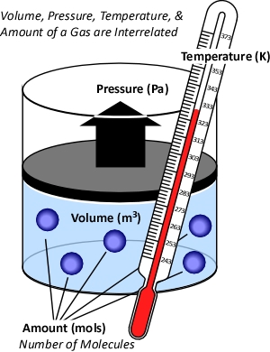
While gases have different characteristics and properties, behavior of gases can be described in general terms using the ideal gas law. This physical law describes the relationship between absolute temperature, volume, and pressure of a given amount of an ideal gas.

Figure 2. Temperature, Volume, Pressure & Amount

The concept of an ideal gas is based on the following assumptions:

  • Gases consist of molecules in random motion
  • The volume of the molecules is negligible in comparison to the total volume occupied by the gas
  • Intermolecular forces (i.e., attractive forces between molecules) are negligible
  • Pressure is the result of gas molecules colliding with the walls of its container

The ideal gas law is actually a synthesis of several other physical laws that each describes a single characteristic of the behavior of gases in a closed system (enclosed in some type of container). Of these gas laws, Charles’s Law provides the simplest explanation of the phenomena that occur during gas cooling.

Charles’s Law: In the 1780s, French scientist Jacques Charles studied the effect of temperature on a sample of gas at a constant pressure. Charles found that as the gas was heated, the volume increased. As the gas was cooled, the volume decreased. This finding gave rise to Charles’s Law which states that at a constant pressure the volume of a given amount (mass or number of molecules) of an ideal gas increases or decreases in direct proportion with its absolute (thermodynamic) temperature. The symbol  is used to express a proportional relationship (much the same as = is used to express equality), so this relationship can be expressed as:

Where:

V=Volume

T=Temperature

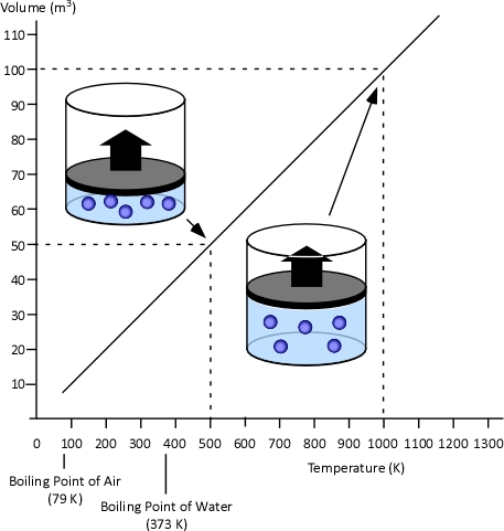
When two values (such as volume and temperature in Charles’s Law) are proportional, one is a consistent multiple of the other. For example If one value was consistently eight times the other, the values would also be proportional. In the case of Charles’s Law when the absolute temperature of a gas doubles, the pressure doubles. Figure 3 illustrates the relationship between absolute temperature in Kelvins (K) and volume in cubic millimeters (mm3).

Figure 3. Charles’s Law

This relationship can also be stated using the following equation:

Where

V=Volume

T=Temperature

Subscript of 1 refers to initial conditions

Subscript of 2 refers to final conditions

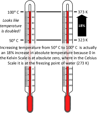
It is important to remember that absolute temperature is measured in Kelvins (K), not degrees Celsius or Fahrenheit, because the Kelvin scale places the zero point at absolute zero, so that doubling the temperature in K, is actually doubling the temperature. As illustrated in Figure 4, the same does not hold true when using the Celsius scale (the Fahrenheit scale presents the same problem).

Figure 4. Absolute Temperature

Application of Charles’s Law provides a simple approach to examining the question of why application of water into the upper layer does not necessarily result in an increase to upper layer volume (by adding steam) and increasing its thickness (with the bottom of the layer moving closer to the floor). This requires the assumption that while the higher temperature inside the fire compartment results in increased pressure, this increase is fairly small and does not have an appreciable outcome on volume changes during gas cooling.

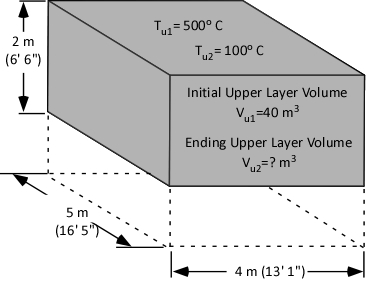
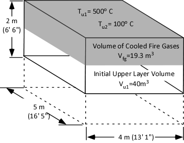
As a first step in answering the question, consider what is known at this point (as illustrated in Figure 5):

  • The initial volume of the upper layer (Vu1) is 40 m3.
  • The initial temperature of the upper layer (Tu1) is 500o C (932o F)
  • The ending temperature of the upper layer (Tu2) is 100o C (212o F)

The answer we are in search of is the ending volume of the upper layer (Vu2), the volume of fire gases (Vfg) plus the volume of steam produced (Vst) during application of water for gas cooling.

Figure 5. Compartment Temperature and Volume

Expanding Steam

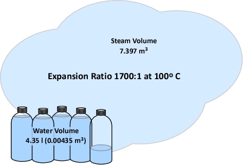
As discussed in Gas Cooling: Part 2 [LINK], 4.35 kg (4.35 l) of water must be vaporized in the upper layer in order to lower the temperature to 100o C (212o F). The volume of water in liters must be converted to cubic meters (the same units of measure used for the volume of the compartment and upper layer). A liter is 0.001 m3, so 4.35 l equals 0.00435 m3. For now, we will accept that conversion of water to steam results in a 1700:1 expansion ratio (a later post in this series will explain why). With an expansion ratio of 1700:1, 0.00435 m3 of water expands to 7.395 m3 of steam at 100o C (212o F) (see Figure 6)

Figure 6. Expansion of Steam at 100o F

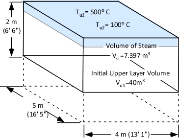
Figure 7 illustrates the volume of steam produced when 4.35 l of water is vaporized in the upper layer of the example compartment relative to the initial volume of the upper layer.

Figure 7. Steam Expansion in a Compartment

Contracting Upper Layer

Why doesn’t the 7.397 m3 of steam that results from vaporization of the 4.35 liters of water applied for gas cooling simply increase the volume of the upper layer by 7.397 m3? Charles’s law provides the key. Charles’s Law indicates that as a gas is heated its volume will increase in direct proportion to the increase in its absolute temperature. However, the reverse is also true. The volume of a gas will decrease in direct proportion to the decrease in its absolute temperature.

Cooling the upper layer from 500o C (932o F) to 100o C (212o F) results in a 52% decrease in absolute temperature from 773 K to 373 K. The volume of the upper layer which was initially 40 m3 is reduced in direct proportion to the reduction in absolute temperature.

The volume of the upper layer (fire gases) after cooling from 500o C (932o F) to 100o C (212o F) can be calculated by solving for Vu2:

Reduction in temperature from 500o C (932o F) to 100o C (212o F) results in reduction of the volume of fire gases from 40m3 to 19.3 m3 as illustrated in Figure 8.

Figure 8. Contraction of the Upper Layer

Putting it All Together

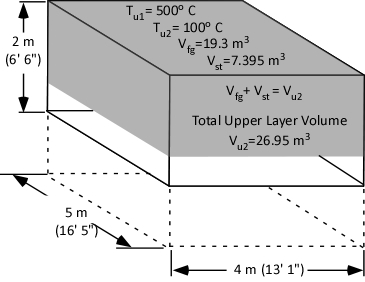
If the water applied to cool the upper layer expands to form 7.395 m3 of steam and the final volume of the cooled upper layer is 19.3 m3, the total upper layer volume is 26.95 m3.

Figure 8. Total Upper Layer Volume

<

Dividing the Total Upper Layer Volume (Vu2) of 26.95 m3 by the area of the compartment (20 m2) determines the depth of the upper layer as being 1.347 m. Therefore, cooling the upper layer from 500o C (932o F) to 100o (212o F) C will cause the bottom of the upper layer to rise 0.6525 m (2.1’).

The Short Answer

The following points summarize the last three posts dealing with gas cooling as a fire control technique:

  • The volume of water required to cool the upper layer is quite small due to its specific heat and latent heat of vaporization in its liquid form and the specific heat of steam.
  • The expansion ratio of steam at 100o C (212o F) is 1700:1, but as the volume of water used to cool the upper layer is small, the expanded volume is still relatively small (in comparison to the contraction of the upper layer).
  • In the process of reaching equilibrium, the temperature of the upper layer is reduced to a greater extent than the temperature of the water increases due to the cooling capacity of the water and the relatively low specific heat of fire gases and air.
  • The large temperature drop in the upper layer results in a proportional reduction in volume (which works out be greater than the increase in volume resulting from the expansion of steam from water vaporized in the hot gas layer for cooling).

Based on each of these factors, a small amount of water can cool the upper layer and reduce its volume, resulting in the lower boundary of the upper layer rising as its depth decreases.

A Few Little Wrinkles!

The preceding example may conflict with your personal experience. Many of us have been in a hot, smoke filled compartment and had steam and smoke bank down on top of us after application of water. Why might this be the case?

The outcome of the preceding example depends on all of the water being vaporized while traveling through the upper layer. In this case, energy to vaporize the water is transferred from the hot gases in the upper layer, cooling the layer and causing it to contract. If the water passes through the upper layer without vaporizing, the temperature of the upper layer is not reduced and it does not contract. Water vaporizing on contact with hot compartment linings results in the steam produced being added to the volume of the upper layer. This steam cools the upper layer to some degree, but far less than using the energy of the hot gases to vaporize the water as it passes through the upper layer (compare the specific heat of steam to the specific heat and latent heat of vaporization of water in Figure 1).

When applying water fog into the upper layer, some of the water vaporizes as it travels through the hot gases and some reaches the compartment linings. Determining changes in the volume of the upper layer under these conditions is a bit more complex and requires a deeper examination of the gas laws.

Continuing the Discussion

The next post in this series will examine the other gas laws that lead to the development to the Ideal Gas Law and how this law can be used to answer questions about changes in upper layer volume as a result of gas cooling under a variety of different conditions.

Spanish Translation of Effective and Efficient Fire Streams

Thanks to Firefighters Tomá Ricci and Martín Comesaña from San Martín de Los Andes, Argentina for translating the series of posts on Fire Stream Effectiveness and Efficiency into Spanish. They can be downloaded in PDF format:

Ed Hartin, MS, EFO, MIFireE, CFO

References

International Fire Service Training Association (IFSTA). (2008). Essentials of firefighting (5th ed). Stillwater, OK: Fire Protection Publications.

Gas Cooling: Part 2

Sunday, August 22nd, 2010

In a compartment fire, the upper layer can present significant hazards to firefighters, including potential for ignition and energy transfer). My last post, Gas Cooling, began an examination of the science behind gas cooling, application of water fog into the upper layer to reduce the potential for ignition and thermal hazards presented by the hot gases.

Figure 1. Energy Transfer Required for Cooling

With a specific heat of 4.2 kJ/kg and latent heat of vaporization of 2260 kJ/kg, it takes considerable energy to raise the temperature of water to its boiling point of 100o C and change it from liquid to gas phase steam. Smoke on the other hand has a specific heat of 1.0 kJ/kg, indicating that in comparison with water; much less energy is required to change its temperature. As explained in Gas Cooling, 11.3 MJ must be transferred from the upper layer of this compartment to water applied for cooling in order to lower the temperature of the upper layer in a compartment from 500o C to 100o C (see Figure 1). It is important to remember that the energy required to cool the upper layer is dependent on the mass of hot smoke and air in the upper layer. This value will vary with the size of the compartment and the temperature of the hot gases.

When starting out on this examination of gas cooling, we posed two questions:

  • How much water is required to cool the upper layer from 500o C to 100o C?
  • Why doesn’t the volume of the upper layer increase when water applied to cool the hot gases is turned to steam?

The answers to these questions are interrelated. First, let’s look at the amount of water required.

Water Required for Cooling

When water is applied for fire control and extinguishment, energy is transferred from materials that have a temperature higher than that of the water to raise the temperature of the water and to change it from liquid phase to gas phase.

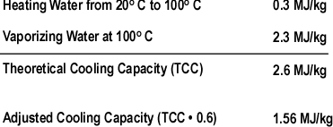
The theoretical cooling capacity (TCC) of water is 2.6 MJ/kg. This value is based on heating a kilogram of water from 20o C to 100o C (0.3 MJ/kg) and vaporizing it completely into steam (2.3 MJ/kg).

Dividing the energy that must be transferred from the upper layer by the TCC calculates the amount of water that would theoretically be required to cool the upper layer from 500o C to 100o C if the energy transfer and conversion of water to steam was 100% efficient. If this was the case, the upper layer could be cooled to 100o C by applying 4.35 kg of water. Given the density of water at 20o C of approximately 1.0 kg/l, this would be a volume of approximately 4.35 liters. However, this assumes instantaneous heat transfer and 100% efficiency in conversion of water to the gas phase. Neither of which is possible in the real world!

Experimental data (Hadjisophocleous & Richardson, 2005; Särdqvist, S., 1996) has shown that the cooling efficiency of water in both laboratory experiments and actual firefighting operations ranges from 0.2 to 0.6. Särdqvist (1996) suggests that an efficiency factor of 0.2 be used for interior fog nozzles. Barnett (as cited in Grimwood, 2005) suggests that an efficiency factor of 0.5 be used for solid or straight stream application and 0.75 for fog application. In actuality, the efficiency of water application varies considerably with the design of the nozzle, skill of the nozzle operator, and a range of other factors. For our examination of gas cooling, we will use an efficiency factor of 0.6 (60%).

Multiplying the TCC of water by 0.6 adjusts the cooling capacity to account for the fact that some of the water applied into the hot gas layer will not turn to steam while passing through the hot gas layer. Some of the droplets will pass through the gas layer and vaporize on contact with hot surfaces (more on this later) and others will fall to the floor, with increased temperature, but remaining in liquid form.

Figure 2. Adjusted Cooling Capacity of Water

Dividing the 11.3 MJ of energy that must be transferred from the upper layer of the compartment by an Adjusted Cooling Capacity (ACC) of 1.56 MJ/kg determines that 7.2 kg (7.2 liters) of water are required to lower its temperature from 500o C to 100o C.

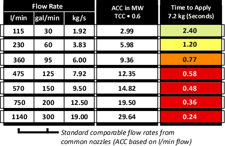
Figure 3 illustrates common flow rates from combination nozzles, Adjusted Cooling Capacity (ACC) and time required to apply the 7.2 kg of water necessary to cool the upper layer of the compartment from 500o C to 100o C.

Figure 3. Flow Rate, Adjusted Cooling Capacity, and Application Duration

As illustrated in Figure 3, if water is applied at 115 l/min (30 gal/min), several short pulses will provide sufficient water application. If the flow rate is increased to 230 l/min, a single pulse is likely to be sufficient. However, if the flow rate is increased further, it is likely that excessive water will be applied. In addition, droplet size increases with flow rate, reducing efficiency.

All Models are Wrong!

This examination of gas cooling provided a simple example of how much water is required to cool the upper layer in a given compartment. While this explanation provides a good way to understand how gas cooling works, it is incomplete. Box and Draper (1987, p. 424)observe that “all models are wrong, but some are useful”. The following factors add quite a bit of complexity to examination of gas cooling:

  • The energy that must be transferred from the upper layer is dependent on the mass of the hot gases and their temperature.
  • Not all of the water applied vaporizes in the upper layer (some droplets travel through the hot gases and vaporize on contact with hot surfaces and others drop to the floor without completely vaporizing).
  • Temperature of the hot gases in the upper layer is not uniform (as assumed in two layer models).
  • Ongoing combustion and energy transfer from hot compartment linings add energy to the hot gas layer.
  • Convection and gravity current influence the movement of hot and cool gases, making conditions dynamic rather than static.

While our model of gas cooling is wrong, I believe that it is useful. Firefighters do not calculate the volume of water required to cool the hot gas layer on the fireground. However, it is important to understand how flow rate and duration impact on effectiveness and efficiency.

Important!

Remember that this example involved gas cooling in a single compartment with static conditions. The flow rate and/or duration of application for fires in larger compartments or direct attack on burning fuel may be quite different.

What’s Next?

One question remains in our examination of gas cooling. Why doesn’t the volume of the upper layer increase when water applied for gas cooling turns to steam? This will be the focus of the third post in this series.

Ed Hartin, MS, EFO, MIFireE, CFO

References

Box, G. & Draper, R (1987). Empirical Model-Building and Response Surfaces. New York: Wiley.

Hadjisophocleous, G.V. & Richardson, J.K. (2005). Water flow demands for firefighting. Fire Technology 41, p. 173-191.

Särdqvist, S. (1996) An Engineering Approach To Fire-Fighting Tactics Sweden, Lund University, Department of Fire Safety Engineering

Svennson, S. (2002). The operational problem of fire control (Report LUTVDG/TVBB-1025-SE). Sweden, Lund University, Department of Fire Safety Engineering.

Grimwood, P. (2005). Firefighting Flow Rate: Barnett (NZ) – Grimwood (UK) Formulae. Retrieved January 26, 2008 from http://www.fire-flows.com/FLOW-RATE%20202004.pdf

Gas Cooling

Saturday, August 14th, 2010

In a compartment fire, the upper layer presents a number of hazards to firefighters including the fact that 1) Smoke is fuel, and 2) the upper layer can be extremely hot. Application of an appropriate amount of water fog into the upper layer reduces the potential for ignition and lowers the temperature of the gases (reducing thermal load on the firefighters working below). While this sounds simple, and fairly intuitive, this basic technique to control upper layer hazards is frequently misunderstood. This is the first in a series of posts that will attempt to provide a simple explanation of the science behind gas cooling as a fire control technique.

How Does it Work

When a pulse (brief application) of water fog is applied into a layer of hot smoke and gases with a temperature of 500o C (932o F) what happens? As the small droplets of water pass through the hot gas layer, energy is transferred from the hot smoke and gases to the water. If done skillfully, the upper layer will not only be cooler and lest likely to ignite, but it will contract (or at least stay the same volume) providing a safer working environment below.

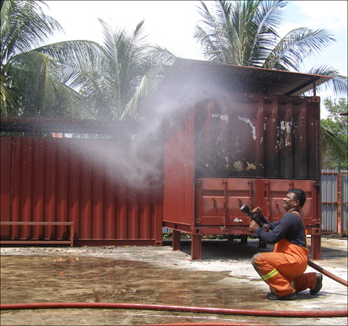
As demonstrated by Superintendent Rama Krisana Subramaniam, Bomba dan Penelamat (Fire & Rescue Malaysia) a short pulse can place a large number of small water droplets in the upper layer that develops during a compartment fire (see Figure 1).

Figure 1. Short Pulse

When presenting this concept, firefighters often present me with two questions:

  • Since water expands approximately 1700 times when turned to steam at 100o C, why doesn’t the upper layer drop down on top of the firefighters?
  • How can such a small amount of water have such a dramatic effect on the fire environment?

Math or No Math?

Using a bit of math, there is a really good explanation as to how gas cooling really works. The best answer is a bit complex, but a good conceptual explanation can be accomplished with a minimal amount of math.

Heating the water to 100o C (212o F) and production of steam transfers a tremendous amount of energy from the hot smoke and gases to the water, reducing the temperature of the hot gases. As the temperature of the hot gases is reduced so is their volume. However, don’t forget about the steam.

When water is turned to steam, it expands. At its boiling point, water vaporized into steam will expand 1700 times. A single liter of water will produce 1700 liters (1.7 m3) of steam. The expansion ratio when water is vaporized is significant. However, due to the tremendous amount of energy required to vaporize the water (and resulting reduction in gas temperature), the final volume of the mixture of hot gases and steam is less than the original volume of hot gases within the compartment.

The Key

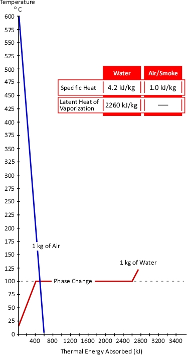
The temperature of the gases is lowered much more than the temperature of the water is increased. Why might this be the case? The key to this question lies in the concepts of specific heat and latent heat of vaporization. As illustrated in Figure 2, the specific heat of smoke is approximately 1.0 kJ/kg (Särdqvist, 2002; Yuen & Cheung, 1999) while the specific heat of water is 4.2 kJ/kg and even more importantly the latent heat of vaporization of water is 2260 kJ/kg. What this means is that it requires over four times the energy to raise the temperature of a kilogram of water by 1o C than it does to lower the temperature of smoke by the same amount. In addition, it requires 2260 times the energy to turn 1 kg of water to steam at 100o C than it does to lower the temperature of 1 kg of smoke by 1o C.

Figure 2. Heating and Cooling Curves of Smoke & Water

While water expand as it turns to steam, the hot gas layer will contract as it’s temperature drops. At the same pressure, change in the volume of a gas is directly proportional to the change in absolute temperature. If the initial temperature of the hot gas layer is 500o C (773 Kelvin) and its temperature is lowered to 100o C (373 Kelvin) the absolute temperature is reduced by slightly more than half (773 K-373 K=400 K). Correspondingly the volume of the hot gases will also be reduced by half.

An Example

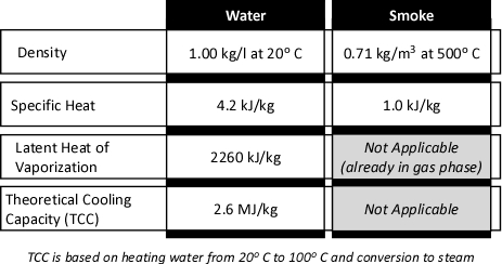
Once the underlying concept of gas cooling has been explained, the question of how a small amount of water can have such a dramatic effect may still remain. After all, the preceding explanation compared a kilogram of water to a kilogram of air. Firefighters normally do not usually think of either of these substances in terms of mass. Water is measured in liters or gallons. If measurement of smoke and air is thought of, it would likely be in cubic meters (m3) or cubic feet (ft3). Sticking with SI units, consider the properties of water and smoke as illustrated in Figure 3:

Figure 3. Properties of Water and Smoke

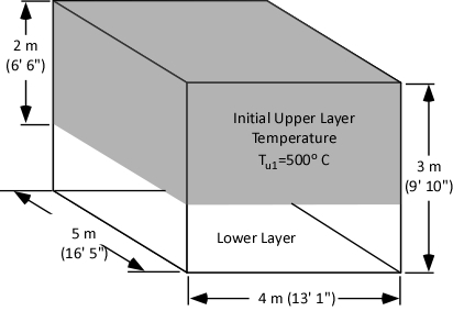
While over simplified, the compartment fire environment can be considered as being comprised of two zones; a hot upper layer and a cooler lower layer, each with reasonably uniform conditions (this is the approach used by computer models such as the Consolidated Model of Fire and Smoke Transport, CFAST).

As illustrated in figure 4, our examination of gas cooling will consider a single compartment 4 meters (13’ 1”) wide and 5 meters (16’ 5”) long with a ceiling height of 3 meters (9’ 10”). The upper layer comprised of hot smoke and air is two meters deep and has an average temperature of 500o C (932o F).

Figure 4. Compartment with Two Thermal Zones

What volume of water must be applied into the upper layer to reduce its temperature from 500o C to 100o C?

Just as input of energy is required to increase temperature, energy must be transferred from a substance in order to lower its temperature. The first step in determining the water required for cooling is to calculate the energy that must be transferred from the upper layer to achieve the desired temperature reduction.

The specific heat of smoke is approximately 1.0 kJ/kg. This means that 1.0 kJ of energy must be transferred from a kilogram of smoke in order to reduce its temperature by 1o C. This requires that we determine the mass of the upper layer.

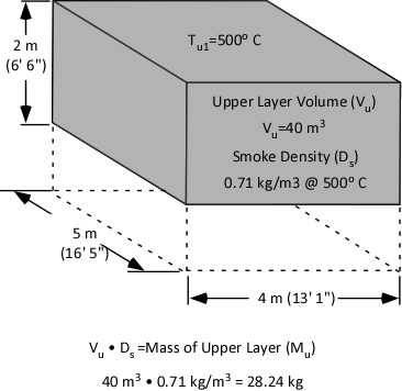
Calculation of mass involves multiplying the volume of the upper layer (40 m3) by the (physical) density of smoke (0.71 kg/m3) at the average temperature of the upper layer (500o C) as illustrated in Figure 5.

Figure 5. Mass of the Upper Layer

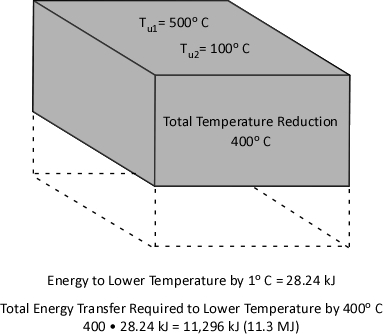
Specific heat is the energy required to raise the temperature of a given unit mass of a substance 1o. The same energy must be also be transferred to lower the temperature of a unit mass of a substance by 1o. As illustrated in Figure 3, the specific heat of smoke is 1.0 kJ/kg. Therefore, to lower the temperature of a single kilogram of smoke by 1o C, 1.0 kJ must be transferred from that kilogram of smoke. With an upper layer mass (Mu) of 28.24 kg, 28.24 kJ must be transferred from the upper layer to water applied for gas cooling in order to reduce its temperature by 1o C.

Reduction of upper layer temperature from 500o C to 100o C is a change of 400o. Multiplying 28.24 kJ by 400 determines the total amount of energy that must be transferred to water applied for gas cooling in order to reduce the temperature to 100o C. As illustrated in Figure 6, 11,296 kJ (11.3 MJ) must be transferred from the upper layer to the water to effect a 400o C reduction in temperature.

Figure 6. Energy Transfer Required

Now that we have determined the energy that must be transferred from the upper layer in order to lower the temperature from 500o C to 100o C, it is possible to identify how much water must be applied to accomplish this task. However, that will be the topic of my next post. In addition, I will provide an explanation as to why the volume of the upper layer does not (necessarily) increase when water applied to cool the gases turns to steam.

Ed Hartin, MS, EFO, MIFireE, CFO

References

Särdqvist, S. (2002). Water and other extinguishing agents. Karlstad, Sweden: Räddnings Verket.

Yuen, K. & Cheung, T. (1999). Calculation of smoke filling time in a fire room – a simplified approach. Journal of Building Surveying, 1(1), p. 33-37

Nozzle Evaluation

Sunday, March 28th, 2010

As with many other questions, it is likely that the answer to the question of which nozzle is best is it depends. As discussed in Effective and Efficient Fire Streams, Safe, effective and efficient fire control requires:

  • Water application to control the fire environment as well as direct attack on the fire
  • Appropriate flow rate for the tactical application (cooling hot, but unignited gases may be accomplished at a lower flow rate than direct attack on the fire)
  • Direct attack to exceed the critical flow rate based on the fires heat release rate
  • Sufficient reserve (flow rate) be available to control potential increases in heat release rate that may result from changes in ventilation
  • Water application in a form appropriate to cool its intended target (i.e., small droplets to cool hot gases or to cover hot surfaces with a thin film of water)
  • Water to reach its intended target (fog stream to place water into the hot gas layer and a straight or solid stream to pass through hot gases and flames and reach hot surfaces)
  • Control of the fire without excessive use of water

Accomplishing this requires different stream characteristics at different times. The characteristics that are optimal for gas cooling are likely quite different than for cooling hot surfaces, particularly when dealing with fully developed fire conditions in a large compartment. It is likely that direct attack on a fire with a high heat release rate in a large compartment may best be accomplished with a high flow stream having a high degree of stream cohesion and extremely large droplets. On the other hand, cooling the hot gas layer while accessing a shielded fire is most effectively and efficiently accomplished using a fog stream with a variable pattern angle, small droplet size, and a lower flow rate. No nozzle and hose system will be equally effective and efficient in all situations.

At present, there is no standardized method for testing and evaluating the effectiveness and efficiency of firefighting nozzles. However, there are a number of parameters that may be useful in the process of evaluating, selection, and specification of combination nozzles.

Application

Nozzle selection must be considered within the context of the nozzle, hose, and pump system that it will be used. If starting from scratch, it may be useful to consider each of these components. For example, high and ultra high pressure systems can provide considerably higher efficiency than low pressure systems, but they are limited to low flow rates. Low pressure systems on the other hand have larger droplet sizes and as such cannot achieve as high efficiency as higher pressure systems, but are scalable to deliver higher flow rates. If we have an existing system in place, the question may be what nozzle will provide the greatest effectiveness, efficiency, and range of capabilities.

It is also important to consider the type of buildings and occupancies in which firefighting operations will likely take place. Important factors include building and interior compartment size and occupancy. Another factor that must be considered is pressure limitations imposed by fixed fire suppression systems such as standpipes (in some cases outlet pressure is limited to 65 psi (448 kPa).

While there is no standard test methodology for determining the effectiveness and efficiency, there are a number of characteristics that can be assessed and evaluated when considering selection and specification of the handline nozzles.

Starting Point

Central Whidbey Island Fire & Rescue (CWIFR), where I serve as Fire Chief is about to start the process of evaluating nozzles for use on existing 1-3/4 (45 mm) handlines. CWIFR is a small fire district with a mix of residential and commercial occupancies located approximately 60 miles (97 km) north of Seattle, Washington. Structural fire risks are predominantly wood frame, single family dwellings with a small number of apartments, commercial buildings and institutional occupancies. The district protects an area of 50 square miles and a population of approximately 9000. Four Type I Engines and three Type I Tactical Water Tenders are staffed with a mix of full-time, part-time, and volunteer personnel operating out of four fire stations.

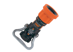
CWIFR currently uses Elkhart Chief 150 g/min (568 l/min) single flow rate nozzles that are designed to operate at a nozzle pressure of 75 psi (517 kPa) as the standard nozzle on 1-3/4 (45 mm) hoselines (similar to the nozzle shown in Figure 1, but CWIFR uses break apart nozzles with a separate tip and shutoff).

Figure 1. Elkhart Chief Nozzle

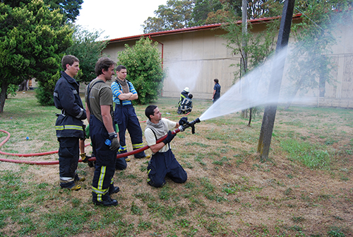
elkhart_chief

Given the same flow rate, a nozzle pressure of 75 psi provides a slight reduction in nozzle reaction in comparison with a nozzle pressure of 100 psi (about 13% when operating a straight stream). However, all things being equal, lower nozzle pressure generally results in larger droplets. Larger droplet size is not necessarily a disadvantage in direct or indirect attack, but can significantly reduce effectiveness of gas cooling. Using the current CWIFR nozzles, flow rate can be increased to approximately 180 gpm by increasing nozzle pressure to 100 psi. However, it is not possible to develop effective streams at flow rates significantly below 150 gpm as a nozzle pressure below 75 psi causes significant deterioration in stream quality, reach, and penetration.

CWIFRs nozzle tests will serve several purposes: First will be to increase members familiarity with the nozzles currently in use, their capabilities, and limitations. The second will be to evaluate other types of nozzles that may provide a broader range of capabilities and increase operational effectiveness.

Three variable flow nozzles and two automatic nozzles will be included in the initial round of testing and evaluation. All of the nozzles selected allow for development of a range of flows at a standard nozzle pressure of 100 psi.

Variable Flow Nozzles

  • Akron Turbojet
    30-60-95-125 g/min (115-230-360-475 l/min)
  • Akron Wide Range Turbojet
    Flow Range 30-95-125-150-200 g/min (115-360-475-550-750 l/min)
  • Elkhart Wide Range Phantom
    Flow Range 30-95-125-150-200 g/min (115-360-475-550-750 l/min)

Automatic Nozzles

  • Ultimatic 10-125 g/min (38-475 l/min)
  • Midmatic 70-200 g/min (265-750 l/min)

Three of these nozzles, the Wide Range Turbojet, Wide Range Phantom, and Midmatic have a higher designed flow capability than the nozzles currently used by CWIFR as well as the capability to develop effective streams at lower flow rates. Two of these nozzles, the Turbojet and Ultimatic have a lower flow capability than the nozzles currently used by CWIFR, but have been found to provide excellent gas cooling capability based on laboratory tests (Handell, 2000) and anecdotal evidence during live fire training and operational firefighting.

Basic Design

The starting point for nozzle evaluation is identification of basic characteristics:

  • Designed Nozzle Pressure
  • Flow Control: Fixed Flow, Variable Flow, Automatic
  • Flow Rates/Range

Physical & Operational Characteristics

Physical and operational characteristics can be as important as stream performance as nozzles must be used under a wide range of operational conditions.

  • Weight
  • Size
  • Size of Bail
  • Flow Control Method
  • Simplicity/Complexity of Operation

Performance Characteristics

Nozzle performance can be evaluated in a variety of different ways ranging from baseline data such as actual flow rates, range of patterns developed, and ease of operation. Other characteristics are a bit more complex such as pattern density and hang time.

  • Actual flow rate vs. specified flow rate
  • Maximum fog pattern angle
  • Reach at designed pressure and flow
  • Ease of Operation within designed pressure and flow range
  • Pattern density during continuous operation
  • Pattern density after pulsed application (2 second delay)
  • Hang time for droplets in pulsed application
  • Performance (as outlined above) outside designed pressure and flow

As identified above, performance will also be evaluated outside the designed pressure and flow range of the nozzles. For example, use of variable flow nozzles at the lowest flow setting at pressures above the designed nozzle pressure can produce extremely small droplets (more on this in a later post).

Finance and Logistical Considerations

While nozzle performance is the most important factor, it is also essential to assess the logistical and financial considerations.

  • Initial purchase price
  • Life-cycle cost
  • Maintenance requirements

Next Steps

The next post in this series will examine the nozzles currently in use by CWIFR and provide additional detail on the evaluation process.

Reference

Handell, A. (2000) Utvrdering av dimstrlrrs effektivitet vid brandgaskylning [Evaluation of the efficiency of fire fighting spray nozzles in a smoke gas cooling situation], Report 5065. Department of Fire Safety Engineering, Lund University, Sweden

Battle Drill Part 3

Sunday, February 21st, 2010

A Quick Review

As discussed in the previous posts in this series, military battle drills are an immediate response to enemy contact that requires fire and maneuver in order to succeed. Battle drills are initiated with minimal commands from the unit leader. Soldiers or marines execute preplanned, sequential actions in response to enemy contact (see Figure 1).

Figure 1. Battle Drill

battle_drill

Battle Drill Part 2 addressed the appropriate reaction of a team of firefighters on a primary hoseline when confronted with rapidly worsening fire conditions that are not readily controllable once they occur (e.g., flashover, wind driven fire conditions). As when a military unit is ambushed, the fire and maneuver of battle drill involves more than one weapon. This post will address the role and reaction of backup lines in the extreme fire behavior battle drill.

Backup Lines

Once a hoseline has been deployed for fire attack it is good practice to stretch a backup line. Klaene and Sanders (2008) observe that backup lines are needed to protect the crew on the initial attack line and to provide additional flow if needed (p. 216). Unfortunately, many firefighters see the backup line as simply another attack line and miss the first and primary function of this hoseline to protect crews on primary hoselines.

The first priority in fire attack operations is to get a hoseline in position to apply water effectively to the fire. To this end, hoselines are deployed in series (attack line first, then backup line) not in parallel, where both lines are attempting to advance and maneuver in the same space. The crew of the backup line can often assist in pulling up additional hose for the attack line (particularly when crews are lightly staffed). As illustrated in Figure 2, the backup line is positioned to protect the means of egress and if necessary support fire attack.

Figure 2. Attack and Backup Line Placement

simple_floor_plan

Extreme Fire Behavior Battle Drill

As discussed in Battle Drill Part 2, the thermal insult experienced in an extreme fire behavior event is dependent on temperature (of gases and compartment linings) and flow of hot gases. The higher the temperature and faster the speed of gas flow, the higher the heat flux. Survival requires that crews on hoselines extinguish or block the flames, cool hot gases, and maneuver out of the flow path to a point of egress or area of safer refuge.

Crews engaged in fire attack or search are often first to encounter rapidly deteriorating fire conditions. Hose Handling and Nozzle Technique Drill 8 outlined the immediate actions that should be taken to support a tactical withdrawal under severe fire conditions. In these circumstances, the crew staffing the backup line has a critical role in supporting withdrawing crews.

Fire conditions that are beyond the capability of a single hoseline may be controlled by the higher flow rate from multiple lines. As noted by Klaene and Sanders (2008) one of the functions of backup lines is to provide additional flow if needed (p. 216). The attack line and backup line operating in a coordinated manner may be able to control fire conditions and allow continuation of fire attack. If this is the case, these lines should be reinforced by deployment of one or more additional backup lines.

If fire conditions cannot be controlled, and the attack line must be withdrawn while maintaining water application to protect the crew, the crew on the backup line can aid in withdrawal of attack and/or search hoselines. If the hoseline is not withdrawn as the firefighter on the nozzle retreats, the hose may kink or become exposed to flames (either of which may result in loss of water supply to the nozzle).

While the attack or search crew is likely to be first to encounter worsening fire conditions, this is not always the case. Depending on fire location and building configuration, fire spread may cut off the attack or search line from behind. In this situation, the backup line becomes the primary means of defense for operating crews.

Regardless of how deteriorating conditions develop, safe and effective tactical withdrawal requires a coordinated effort between interior crews and as soon as possible, report of conditions to Command and if necessary transmit a Mayday message.

Drill 9-Extreme Fire Behavior Battle Drill-The Backup Line: Key hose handling and nozzle techniques when faced with extreme fire behavior are the ability to apply long pulses of water fog or maintaining a continuous flow rate while maneuvering backwards. However, the backup line may initially need to advance to support fire attack, and then if necessary cover and support other crews as they withdraw.

Hose Handling & Nozzle Technique Drill 9 Instructional Plan

Skill in operation and maneuver of a single hoseline is a foundational firefighting skill. However, in the extreme fire behavior battle drill, coordinated operation of the attack and backup line is essential, making Hose Handling & Nozzle Technique Drill 9 an important step in skill development.

References

Klaene, B. & Sanders, R. (2008) Structural Firefighting Strategy and Tactics (2nd ed.). Sudbury, MA: Jones & Bartlett.

2010 Congreso Internacional Fuego y Rescate

Saturday, January 30th, 2010

At a formal dinner on 23 January 2010, Chief Ed Hartin was recognized as an honorary member of Company 1 Germania of the Valdivia, Chile Fire Department. In addition, he was awarded a commendation for supporting the ongoing professional development of the members of Company 1 Germania of the Valdivia, Chile Fire Department and encouraging them in their efforts to share their knowledge with Chiles fire service.

Commendation for Support of Company 1 Germania

commendation

Left to Right: Teniente Juan Esteban Kunstmann, Chief Ed Hartin, Capitn Francisco Silva V.

On 24-27 January 2007, the Company 1 Germania of the Valdivia, Chile Fire Department hosted the first international fire service congress to be held in South America. Participants included over 150 firefighters and officers from Chile, Peru, Argentina, and the United States. The congress provided an opportunity to participate in both classroom and hands-on workshops on a wide range of fire service topics including fire behavior, ventilation, search, rapid intervention, technical rescue, and extrication. While topical areas were diverse, the congress had a substantive emphasis on compartment fire behavior with lectures presented by CFBT-US Chief Instructor Ed Hartin and Geraldo Crespo of Contraincendio in Buenos Aires, Argentina and practical training sessions conducted by Ed Hartin and Juan Esteban Kunstmann of the Valdivia Company 1 Germania.

Lecture Presentation

ed_cl_classroom

Lecture presentations by CFBT-US Chief Instructor Ed Hartin included (click on the links for a copies of the presentations):

CFBT practical skills sessions were held at the Valdivia Fire Departments training center and focused on developing basic skill in nozzle technique and understanding fire development in a compartment.

This is My Nozzle! There are many like it, but this one is mine

ed_cl_practical

Center: Ed Hartin

Practicing Nozzle Techniques

juan_cl_practical

Right: Teniente Juan Esteban Kunstmann

International Collaboration

giancarlo_cl_practical

Left to Right: Battalion Chief Danny Sheridan, FDNY and Capitn Giancarlo Passalacqua Cognoro, Lima, Pe?u Cuerpo General de Bomberos Voluntarios

Congratulations to the members of Company 1 Germania for their success with the first Congreso Internacional Fuego y Rescate! I look forward to working with these outstanding fire service professionals in their ongoing efforts to learn and share knowledge with the fire service throughout Chile, Latin America, and the World.

Ed Hartin, MS, EFO, MIFireE, CFO