Townhouse Fire: Washington, DC
Computer Modeling-Part 2
Monday, October 5th, 2009
This post continues study of an incident in a townhouse style apartment building in Washington, DC with examination of the extreme fire behavior that took the lives of Firefighters Anthony Phillips and Louis Mathews. As discussed in Townhouse Fire: Washington, DC-Computer Modeling Part I, this was one of the first cases where the NIST Fire Dynamics Simulator (FDS) software was used in forensic fire scene reconstruction (Madrzykowski and Vettori, 2000).
Quick Review
As discussed in prior posts, crews working on Floor 1 to locate the fire and secure the door to the stairwell were trapped and burned as a result of rapid progression of a fire in the basement up the open interior stairway after an exterior sliding glass door was opened to provide access to the basement. For detailed examination of incident operations and fire behavior, see:
- Fire Behavior Case Study Townhouse Fire: Washington, DC
- Townhouse Fire: Washington DC-What Happened
- Townhouse Fire: Washington DC-Extreme Fire Behavior
- Townhouse Fire: Washington DC-Computer Modeling
Figure 1. Conditions at Approximately 00:28
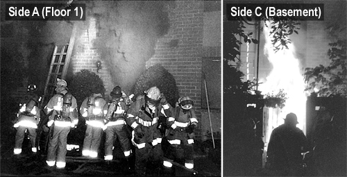
Note: From Report from the Reconstruction Committee: Fire at 3146 Cherry Road NE, Washington DC, May 30, 1999, p. 29 & 32. District of Columbia Fire & EMS, 2000.
Smokeview
Smokeview is a visualization program used to provide a graphical display of a FDS model simulation in the form of an animation or snapshot. Snapshots illustrate conditions in a specific plane or slice within the building. Three vertical slices are important to understanding the fire dynamics involved in the Cherry Road incident: 1) midline of the door on Floor 1, Side A, 2) midline of the Basement Door, Side C, and midline of the Basement Stairwell (see Figure 2). Imagine that the building is cut open along the slice and that you can observe the temperature, oxygen concentration, or velocity of gas movement within that plane.
Figure 2. Perspective View of 3146 Cherry Road and Location of Slices
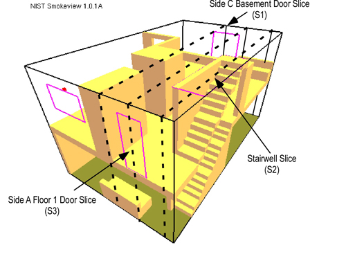
Note: From Simulation of the Dynamics of the Fire at 3146 Cherry Road NE Washington D.C., May 30, 1999, NISTR 6510 (p. 15) by Dan Madrzykowski and Robert Vettori, 2000, Gaithersburg, MD: National Institute for Standards and Technology.
In addition to having an influence on heat release rate, the location and configuration of exhaust and inlet openings determines air track (movement of smoke and air) and the path of fire spread. In this incident, the patio door providing access to the basement at the rear acted as an inlet, providing additional air to the fire. The front door and windows on the first floor opened for ventilation served as exhaust openings and provided a path for fire travel when the conditions in the basement rapidly transitioned to a fully developed fire.
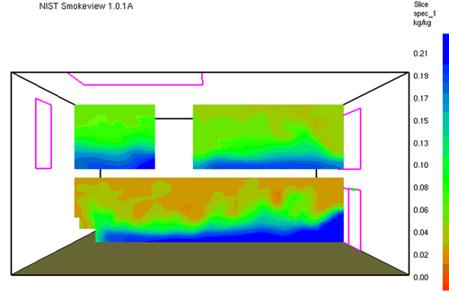
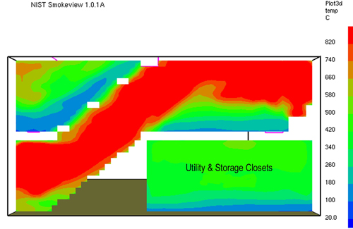
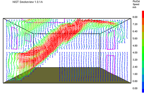
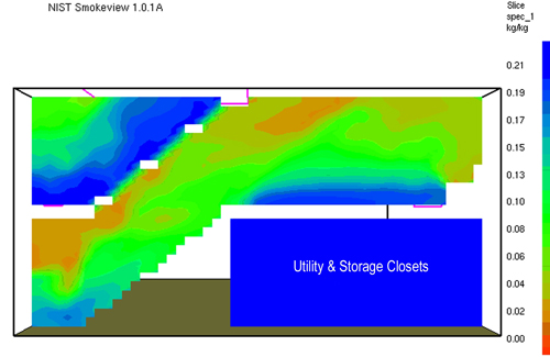
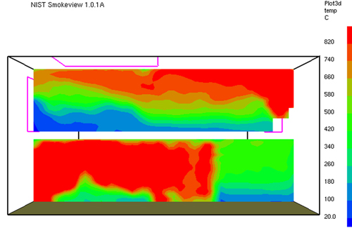
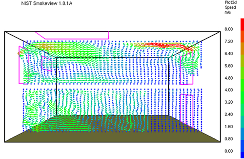
Figures 3-10 illustrate conditions at 200 seconds into the simulation, which relates to approximately 00:27 during the incident, the time at which the fire in the basement transitioned to a fully developed stage and rapidly extended up the basement stairway to Floor 1. Data is presented as a snapshot within a specific slice. Temperature and velocity data are provide for each slice (S1, S2, & S3 as illustrated in Figure 2).
Figure 3. Temperature Along Centerline of Basement Door Side C (S1) at 200 s
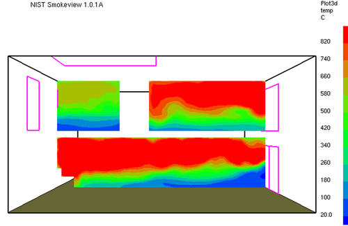
Note: From Simulation of the Dynamics of the Fire at 3146 Cherry Road NE Washington D.C., May 30, 1999, NISTR 6510 (p. 17) by Dan Madrzykowski and Robert Vettori, 2000, Gaithersburg, MD: National Institute for Standards and Technology.
Figure 4. Vector Representation of Velocity Along Centerline of Basement Door Side C (S1) at 200 s
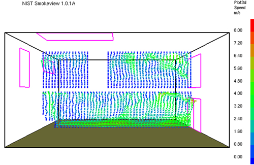
Note: From Simulation of the Dynamics of the Fire at 3146 Cherry Road NE Washington D.C., May 30, 1999, NISTR 6510 (p. 18) by Dan Madrzykowski and Robert Vettori, 2000, Gaithersburg, MD: National Institute for Standards and Technology.
Figure 5. Oxygen Concentration Along Centerline of Basement Door Side C (S1) at 200 s
Note: From Simulation of the Dynamics of the Fire at 3146 Cherry Road NE Washington D.C., May 30, 1999, NISTR 6510 (p. 23) by Dan Madrzykowski and Robert Vettori, 2000, Gaithersburg, MD: National Institute for Standards and Technology.
Figure 6. Temperature Slice Along Centerline of Basement Stairwell (S2) at 200 s
Note: From Simulation of the Dynamics of the Fire at 3146 Cherry Road NE Washington D.C., May 30, 1999, NISTR 6510 (p. 21) by Dan Madrzykowski and Robert Vettori, 2000, Gaithersburg, MD: National Institute for Standards and Technology.
Figure 7. Vector Representation of Velocity Along Centerline of Basement Stairwell (S2) at 200 s
Note: From Simulation of the Dynamics of the Fire at 3146 Cherry Road NE Washington D.C., May 30, 1999, NISTR 6510 (p. 22) by Dan Madrzykowski and Robert Vettori, 2000, Gaithersburg, MD: National Institute for Standards and Technology.
Figure 8. Oxygen Concentration Along Centerline of Basement Stairwell (S2) at 200 s
Note: From Simulation of the Dynamics of the Fire at 3146 Cherry Road NE Washington D.C., May 30, 1999, NISTR 6510 (p. 24) by Dan Madrzykowski and Robert Vettori, 2000, Gaithersburg, MD: National Institute for Standards and Technology.
Figure 9. Temperature Slice Along Centerline of Floor 1 Door Side A (S3) at 200 s
Note: From Simulation of the Dynamics of the Fire at 3146 Cherry Road NE Washington D.C., May 30, 1999, NISTR 6510 (p. 19) by Dan Madrzykowski and Robert Vettori, 2000, Gaithersburg, MD: National Institute for Standards and Technology.
Figure 10. Vector Representation of Velocity Along Centerline of Floor 1 Door Side A (S3) at 200 s
Note: From Simulation of the Dynamics of the Fire at 3146 Cherry Road NE Washington D.C., May 30, 1999, NISTR 6510 (p. 20) by Dan Madrzykowski and Robert Vettori, 2000, Gaithersburg, MD: National Institute for Standards and Technology.
Figure 11. Perspective Cutaway, Flow/Temperature, Velocity, and O2 Concentration
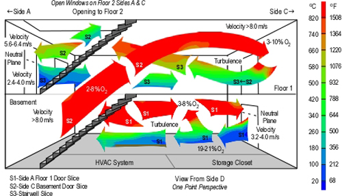
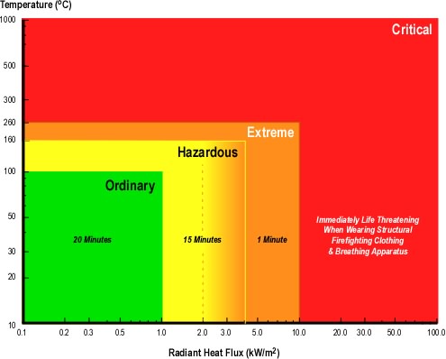
Figure 12. Thermal Exposure Limits in the Firefighting Environment
Note: Adapted from Measurements of the firefighting environment. Central Fire Brigades Advisory Council Research Report 61/1994 by J.A. Foster & G.V. Roberts, 1995. London: Department for Communities and Local Government and Thermal Environment for Electronic Equipment Used by First Responders by M.K. Donnelly, W.D. Davis, J.R. Lawson, & M.J. Selepak, 2006, Gaithersburg, MD: National Institute of Standards and Technology.
Compartment Fire Thermal Hazards
The temperature of the atmosphere (i.e., smoke and air) is a significant concern in the fire environment, and firefighters often wonder or speculate about how hot it was in a particular fire situation. However, gas temperature in the fire environment is a bit more complex than it might appear on the surface and is only part of the thermal hazard presented by compartment fire.
Tissue temperature and depth of penetration determine the severity of a thermal burn. Temperature and penetration are dependent on the amount of energy absorbed and the duration of the thermal insult as well as the properties of human tissue. In a compartment fire, firefighters absorb energy from any substance that has a temperature above 37o C (98.6o F), including hot compartment linings, contents, the hot gas layer, and flames. The dominant mechanisms of heat transfer involved in this process are convection and radiation (although conduction through personal protective equipment is also a factor to be considered).
The total thermal energy received is described in joules per unit area. However, the speed or rate of energy is transferred may be more important when assessing thermal hazard. Heat (thermal) flux is used to define the rate of heat transfer and is expressed in kW/m2 (Btu/hr/ft2).
One way to understand the interrelated influence of radiant and convective heat transfer is to consider the following scenario. Imagine that you are standing outside in the shade on a hot, sunny day when the temperature is 38o C (100o F). As the ambient temperature is higher than that of your body, energy will be transferred to you from the air. If you move out of the shade, your body will receive additional energy as a result of radiant heat transfer from the sun.
Convective heat transfer is influenced by gas temperature and velocity. When hot gases are not moving or the flow of gases across a surface (such as your body or personal protective equipment) is slow, energy is transferred from the gases to the surface (lowering the temperature of the gases, while raising surface temperature). These lower temperature gases act as an insulating layer, slowing heat transfer from higher temperature gases further away from the surface. When velocity increases, cooler gases (which have already transferred energy to the surface) move away and are replaced by higher temperature gases. When velocity increases sufficiently to result in turbulent flow, hot gases remain in contact with the surface on a relatively constant basis, increasing convective heat flux.
Radiant heat transfer is influenced by proximity and temperature of the radiating body. Radiation increases by a factor of four when distance to the hot material is reduced by half. In addition, radiation increases exponentially (as a function of the fourth power) as absolute temperature increases.
Thermal hazard may be classified based on hot gas temperature and radiant heat flux (Foster & Roberts, 1995; Donnelly, Davis, Lawson, & Selpak, 2006) with temperatures above 260o C (500o F) and/or radiant heat flux of 10 kW/m2 (3172 Btu/hr/ft2) being immediately life threatening to a firefighter wearing a structural firefighting ensemble (including breathing apparatus). National Institute of Standards and Technology (NIST) experiments in a single compartment show post flashover gas temperatures in excess of 1000o C (1832o F) and heat flux at the floor may exceed 170 kW/m2 (Donnelly, Davis, Lawson, & Selpak, 2006). Post flashover conditions in larger buildings with more substantial fuel load may be more severe!
Figure 11 integrates temperature, velocity, and oxygen concentration data from the simulation (Figures 3-10). Detail and accuracy is sacrificed to some extent in order to provide a (somewhat) simpler view of conditions at 200 seconds into the simulation (approximately 00:27 incident time). Note that as in individual slices, data is presented as a range due to uncertainty in the computer model.
Alternative Model
In addition to modeling fire dynamics based on incident conditions and tactical operations as they occurred, NIST also modeled the incident with a slightly different ventilation profile.
The basic input for the alternate simulation was the same as the simulation of actual incident conditions. Ventilation openings and timing was the same, with one exception; the sliding glass door on Floor 1, Side C was opened at 120 s into the simulation. Conditions in the basement during the alternative simulation were similar to the first. However, on Floor 1, the increase in ventilation provided by the sliding glass door on Side C resulted in a shallower hot gas layer and cooler conditions at floor level. A side-by-side comparison of the temperature gradients in these two simulations is provided in Figure 13.
Figure 13. Comparison of Temperature Gradients Along Centerline of Basement Stairwell (S2) at 200 s

Note: Adapted from Simulation of the Dynamics of the Fire at 3146 Cherry Road NE Washington D.C., May 30, 1999, NISTR 6510 (p. 21 & 27) by Dan Madrzykowski and Robert Vettori, 2000, Gaithersburg, MD: National Institute for Standards and Technology.
The NIST Report (Madrzykowski & Vettori, 2000) identified that the significant difference between these two simulations is in the region close to the floor. In the alternative simulation (Floor 1, Side C Sliding Glass Door Open) between the doorway to the basement and the sofa, the temperatures from approximately 0.6 m (2 ft) above the floor, to floor level are in the range of 20 °C to 100 °C (68°F to 212 °F), providing at least an 80 °C (176 °F) temperature reduction.
While this is a considerable reduction in gas temperature, it is essential to also consider radiant heat flux from the hot gas layer. Given the temperature of the hot gases from the ceiling level to a depth of approximately 3′ (0.9 m), the heat flux at the floor would likely have been in the range of 15-20 kW/m2 (or greater).
Questions
- Temperatures vary widely at a given elevation above the floor. Consider the slices illustrated in Figures 3, 6, and 9, and identify factors that may have influenced these major differences in temperature.
- How might the variations in temperature illustrated in Figures 3, 6, and9 and location of Firefighters Phillips (basement doorway), Mathews (living room, C/D corner), and Morgan (between Phillips & Mathews) have influenced their injuries?
- Examine the velocity of gas movement illustrated in Figures 4, 7, and 10 and integrated illustration conditions in Figure 11. How does this correlate to the photos in Figure 1 illustrating incident conditions at approximately 00:28?
- Explain how the size and configuration of ventilation openings resulted in a bi-directional air track at the basement door on Side C.
- How did the velocity of hot gases in the stairwell and living room influence the thermal insult to Firefighters Phillips, Mathews, and Morgan? What factors caused the high velocity flow of gases from the basement stairwell doorway into the living room?
- Rescue 1B noted that the floor in the living room was soft while conducting primary search at approximately 00:30. Why didn’t the parallel chord trusses in the basement fail sooner? Is there a potential relationship between fire behavior and performance of the engineered floor support system in this incident?
- How might stability of the engineered floor support system have differed if the sliding glass door in the basement had failed prior to the fire departments arrival? Why?
- How might the double pane glazing on the windows and sliding glass doors have influenced fire development in the basement? How might fire development differed if these building openings had been fitted with single pane glazing?
- What was the likely influence of turbulence in the flow of hot gases and cooler air on combustion in the basement? What factors influenced this turbulence (examine Figures 4, 7, and 10) illustrating velocity of flow and floor plan illustrated in conjunction with the second question)?
- How did conditions in the area in which Firefighters Phillips, Mathews, and Morgan were located correlate to the thermal exposure limits defined in Figure 12? How did this change in the alternate scenario? Remember to consider both temperature and heat flux.
Extended Learning Activity
The Cherry Road case study provides an excellent opportunity to develop an understanding of the influence of building factors, burning regime, ventilation, and tactical operations on fire behavior. These lessons can be extended by comparing and contrasting this case with other cases such as the 1999 residential fire in Keokuk, Iowa that took the lives Assistant Chief Dave McNally, Firefighter Jason Bitting, and Firefighter Nathan Tuck along with three young children. For information on this incident see NIOSH Death in the Line of Duty Report F2000-4, NIST report Simulation of the Dynamics of a Fire in a Two Story Duplex, NIST IR 6923.and video animation of Smokeview output from modeling of this incident

Ed Hartin, MS, EFO, MIFireE, CFO
References
District of Columbia (DC) Fire & EMS. (2000). Report from the reconstruction committee: Fire at 3146 Cherry Road NE, Washington DC, May 30, 1999. Washington, DC: Author.
Madrzykowski, D. & Vettori, R. (2000). Simulation of the Dynamics of the Fire at 3146 Cherry Road NE Washington D.C., May 30, 1999, NISTR 6510. August 31, 2009 from http://fire.nist.gov/CDPUBS/NISTIR_6510/6510c.pdf
National Institute for Occupational Safety and Health (NIOSH). (1999). Death in the line of duty, Report 99-21. Retrieved August 31, 2009 from http://www.cdc.gov/niosh/fire/reports/face9921.html


