Posts Tagged ‘burning regime’

Contra Costa County LODD

Thursday, May 7th, 2009

As discussed in previous posts, developing mastery of the craft of firefighting requires experience. However, it is unlikely that we will develop the base of knowledge required simply by responding to incidents. Case studies provide an effective means to build our knowledge base using incidents experienced by others.

Introduction

The deaths of Captain Matthew Burton and Engineer Scott Desmond in a residential fire were the result of a complex web of circumstances, actions, and events. This case study was developed using the Contra Costa County Fire Protection District Investigative Report and NIOSH Death in the Line of Duty Report 2007-28 and video taken by a Firefighter assigned to Quint 76 (Q76), the first alarm truck company. This case study focuses on the fire behavior and related tactical operations involved in this incident. However, there are a number of other lessons that may be learned from this incident and readers are encouraged to review both the fire district’s investigation and NIOSH report for additional information.

The Case

Early on the morning of July 21, 2007, Captain Matthew Burton and Engineer Scott Desmond were performing primary search of a single family dwelling in San Pablo, California. During their search, they were trapped by rapidly deteriorating conditions and died as a result of thermal injuries and smoke inhalation. Two civilian occupants also perished in the fire.

Figure 1. 149 Michele Drive-Alpha/Delta Corner
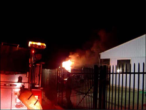
figure_1_fgi

Note: Contra Costa Fire Protection District (Firefighter Q76) Photo, Investigation Report: Michele Drive Line of Duty Deaths. This photo illustrates conditions shortly after 0159 (Q76 time of arrival).

Building Information

The fire occurred in a 1,224 ft2 (113.7 M2), one-story, wood frame dwelling with an attached garage at 149 Michele Drive in San Pablo (Contra Costa County), California. The house was originally built in 1953 and remodeled in 1991 with the addition of a pitched rain roof over the original (flat) roof.

This single story structure was of Type V, platform frame construction. The building was originally constructed with 4″ x 8″ (102 mm x 203 mm) beams supporting a flat roof with 2″ x 6″ (51 mm x 152 mm) tongue and groove planking with a built-up overlay consisting of several layers of tar and gravel. The pitched roof was constructed of 2″ x 8″ (51 mm x 203 mm) rafters covered with plywood and asphalt composite shingles. The ridge of the pitched roof was parallel to Side A. The gable ends on Sides B and D were constructed of plywood and fitted with a small gable vent.

Figure 2. Floor Plan-149 Michelle Drive
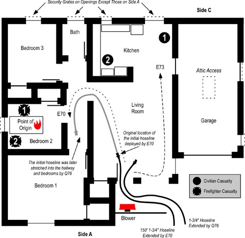
figure_2_michele_dr_floor_plan

Note: This floor plan is based on data provided in the Contra Costa Fire Protection District Investigation Report and is not drawn to scale. The position of exterior doors and condition of windows as illustrated is based on the narrative or photographic evidence. Interior doors are shown as open as illustrated in the report. Fire service casualties are designated as follows: 1) Captain Burton, 2) Engineer Desmond.

All windows with the exception of the Living Room and Bedroom 1 (see Figure 2) were fitted with security bars (see Figure 3). The front door was the primary exit. In addition, an additional exit was provided from the kitchen through the garage to the exterior on Side D. The exterior door on Side D was fitted with a security grate.

Figure 3. View of Side C from the B/C Corner
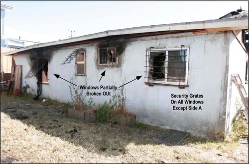
figure_3_side_c_window_framed

Figure 4. Hallway and Bedroom 2

figure_5_living_room_framed

Note: Figures 3 & 4 adapted from Contra Costa Fire Protection District Photos (brightness and contrast adjusted to provide increased clarity).

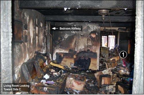
Interior walls were gypsum board with wood veneer paneling on some of the walls (e.g., living room). All ceilings with the exception of the kitchen were exposed 2″ x 6″ (51 mm x 152 mm) tongue and groove planking (see Figure 4). The kitchen ceiling was covered with gypsum board. Ceiling height was 8′ (2.4 M).

Figure 5. Living Room
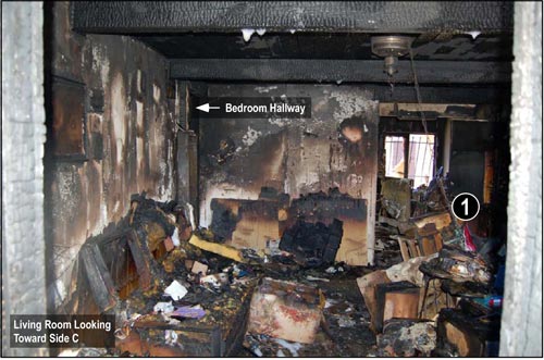
figure_5_living_room_framed1

Note: Adapted from Contra Costa Fire Protection District Photos, Investigation Report: Michele Drive Line of Duty Deaths.

The Fire

Investigators determined that the fire likely originated on or near the east end of the bed in Bedroom 2 (see Figures 2 & 3). The likely source of ignition was improper discard of smoking materials. Developing into growth stage, the fire progressed from Bedroom 2 into the hallway (see Figures 2 & 4) leading to the living room, dining area, and kitchen (see Figures 2 & 5). It is likely that the door on Side A was closed at the time of ignition, but was opened by an occupant exiting some time after discovery of the fire.

Dispatch Information

Occupants discovered the fire and notified a private alarm company via two-way intercom at 0134. The alarm company notified the Contra Costa Regional Fire Communications Center of receipt of a fire alarm from 149 Michelle Drive at 0136 using the non-emergency telephone number. The alarm company did not indicate that they had talked to the resident who had reported a fire, but simply that they had received a fire alarm. The caller was placed on hold due to a higher priority 911 call. The dispatcher returned to the call from the alarm company at 0142 to obtain the address and callback information. Two attempts were made to call the incident location prior to dispatch of Engine 70 at 0144 to investigate the alarm. Contra Costa County Fire Protection District (CCCFPD) Engine 70 responded at 0145.

Shortly after Engine 70 responded, the communications center received a cell phone call from the female occupant at 149 Michelle Drive. This call was originally received by the California Highway Patrol and transferred to Contra Costa County Regional Fire Communications Center. The caller reported a residential fire and indicated that she had not been able to get her husband out of the building. Between the time that she spoke to the dispatcher and arrival of Engine 70, the female occupant reentered the building to attempt to rescue her husband (leaving the door on Side A open).

At 0146, the dispatcher upgraded the response to a residential fire and added two additional engines, a quint (as the truck company), and a battalion chief. Subsequent to the upgrade to a residential fire, additional 911 calls were received reporting a residential fire at 149 Michelle Drive.

Resources dispatched on the first alarm were as follows: Engine 70 (already responding on the initial dispatch for a residential alarm), Engine 69 (CCCFPD) as well as Rodeo-Hercules Fire Protection District Quint 76, and Battalion 7.  Richmond Fire Department Engine 68 was requested for automatic aid response through the Richmond Communications Center to fill out the first alarm assignment. Pinole Fire Department Engine 73 cleared a medical call a short distance away from the incident location and added themselves to the first alarm assignment. With the addition of Engine 73, the dispatcher canceled response of Engine 68 through Richmond Dispatch.

Note: Engine 73 was using an apparatus normally assigned at Station 74 which was marked with the designation Engine 74. This created some confusion during initial incident operations.

Weather Conditions

Conditions were clear, temperature was approximately 61o F (16o C), with a south to southeast (Side D to Side B) wind at between 2 and 6 mph (3.2 and 9.7 kph).

Conditions on Arrival

Shortly prior to arrival, Engine 70 reported “smoke showing a block outand was advised by the dispatcher that the female occupant had been trying to get her husband out of the house and that it was uncertain if she had been successful. Engine 70 arrived at 0150, reported heavy smoke and fire from a single-story residential structure (flames and smoke were exiting from the open front door and large living room window on Side A), and established Command. Due to delays in the dispatch process, the time from the initial auomatic alarm until the arrival of E70 was approximately 16 minutes.(Refer to Contra Costa Fire Protection District, Investigation Report: Michele Drive Line of Duty Deaths for additional information regarding factors influencing the dispatch delay.

Questions

The following questions provide a basis for examining the first segment of this case study. You have an advantage that Captain Burton did not in that you are provided with a floor plan, photographs of Side C and the interior, and have knowledge of the eventual outcome. However, it is important that you place yourself in the situation encountered on arrival.

  1. What stage(s) of fire and burning regime(s) were present in the building when E70 arrived? Consider potential differences in conditions in the living room, hallway, and bedrooms?
  2. If you suspect that fire conditions in the living room were different than the hallway and bedrooms, why might this be the case? What evidence supports your position? What are your assumptions?
  3. While limited information is available about the fire behavior indicators present during this incident, what Building, Smoke, Air Track, Heat, and Flame (B-SAHF) indictors did E70 observe when they arrived?
  4. What B-SAHF indicators would you anticipate could have been observed on Sides B and C had this reconnaissance been conducted prior to making entry?
  5. If you were faced with this situation, fire showing from the front door and window of a single family dwelling with persons reported, what actions would you take?
  6. How do you think your selection of tactics would have influenced fire behavior and interior conditions?

Tactical Operations & Fire Behavior

My next post will examine tactical operations conducted by the first arriving companies and fire behavior encountered inside the building.

Deliberate Practice

Ed Hartin, MS, EFO, MIFireE, CFO

References

Contra Costa County Fire Protection District.  (2008). Investigation Report: Michele Drive Line of Duty Deaths. Retrieved February 13, 2009 from http://www.cccfpd.org/press/documents/MICHELE%20LODD%20REPORT%207.17.08.pdf

National Institute for Occupational Safety and Health (2009).  Death in the Line of Duty Report 2007-28. Retrieved May 5, 2009 from http://www.cdc.gov/niosh/fire/pdfs/face200728.pdf.

Extreme Fire Behavior:
An Organizational Scheme (Ontology)

Thursday, April 2nd, 2009

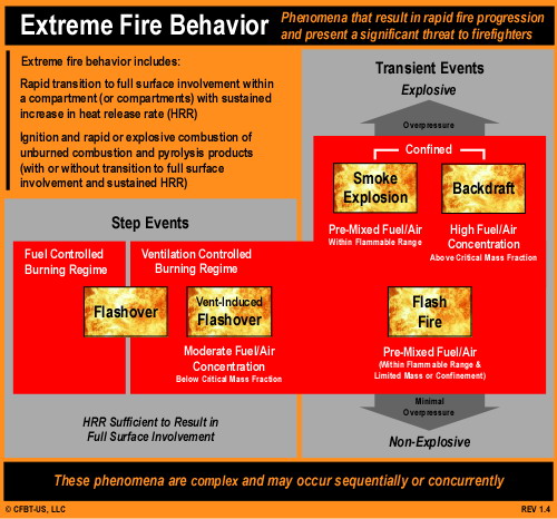
In Fire Gas Ignitions and Language & Understanding: Extreme Fire Behavior, I pointed out the ambiguity in definition of terms related to extreme fire behavior. In the structural firefighting context, the term extreme fire behavior is used to identify phenomena that result in rapid fire progression and present a significant threat to firefighters. Rapid fire progression may involve transition to a fully developed fire (e.g., flashover) or it may involve a brief, but significant increase in energy release (e.g., backdraft, flash fire, smoke explosion).

One way to begin the process of reducing the ambiguity surrounding extreme fire behavior phenomena is to establish a framework for organizing and classifying extreme fire behavior phenomena.

Organizing Concepts

The organization and classification framework presented in this post is based on the following general concepts:

  • Extreme fire behavior involves a rapid increase in heat release rate (HRR).
  • The increase in HRR can be sustained or it may be relatively brief.
  • Brief increases in HRR may or may not result in overpressure inside a compartment or building.
  • Extreme fire behavior may occur in a fuel or ventilation controlled burning regime
  • Concentration (mass fraction) of fuel in the gas phase influences the nature of extreme fire behavior.
  • Depending on existing or developing conditions, extreme fire behavior may be initiated by reaching critical HRR, an increase in ventilation, or a source of ignition.

It is likely that there are additional concepts or criteria that may prove useful in the process of organizing and classifying extreme fire behavior. However, these concepts provide a starting point for this process and discussion.

Classification by Outcome

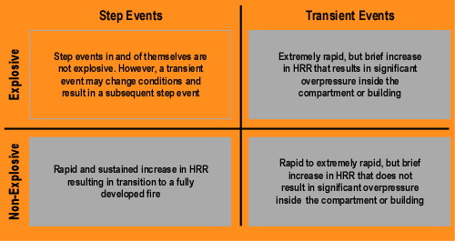
At the highest level, extreme fire behavior phenomena are classified on the basis of the duration of increased HRR. If increased HRR is sustained and the fire enters a (relatively) steady state of combustion, the phenomena would be classified as a Step Event. However, if the increase in HRR is brief and not sustained, the phenomena would be classified as a Transient Event.

A rapid increase in HRR results in increased temperature of the atmosphere inside the compartment. As temperature increases, the gas (i.e., air and smoke) volume within the compartment will expand. If the gas volume inside the compartment is confined and cannot expand, pressure will increase, in some cases significantly! Transient events are classified as Explosive (resulting in a significant overpressure) or Non-Explosive (not resulting in a significant overpressure). Explosiveness is in part a result of the mixture of gas phase fuel and air present in the compartment and the extent to which combustion is confined.

Classification of extreme fire behavior phenomena on the basis of outcome are illustrated graphically in Figure 1.

Figure 1. Outcome Classification

outcome_classification_sr

Classification by Conditions

Additional clarity can be obtained by examining extreme fire behavior phenomena on the basis of requisite conditions for occurrence. However, it is important to keep in mind that conditions are rarely uniform in structure fires. Different compartments (e.g., habitable spaces, voids) can have dramatically different conditions in burning regime, fuel concentration, oxygen concentration, and temperature.

In a compartment with sufficient openings, flashover can occur prior to fire growth becoming significantly limited by available ventilation. However, a majority of extreme fire behavior phenomena occur when the fire is in a ventilation controlled burning regime. As compartment fire development becomes limited by ventilation, not all of the gas phase fuel resulting from pyrolysis is burned. This excess pyrolizate increases both the mass and concentration of fuel within the compartment (and other compartments as smoke spreads through the building). Concurrently, with increased fuel concentration, oxygen concentration decreases.

Provided a source of ignition with sufficient energy, gas phase fuel/air mixtures within the flammable range can be ignited. However, if the fuel/air mixture is too rich, additional air must be introduced and mixed with the fuel in order for combustion to occur.

For extreme fire behavior phenomena occurring within a ventilation controlled burning regime, the following factors can be used to further define the nature of the phenomena:

  • Fuel Concentration
  • Oxygen Concentration
  • Extent of Confinement

The combination of fuel/air mixture and extent of confinement define what type of initiating event (contact with source of ignition, increase in ventilation, or both) will be necessary for the extreme fire behavior to occur.

Graphical Representation

It is often easier to see how things are organized using a visual model or diagram. However, it is not so simple to capture a high level of complexity in a simple drawing. Figure 2 illustrates the concepts presented in this post regarding classification of extreme fire behavior phenomena.

extreme_fire_behavior_sr

This is a work in progress and feedback is greatly appreciated!

Ed Hartin, MS, EFO, MIFireE, CFO

Wind Driven Fires: Tactical Problem

Monday, March 16th, 2009

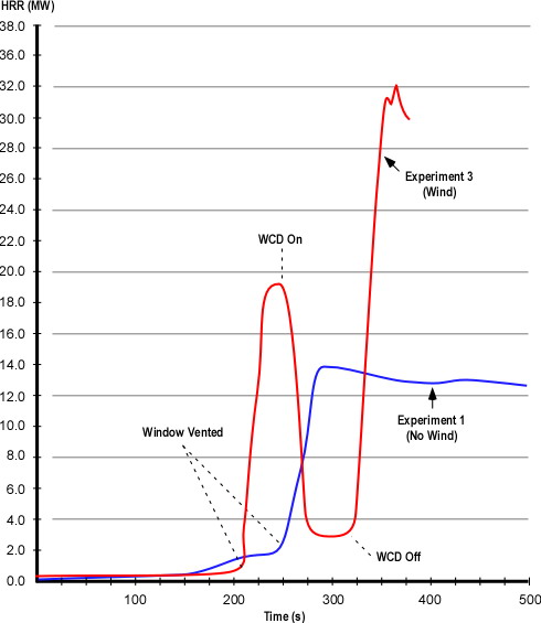
My last post examined National Institute for Standards and Technology (NIST) tests of wind control devices to mitigate hazards presented during wind driven compartment fires (Fire Fighting Tactics Under Wind Driven Conditions). Heat release rate (HRR)  data from Experiment 1 (baseline test with no wind) and Experiment 3 (wind driven) illustrates the dramatic influence of increasing ventilation to a ventilation controlled fire and even more dramatic impact when increased ventilation is coupled with wind (see Figure 1). This post posed several questions related to the HRR data from these experiments.

Figure 1. Heat Release Rates in Experiments 1 (Baseline) and 3 (Wind Driven)

hrr_experiment3Note: Adapted from Firefighting Tactics Under Wind Driven Conditions.
Questions

Examine the HRR curves in Figure 1 and answer the following questions:

  • What effect did deployment of the wind control device have on HRR and why did this change occur so quickly?
  • How did HRR change when the wind control device was removed and why was this change different from when the window was vented?
  • What factors might influence the extent to which HRR changes when ventilation is increased to a compartment fire in a ventilation controlled burning regime?

Answers: Application of the wind control device rapidly decreased heat release rate from approximately 19 MW to 5 MW. With the window covered, the fire lacked sufficient oxygen to maintain the higher rate of HRR. As oxygen was quickly consumed (and oxygen concentration was decreased) by the large volume of flaming combustion in the compartments, heat release rate was rapidly reduced.

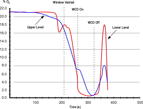
As with the change in HRR when the window was vented, removal of the wind control device resulted in an extremely rapid increase in HRR as additional oxygen was provided to the ventilation controlled fire inside the structure. In this case, the increase was even more significant with the peak HRR reaching approximately 32 MW. Examination of the oxygen concentration curve provides a hint of why this might have been the case (see Figure 2). The oxygen concentration was higher before the window was vented than when the wind control device was removed. The more rapid and greater rise in HRR is likely a result of the extent to which the fire was ventilation controlled and the available concentration of gas phase fuel. After the wind control device was removed, note that the oxygen concentration increased sharply (which relates to the rapid increase in HRR), followed by a rapid decrease as ventilation was inadequate to maintain that rate of combustion.

Figure 2. Oxygen Concentration in the Bedroom

o2_bedroom_test31

Note: Adapted from Firefighting Tactics Under Wind Driven Conditions.
Practical Application

The results of the NIST research are extremely interesting to students of fire behavior. However, it is essential that we be able to transform this information into knowledge that has practical application. This gives rise to three fundamental questions:

  • How do changes in ventilation influence fire behavior? Note that this is always a concern, not just under wind conditions!
  • What impact will wind have if the ventilation profile changes?
  • What tactical options will be effective in mitigating hazards presented by extreme fire behavior under wind driven conditions?

It is important to consider air track and the flow path from inlet to exhaust opening and the potential consequences of introducing air under pressure without (or with an inadequate) exhaust opening. Both can have severe consequences!

Tactical Problem

One good way to wrestle with the influence of wind on compartment fire behavior is to put it into a realistic context. In the following tactical problem you will be presented with an incident scenario and a series of questions. Apply what you have learned and consider how you would approach this incident.

Resources: You have what you have! Use your normal apparatus assignment and staffing levels when working through this tactical problem.

Weather Information: Conditions are clear with a temperature of 20o C (68o F) and a 24 kph (15 mph) wind out of the Northwest.

Dispatch Information: You have been dispatched to a residential fire at 0700 on a Sunday morning. The caller reported seeing smoke from a house at 1237 Lakeview Drive. After companies go enroute, the dispatcher provides an update that she is receiving multiple calls for a fire at this location.

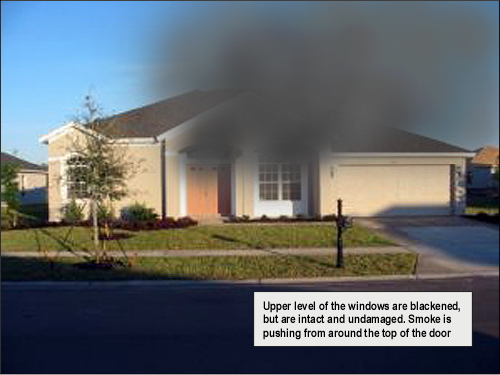
Conditions on Arrival: Approaching the incident location you observe a moderate volume of medium gray smoke from a wood frame, single family dwelling (most structures in this area are of lightweight construction). Smoke is blowing towards the A/D corner of the structure. As illustrated in Figure 3, smoke is visible from the front entry (window and door) of the house and it appears that smoke is showing from Side C as well. On closer examination, you observe that the upper level of the windows on Side A are stained with condensed pyrolysis products, but are intact.

Figure 3. View from Side A

wind_a

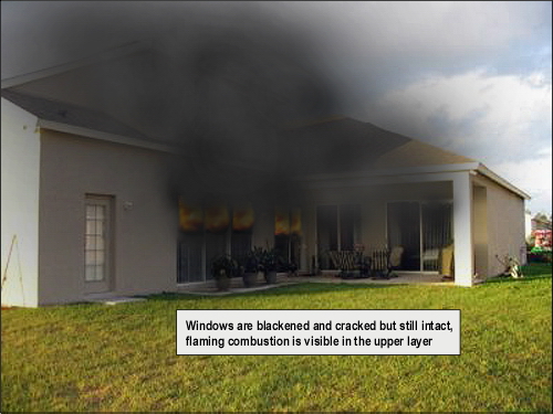
360o Reconnaissance: Moving down Side B, you observe a substantial body of fire in the center of the house. Smoke is pushing from around several sliding glass doors on Side B (see Figure 4) and flames are visible in the upper layer. The glass in the sliding doors is blackened and cracked, but is still intact. Smoke is also visible from around a large window on Side B Floor 2. Smoke discharge on Side B is swirling and being pushed up over the roof by the wind.

Figure 4. View from the BC Corner

wind_bc

Proceeding around the structure to Sides C and D, you observe a small amount of smoke pushing out from around the windows on Side D.

Questions: The first set of questions deals with size-up and development of an initial plan of action.

  • What B-SAHF indicators do you observe in Figures 2 and 3?
  • What stage(s) of fire development is (are) likely to exist in the structure?
  • What burning regime is the fire in?
  • How is the fire likely to develop in the time that it will take to develop and implement your incident action plan?
  • Would you have given orders to your crew (or would they have taken pre-planned standard actions) based on your observation of conditions on Side A (Figure 1)? If so what would have been done? Why?
  • Would your action plan have changed based on your observations from the B/C corner? What would you do differently? Why?
  • What is your action plan at this point? Do you have sufficient resources? What orders would you give the first alarm companies? What actions would you have your crew take? Why?

Your action plan is dependent on size-up and assessment of incident conditions.  Variation in conditions may result in a change in the priority or sequence of tactical action. Would your action plan have been different if the dispatcher had indicated that the caller was trapped in the house? If it would have, what would you have done differently? Why?

Things to Think About

This tactical problem presents a number of challenges. Click on the link to examine the Floor Plan and then consider the following questions:

  • What conditions would firefighters have encountered if they made entry through the door on Side A (front door)? Why?
  • How would these conditions have changed if glass in one or more of the sliding doors on Side B had failed after firefighters had made entry? Why?
  • What conditions would have resulted if the glass in one or more of the sliding doors on Side B had failed and the door on Side A was not open? Why?
  • What options for fire attack and tactical ventilation would have been effective in this situation? Would your choice fire attack and tactical ventilation location, sequence, and coordination have varied based on the report of occupants? Why?
  • How did your knowledge of the results of the NIST tests on wind driven fires impact your understanding of this incident? How did this understanding influence your tactical decision-making?

It is important to practice strategic and tactical decision-making. However, it is also important to think about how and why we make these decisions. This meta-learning (learning about our learning) has a significant impact on our professional development and ability to learn our craft.

Remember the Past

As discussed in previous posts, it is important to honor the sacrifices of firefighters who have died in the line of duty and not lose lessons learned as time passes. The following narratives were taken from the United States Fire Administration (USFA) reports on Firefighter Line of Duty Deaths (1994 and 2004).

March 29, 1994
Captain John Drennan, 49, Career
Firefighter James Young, 31, Career
Firefighter Christopher Seidenburg, 25, Career
Fire Department of the City of New York, New York

On March 29, three firefighters trapped in the stairwell of a brownstone were burned when they were enveloped in fire while attempting to force their way through a heavy steel door to a second floor apartment. Captain John Drennan, Firefighter James Young, and Firefighter Christopher Seidenburg of the New York City Fire Department were conducting a search when the hot air and toxic gases that collected in the stairwell erupted into flames as other fire crews forced entry into the first floor apartment where the fire had originated. The fire exhibited characteristics of both a backdraft and a flashover. Firefighter Young, in the bottom position on the stairs, was burned and died at the scene. Firefighter Seidenberg and Captain Drennan were rescued by other firefighters. They were transported to a burn unit with third and fourth degree burns over 50 of their bodies. Seidenburg died the next day. Drennan passed away several weeks later. The fire cause was determined to be a plastic bag left by the residents on top of the stove of the floor apartment.

For additional information on this incident see:

Bukowski, R. (1996). Modeling a backdraft: The 62 Watts Street incident. Retrieved March 14, 2009 from http://fire.nist.gov/bfrlpubs/fire96/PDF/f96024.pdf

March 21, 2003 – 0850
Firefighter Oscar “Ozzie” Armstrong, III, Age 25, Career
Cincinnati Fire Department, Ohio

Firefighter Armstrong and the members of his fire company responded to the report of a fire in a two-story residence. The first fire department unit on the scene, a command officer, reported a working fire.

Firefighter Armstrong assisted with the deployment of a 350-foot, 1-3/4-inch handline to the front door of the residence. Once the door was forced open, firefighters advanced to the interior. The handline was dry as firefighters advanced; the hose had become tangled in a bush.

As the line was straightened and water began to flow to the nozzle, a flashover occurred. The firefighters on the handline left the building and were assisted by other firefighters on the front porch of the residence. All firefighters were ordered from the building, air horns were sounded to signal a move from offensive to defensive operations.

Several firefighters saw Firefighter Armstrong trapped in the interior by rapid fire progress. These firefighters advanced handlines to the interior and removed Firefighter Armstrong. A rapid intervention team assisted with the rescue.

Firefighter Armstrong was severely burned. He was transported by fire department ambulance to the hos­pital where he later died.

The origin of the fire was determined to be a pan of oil on the stove.

For additional information on this incident see:

National Institute for Occupational Safety and Health (NIOSH). (2005). Death in the line of duty report F2003-12. Retrieved March 14, 2009 from http://www.cdc.gov/niosh/fire/pdfs/face200312.pdf

Laidlaw Investigation Committee. (2004)Line of duty death enhanced report Oscar Armstrong III March 21, 2004. Retrieved March 14, 2009  from http://www.iafflocal48.org/pdfs/enhancedloddfinal.pdf

Ed Hartin, MS, EFO, MIFireE, CFO

References

Madrzykowski, D. & Kerber, S. (2009). Fire fighting tactics under wind driven conditions. Retrieved (in four parts) February 28, 2009 from http://www.nfpa.org/assets/files//PDF/Research/Wind_Driven_Report_Part1.pdf; http://www.nfpa.org/assets/files//PDF/Research/Wind_Driven_Report_Part2.pdf;http://www.nfpa.org/assets/files//PDF/Research/Wind_Driven_Report_Part3.pdf;http://www.nfpa.org/assets/files//PDF/Research/Wind_Driven_Report_Part4.pdf.

United States Fire Administration (USFA). (1995) Analysis report on firefighter fatalities in the United States in 1994. Retrieved March 14, 2009 from http://www.usfa.dhs.gov/downloads/pdf/publications/ff_fat94.pdf

United States Fire Administration (USFA). (2005). Frefighter fatalities in the United States in 2004. Retrieved March 14, 2009 from http://www.usfa.dhs.gov/downloads/pdf/publications/fa-299.pdf

NIST Wind Driven Fire Experiments:
Wind Control Devices & Fire Suppression

Thursday, March 12th, 2009

Continuing examination of NIST’s research on Firefighting Tactics Under Wind Driven Conditions, this post looks at the results of experiments involving use of wind control devices and external water application.

In my last post, I posed several questions about wind control devices to “prime the pump” regarding wind driven fires and potential applications for use of wind control devices.

Questions

Give some thought to how wind can influence compartment fire behavior and how a wind control device might mitigate that influence.

  • How would a strong wind applied to an opening (such as the bedroom window in the NIST tests) influence fire behavior in the compartment of origin and other compartments in the structure?
  • How would deployment of a wind control device influence fire behavior?
  • While the wind control device illustrated in Figure 5 was developed for use in high-rise buildings, what applications can you envision in a low-rise structure?
  • What other anti-ventilation tactics could be used to deal with wind driven fires in the low-rise environment?

Answers: Thornton’s Rule indicates that the amount of oxygen required per unit of energy released from many common hydrocarbons and hydrocarbon derivatives is fairly constant. Each kilogram of oxygen used in the combustion of common organic materials results in release of 13.1 MJ of energy. Fully developed compartment fires are generally ventilation controlled (potential heat release rate (HRR) based on fuel load exceeds the actual HRR given the atmospheric oxygen available through existing ventilation openings). Application of wind can dramatically increase heat release rate by increasing the mass of oxygen available for combustion. In addition to increasing HRR, wind can significantly increase the velocity of hot fire gases and flames (and resulting convective and radiant heat transfer) between the inlet and outlet openings.

Deployment of a wind control device to cover an inlet opening (window or door), limits oxygen available for combustion to the air already in the structure and normal building leakage. In addition, blocking the wind will also reduce gas and flame velocity between the inlet and outlet.

While wind driven fires are problematic in high-rise buildings, the same problem can be encountered in low-rise structures and wind control devices may prove useful in some circumstances. However, exterior attack (discussed later in this post) is more feasible than in a high-rise building and other tactics such as door control may also prove essential in managing hazards presented by wind.

Test Conditions

As outlined in my earlier post, Wind Driven Fires, NIST conducted a number of different wind driven tests using the same multi-compartment structure. Experiment 3 involved evaluation of anti-ventilation tactics using a large wind control device placed over the bedroom window. Wind conditions of 6.7 m/s to 8.9 m/s (15 mph-20 mph) were maintained throughout the test.

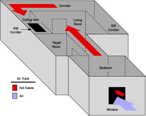
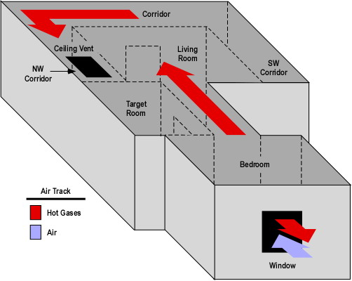
As with the baseline test, two ventilation openings were provided. A ceiling vent in the Northwest Corridor and a window (fitted with glass) in the bedroom (compartment of origin). During the test the window failed due to fire effects and was subsequently fully cleared by the researchers to provide a full window opening for ventilation.

Figure 1. Isometric Illustration of the Test Structure

test_floor_plan_wind

Note: The location of fuel packages in the bedroom and living room is shown on the Floor Plan provided in Wind Driven Fires post.

Experiment 3 Wind Driven Fire

This experiment was one of several that investigated wind driven fire behavior and the effectiveness of a wind control device deployed over the bedroom window to limit inward airflow. The fire was ignited in the bedroom and allowed to develop from incipient to fully developed stage in the bedroom.

The fire progressed in a similar manner as observed in the baseline test described in my earlier post NIST Wind Driven Fire Experiments: Establishing a Baseline. In this experiment the fire involving the initial fuel packages (bed and waste container) and visible smoke layer developed slightly more slowly. However, the bedroom window failed more completely and 11 seconds earlier than in the baseline test.

Almost immediately after the window failed, turbulent flaming combustion filled the bedroom and hot gases completely filled the door between the living room and corridor and were impinging on the opposite wall. At 222 seconds (15 seconds after the window was completely cleared) flames were visible in the corridor and the hollow core wood door in the target room was failing with flames breaching the top corners of the door and a smoke layer developing in the target room. While most of the hot gases and flames were driven through the interior (towards the ceiling vent in the corridor), flames continued to flow out the top of the window opening (against the wind).

At 266 seconds conditions had further deteriorated in all compartments with no visibility in the corridor and increased deterioration of the door to the target room. At this point the air track at the window was completely inward (no flames outside the window).

The wind control device was deployed at 270 seconds. Unfortunately soot on the video cameras lenses precluded a good view of interior conditions. However, video from the thermal imaging camera no longer showed any flow of hot gases into the corridor (only high temperature).

At 330 seconds, shortly after removal of the wind control device flames were visible in the bedroom and the fire quickly progressed to a fully developed state. At 360 seconds, flames were pulsing out the window opening (against the wind).

The experiment was ended at 380 seconds and the fire was extinguished.

Heat Release Rate

As with the baseline test NIST researchers recorded heat release rate data during Experiment 3. As discussed earlier in this post, application of wind increased the amount of oxygen available for combustion and resulting heat release rate in comparison to the baseline test.

Figure 2. Heat Release Rates in Experiments 1 (Baseline) and 3 (Wind Driven)

hrr_experiment3

Note: Adapted from Firefighting Tactics Under Wind Driven Conditions.
Questions: Examine the heat release rate curves in Figure 2 and answer the following questions:

  • What effect did deployment of the wind control device have on HRR and why did this change occur so quickly?
  • How did HRR change when the wind control device was removed and why was this change different from when the window was vented?
  • What factors might influence the extent to which HRR changes when ventilation is increased to a compartment fire in a ventilation controlled burning regime?

Wind Control Device Research and Application

NIST has continued research into the practical application of wind control devices with tests in Chicago and New York involving large apartment buildings and realistic fuel loading. For additional information on these tests and video of wind control device deployment, visit the NIST Wind Driven Fires webpage.

Fire Control Experiments

NIST researchers also conducted a series of experiments in the same structure examining the impact of various fire control tactics. These included application of water using solid stream and combination nozzles (using a 30o fog pattern with continuous application). In addition, they examined the influence of coordinated deployment of a wind control device and low flow water application of water fog). In each of these tests, water was applied from the exterior of the structure through the bedroom window.

Water Fog Application: Experiment 6 involved application of water using a hoseline equipped with a combination nozzle at 90 psi (621 kPa) nozzle pressure, providing a flow rate of 80 gpm (303 lpm). The fog stream was initially applied across the window (no discharge into the bedroom). This had a limited effect on conditions on the interior. When applied into the room, the 30o fog pattern was positioned to almost completely fill the window. This action resulted in a brief increase (approximately 4 MW) and then a dramatic reduction in HRR.

Solid Stream Application: Experiments 7 and 8 involved application of water using a hoseline equipped with a 15/16″ smooth bore nozzle at 50 psi (345 kPa) nozzle pressure, providing a flow rate of 160 gpm (606 lpm).  The solid stream was initially directed at the ceiling and then in a sweeping motion across the ceiling. In Experiment 8, the stream was then directed at burning contents in the compartment. Application of the solid stream had a pronounced effect, dramatically reducing heat release rate in both experiments.

Conditions varied considerably between these three tests (Experiments 6-8). This makes direct comparison of the results somewhat difficult. However, several conclusions can be drawn from the data:

  • Exterior application of water can be effective in reducing HRR in wind driven fires.
  • Both solid stream and fog application can be effective in reducing HRR under these conditions.
  • Continuous application of water fog positioned to nearly fill the inlet opening develops substantial air flow which can increase HRR (this works similar to the process of hydraulic ventilation, but in reverse).
  • A high flow solid stream may be more effective (but not necessarily more efficient) than a lower flow fog pattern if a direct attack on burning contents can be made.

Coordinated WCD Deployment and Water Application: Experiments 4 and 5 involved evaluations of anti-ventilation and water application using a small wind control device and 30 gpm (113.6 lpm) spray nozzle from under the wind control device. The effectiveness of the wind control device was similar to other anti-ventilation tests and application of low flow water fog resulted in continued decrease in HRR throughout the experiment.

Ed Hartin, MS, EFO, MIFireE, CFO

References

Madrzykowski, D. & Kerber, S. (2009). Fire Fighting Tactics Under Wind Driven Conditions. Retrieved (in four parts) February 28, 2009 from http://www.nfpa.org/assets/files//PDF/Research/Wind_Driven_Report_Part1.pdf; http://www.nfpa.org/assets/files//PDF/Research/Wind_Driven_Report_Part2.pdf;http://www.nfpa.org/assets/files//PDF/Research/Wind_Driven_Report_Part3.pdf;http://www.nfpa.org/assets/files//PDF/Research/Wind_Driven_Report_Part4.pdf.
NIST Wind Driven Fire Experiments:
Anti-Ventilation-Wind Control Devices

Monday, March 9th, 2009

My last post asked a number of questions focused on results of baseline compartment fire tests conducted by the National Institute for Standards and Technology (NIST) as part of a research project on  Firefighting Tactics Under Wind Driven Conditions.  This post looks at the answers to these questions and continues with an examination of NIST’s experiments in the application of wind control devices for anti-ventilation.
Questions

Generally being practically focused people, firefighters do not generally dig into research reports. However, the information on the baseline test conducted by NIST raised several interesting questions that have direct impact on safe and effective firefighting operations. First consider possible answers to the questions and then why this information is so important (the “So what?”!).

Figure 1. Heat Release Rate Comparison

hrr_comparison

Note: Adapted from Firefighting Tactics Under Wind Driven Conditions.
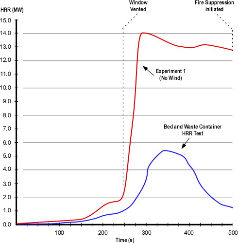
Heat Release Rate (HRR) Questions: Examine the heat release rate curves in Figure 1 and answer the following questions:

  • Why are these two HRR curves different shapes?
  • In each of these two cases, what might have influenced the rate of change (increase or decrease in HRR) and peak HRR?
  • What observations can you make about conditions inside the test structure and heat release rate (in particular, compare the HRR and conditions at approximately 250 and 350 seconds)?

Answers: The HRR test for the bed and waste container was conducted under fuel controlled conditions (oxygen supply was not restricted). The higher HRR in the compartment fire experiment results from increased fuel load (e.g., additional furniture, carpet). After reaching its peak, HRR in the compartment fire drops off slowly as the fire becomes ventilation controlled and the fire continues in a relatively steady state of combustion (limited by the air supplied through the lower portion of the bedroom window)

The rate of change in heat release rate under fuel controlled conditions is dependent on the characteristics and configuration of the fuel.  However, in the case of the compartment fire test, the rate of change is also impacted by limited ventilation. As illustrated in the compartment fire curve, the fire quickly became ventilation controlled and HRR rose slowly until the window failed and was fully cleared by researchers.

At 250 seconds (when the window was vented) HRR rose extremely rapidly as the fire in the bedroom rapidly transitioned from the growth through flashover to fully developed stage. At 350 seconds the fire had again become ventilation controlled and was burning in a relatively steady state limited by the available oxygen.

The fully developed fire in the bedroom also became ventilation controlled due to limited ventilation openings, resulting in HRR leveling off with relatively steady state combustion based on the available oxygen.

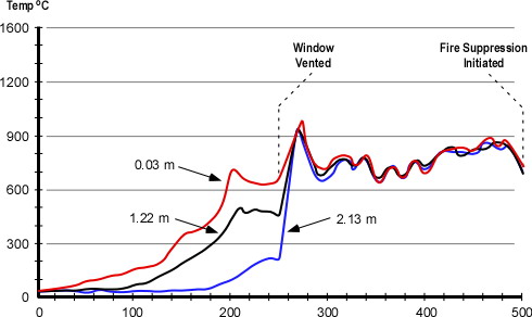
Figure 2. Bedroom Temperature

bedroom_temp

Note: Adapted from Firefighting Tactics Under Wind Driven Conditions.
Temperature Questions: Examine the temperature curves in Figure 2 and answer the following questions:

  • What can you determine from the temperature curves from ignition until approximately 250 seconds?
  • How does temperature change at approximately 250 seconds? Why did this change occur and how does this relate to the data presented in the HRR curve for Experiment 1 (Figure 1)?
  • What happens to the temperature at the upper, mid, and lower levels after around 275 seconds? Why does this happen?

Answers: Temperature at the upper levels of the compartment increased much more quickly than at the lower level and conditions in the compartment remained thermally stratified until the ceiling temperature exceeded 600o C. At approximately 250 seconds, the compartment flashed over resulting in a rapid increase in temperature at mid and lower levels. This change correlates with the rapid increase in HRR occurring at approximately 250 seconds in Figure 1. Turbulent, ventilation controlled combustion resulted in a loss of thermal layering with temperatures in excess of 600o C from ceiling to floor. At around 275 seconds.

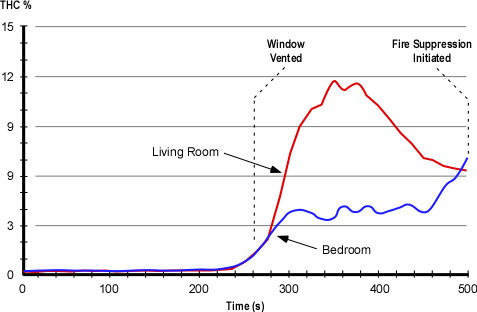
Figure 3. Total Hydrocarbons at the Upper Level

upper_level_thc

Note: Adapted from Firefighting Tactics Under Wind Driven Conditions.
Total Hydrocarbons (THC) Questions: Examine the THC curves in Figure 3 and answer the following questions:

  • Why did the THC concentration in the living room rise to a higher level than in the bedroom?
  • Why didn’t the gas phase fuel in the living room burn?
  • How did the concentration of THC in the bedroom reach approximately 4%? Why wasn’t this gas phase fuel consumed by the fire?

Answers: Oxygen entering the compartments through the window was being used by combustion occurring in the bedroom. Low oxygen concentration limited combustion in the living room and allowed accumulation of a higher concentration of unburned fuel. While the oxygen concentration in the bedroom was higher, the fire was still ventilation controlled and not all of the gas phase fuel was able to burn inside this compartment.

So What?

What do the answers to the preceding questions mean to a company crawling down a dark, smoky hallway with a hoseline or making a ventilation opening at a window or on the roof?

Emergency incidents do not generally occur in buildings equipped with thermocouples, heat flux gages, gas monitoring equipment, and pre-placed video and thermal imaging cameras. Understanding the likely sequence of fire development and influencing factors is critical to not being surprised by fire behavior phenomena. These tests clearly illustrated how burning regime (fuel or ventilation controlled) impacts fire development and how changes in ventilation can influence fire behavior. The total hydrocarbon concentration and ventilation controlled combustion in the living room would present a significant threat in an emergency incident. How might conditions change if the fire in the bedroom was controlled and oxygen concentration began to increase? Ignition of the gas phase fuel in this compartment could present a significant threat (see Fire Gas Ignitions) or even prove deadly (future posts will examine the deaths of a captain and engineer in a fire gas ignition in California).

Anti-Ventilation

For years firefighters throughout the United States have been taught that ventilation is “the planned and systematic removal of heat, smoke, and fire gases, and their replacement with fresh air”. This is not entirely true! Ventilation is simply the exchange of the atmosphere inside a compartment or building with that which is outside. This process goes on all the time. What we have thought of as ventilation, is actually tactical ventilation. This term was coined a number of years ago by my friend and colleague Paul Grimwood (London Fire Brigade, retired). It is essential to recognize that there are two sides to the ventilation equation, one is removal of the hot smoke and fire gases and the other is introduction of air. Increased ventilation can improve tenability of the interior environment, but under ventilation controlled conditions will result in increased heat release rate.

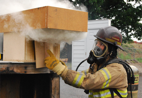
Another tactic change the ventilation profile and influence fire behavior and conditions inside the building is to confine the smoke and fire gases and limit introduction of air (oxygen) to the fire. Firefighters in the United States often think of this as confinement, but I prefer the English translation of the Swedish tactic, anti-ventilation. This is the planned and systematic confinement of heat, smoke, and fire gases and exclusion of fresh air. The concept of anti-ventilation is easily demonstrated by limiting the air inlet during a doll’s house demonstration (see Figure 4). Closing the inlet dramatically reduces heat release rate and if sustained, can result in extinguishment.

Figure 4. Anti-Ventilation in a Doll’s House Demonstration

doll_house_door

For a more detailed discussion of the relationship between ventilation and heat release rate see my earlier post on Fuel and Ventilation.

Air Track and Influence of Wind

Air track (movement of smoke and air under fire conditions) is influenced by differences in density between hot smoke and cooler air and the location of ventilation openings. However, wind is an often unrecognized influence on compartment fire behavior. Wind direction and speed can influence movement of smoke, but more importantly it can have a dramatic influence on introduction of air to the fire.

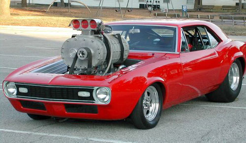
While the comparison is not perfect, the effects of wind on a compartment fire can be similar to placing a supercharger on an internal combustion engine (see Figure 5). Both dramatically increase power (energy released per unit of time).

Figure 5. Influence of Wind

supercharger

NIST Wind Control Device Tests

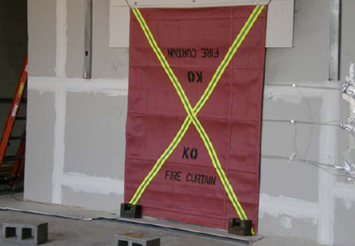
As discussed in Wind Driven Fires, the effects of wind on compartment fire behavior can present a significant threat to firefighters and has resulted in a substantive number of line-of-duty deaths. In their investigation of potential tactical options for dealing with wind driven fires, NIST researchers examined the use of wind control devices (WCD) to limit introduction of air through building openings (specifically windows in the fire compartment in a high-rise building) as illustrated in Figure 6.

Figure 6. Small Wind Control Device

wcd_small

Note: Photo from Firefighting Tactics Under Wind Driven Conditions.
Questions

Give some thought to how wind can influence compartment fire behavior and how a wind control device might mitigate that influence.

  • How would a strong wind applied to an opening (such as the bedroom window in the NIST tests) influence fire behavior in the compartment of origin and other compartments in the structure?
  • How would a wind control device deployed as illustrated in Figure 5 influence fire behavior?
  • While the wind control device illustrated in Figure 5 was developed for use in high-rise buildings, what applications can you envision in a low-rise structure?
  • What other anti-ventilation tactics could be used to deal with wind driven fires in the low-rise environment?

The Story Continues…

My next post will address the answers to these questions (please feel free to post your thoughts) and examine the results of NIST’s tests on the use of wind control devices for anti-ventilation.

References

Madrzykowski, D. & Kerber, S. (2009). Fire Fighting Tactics Under Wind Driven Conditions. Retrieved (in four parts) February 28, 2009 from http://www.nfpa.org/assets/files//PDF/Research/Wind_Driven_Report_Part1.pdf; http://www.nfpa.org/assets/files//PDF/Research/Wind_Driven_Report_Part2.pdf;http://www.nfpa.org/assets/files//PDF/Research/Wind_Driven_Report_Part3.pdf;http://www.nfpa.org/assets/files//PDF/Research/Wind_Driven_Report_Part4.pdf.
Ed Hartin, MS, EFO, MIFireE, CFO

NIST Wind Driven Fire Experiments:
Establishing a Baseline

Thursday, March 5th, 2009

My last post introduced a National Institute for Standards and Technology research project examining firefighting tactics for wind driven structure fires (particularly those occurring in high-rise buildings). The report on this research Firefighting Tactics Under Wind Driven Conditions contains a tremendous amount of information on this series of experiments including heat release rate, heat flux, pressure, velocity, and gas concentrations during each of the tests along with time sequenced still images (video and infrared video capture).

This post will examine the initial test used to establish baseline conditions for evaluation of wind driven fire conditions and tactics. Readers are encouraged to download a copy of the report and dig a bit deeper!

Test Conditions

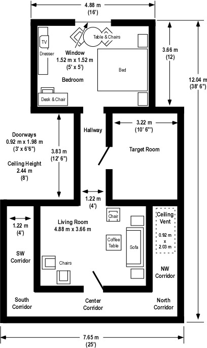
In Wind Driven Fires, I provided an overview of the multi-compartment test structure and fuel load used for this series of experiments. To quickly review, the test structure was comprised of three compartments; Bedroom, Target Room (used to assess tenability in a compartment adjacent to the ventilation flow), and Living Room, along with an interconnecting hallway (between the Bedroom and Living Room) and exterior corridor. Fuel load consisted of typical residential furnishings in the bedroom and living room along with carpet and carpet pad throughout the structure. The target room (used to assess tenability in a potential place of refuge for occupants or firefighters) did not contain any furnishings. Different types of doors (metal, hollow core wood, etc.) were used in the tests to evaluate performance under realistic fire conditions.

Two ventilation openings were provided, a ceiling vent in the Northwest Corridor (providing a flow path from the involved compartment(s) into the corridor) and a window (fitted with glass) in the compartment of origin. During the fire tests, the window failed due to differential heating (of the inner and outer surface of the glass) and was subsequently removed by researchers to provide the full window opening for ventilation.

Figure 1. Isometric Illustration of the Test Structure

isometric_floor_plan

Note: The location of fuel packages in the bedroom and living room is shown on the Floor Plan provided in Wind Driven Fires post.

The structure was constructed under a large oxygen consumption calorimetry hood which allowed measurement of heat release rate (once products of combustion began to exit the ceiling vent). In addition, thermocouples, heat flux gages, pressure transducers, and bidirectional probes were used to measure temperature, heat flux, pressure, and gas flow within and out of the structure. Gas sampling probes were located at upper and lower levels, (0.61 m (2′) and 1.83 m (6′) below the ceiling respectively) in the bedroom and living room. Researchers measured oxygen, carbon dioxide, carbon monoxide, and total hydrocarbon concentration during each test.

Experiment 1 Baseline Test

This experiment was different than the others in the series as no external wind was applied to the structure. The fire was ignited in the bedroom and allowed to develop from incipient to fully developed stage in the bedroom.

After 60 seconds the fire had extended from the trash can (first fuel package ignited) to the bed and chair. At this point a visible smoke layer had developed in the bedroom.

120 seconds after ignition, the smoke layer had reached a thickness of 1.2 m (4′) in the bedroom, hallway, and living room. At this point, smoke had just started to enter the corridor. Conditions in the target room were tenable with little smoke infiltration.

At 180 seconds after ignition, the smoke layer was 1.5 m (5′) deep and had extended from the living room into the corridor. Flames from the bed and chair had reached the ceiling. Hot smoke and clear air was well stratified with a distinct boundary between upper and lower layers. Smoke had begun to infiltrate at the top of the door to the target room.

240 seconds after ignition the window started to fail due to flame impingement and the smoke layer extended from ceiling to floor in the bedroom. The smoke layer in the living room had reached a depth of 2.1 m (7′) from the ceiling. Temperature in the corridor remained well stratified.

248 seconds after ignition the researchers cleared the remaining glass from the window to provide a full opening for ventilation. As the glass was removed, the size of the fire in the bedroom and flames exiting the window increased. A thin smoke layer had developed at ceiling level in the target room.

At 300 seconds, flames had begun to burn through the wood, hollow core door to the target room and flaming combustion is also visible in the hallway at the bottom of this door. Flames continued to exit the top 2/3 of the window.

360 seconds into the test, the fire in the bedroom reached steady state (post-flashover), ventilation controlled combustion. The door to the target room has burned through with a dramatic increase in temperature as the room fills with smoke.

Suppression using fixed sprinklers and a hoseline began at 525 seconds.

Fire development during this experiment was not particularly remarkable with conditions that could typically be expected in a residential occupancy. So, what can we learn from this test?

Heat Release Rate

NIST researchers examined the heat release rate of individual fuel packages and combinations of fuel packages prior to the compartment fire tests. These tests conducted in an oxygen consumption calorimeter were performed with the fire in a fuel controlled burning regime. Figure 2 illustrates the heat release rate from the combination of waste container and bed fuel packages and the heat release rate generated during Experiment 1 (in which the initial fuel packages ignited were the waste container and bed located inside the bedroom.

Figure 2. Heat Release Rate Comparison

hrr_comparison

Note: Adapted from Firefighting Tactics Under Wind Driven Conditions.
Questions: Examine the heat release rate curves in Figure 2 and answer the following questions:

  • Why are these two HRR curves different shapes?
  • In each of these two cases, what might have influenced the rate of change (increase or decrease in HRR) and peak HRR?
  • What observations can you make about conditions inside the test structure and heat release rate (in particular, compare the HRR and conditions at approximately 250 and 350 seconds)?

Temperature

During the experiments temperature was measured in each of the compartments at multiple levels. Figure 3 illustrates temperature conditions in the bedroom at 0.03 m (1″), 1.22 m (4′) and 2.13 m (7′) down from the ceiling during Experiment 1.

Figure 3. Bedroom Temperature

bedroom_temp

Note: Adapted from Firefighting Tactics Under Wind Driven Conditions. Position.
Questions: Examine the temperature curves in Figure 3 and answer the following questions:

  • What can you determine from the temperature curves from ignition until approximately 250 seconds?
  • How does temperature change at approximately 250 seconds? Why did this change occur and how does this relate to the data presented in the HRR curve for Experiment 1 (Figure 2)?
  • What happens to the temperature at the upper, mid, and lower levels after around 275 seconds? Why does this happen?

Total Hydrocarbons

In addition to HRR and temperature, researchers measured gas concentrations inside the compartments at the upper and lower levels. Figure 4 shows the concentration (in % volume) of total hydrocarbons in the bedroom and living room. Concentration of total hydrocarbons is a measure of gas phase fuel (pyrolysis products) in the upper layer.

Figure 4. Total Hydrocarbons at the Upper Level

upper_level_thc

Note: Adapted from Firefighting Tactics Under Wind Driven Conditions. Position.
Questions: Examine the THC curves in Figure 4 and answer the following questions:

  • Why did the THC concentration in the living room rise to a higher level than in the bedroom?
  • Why didn’t the gas phase fuel in the living room burn?
  • How did the concentration of THC in the bedroom reach approximately 4%? Why wasn’t this gas phase fuel consumed by the fire?

The Story Continues…

My next post will address the answers to these questions (please feel free to post your thoughts) and provide an overview of NIST’s initial tests on the use of wind control devices for anti-ventilation.

Ed Hartin, MS, EFO, MIFireE, CFO

Wind Driven Fires

Monday, March 2nd, 2009

Weather, Topography, and Fuel

In S-190 Introduction to Wildland Fire Behavior, firefighters learn that weather, topography, and fuel and the principal factors influencing fire behavior in the wildland environment. How might this important concept apply when dealing with fires in the built environment? Factors influencing compartment fire behavior have a strong parallel to those in the wildland environment. Principal influences on compartment fire behavior include fuel, configuration (of the compartment and building), and ventilation.

Wind Driven Compartment Fires

As buildings are designed to minimize the influence of weather on their contents and occupants, weather is not generally considered a major factor in compartment fires. However, this is not always the case. As wildland firefighters recognize, wind can be a major influence on fire behavior and strong winds present a significant threat of extreme fire behavior.

Under fire conditions, unplanned ventilation involves all changes influencing exhaust of smoke, air intake, and movement of smoke within the building that are not part of the incident action plan. These changes may result from the actions of exiting building occupants, fire effects on the building (e.g., failure of window glass), or a wide range of other factors.

Changes in ventilation can increase fire growth and hot smoke throughout the building. Failure of a window in the fire compartment in the presence of wind conditions can result in a significant and rapid increase in heat release. If this is combined with open doors to corridors, unprotected stairwells, and other compartments, wind driven fire conditions have frequently resulted in firefighter injuries and fatalities (see Additional Reading).

NIST Research on Wind Driven Fires

From November 2007 to January 2008, the National Institute of Standards and Technology conducted a series of experiments examining firefighting tactics dealing with wind driven compartment fires. The primary focus of this research was on the dynamics of fire growth and intensity and the influence of ventilation and fire control strategies under wind driven fire conditions. The results of these experiments are presented in Fire Fighting Tactics Under Wind Driven Conditions, published by The Fire Protection Research Foundation.

Tests conducted at NIST’s Large Fire Test Facility (see Figure 1) included establishment of baseline heat release data for the fuels (bed, chairs, sofa, etc), full scale fire tests under varied conditions (e.g., no wind, wind), and experiments involving control of the inlet opening and varied methods of external water application.

Figure 1. NIST Large Fire Test Facility

nist_large_fire_facility

Note: Photo adapted from Firefighting Tactics Under Wind Driven Conditions.
The objectives of this study were:

  • To understand the impact of wind on a structure fire fueled with residential furnishings in terms of temperature, heat flux, heat release rate, and gas concentrations
  • To quantify the impact of several novel firefighting tactics on a wind driven structure fire
  • Improve firefighter safety

After conducting a series of tests to determine the heat release rate characteristics of the fuels to be used for the full scale tests, NIST conducted eight full scale experiments to examine the impact of wind on fire spread through the multi-room test structure (see Figure 2) and examine the influence of anti-ventilation using wind control devices and the impact of external water application.

Multi-Room Test Structure

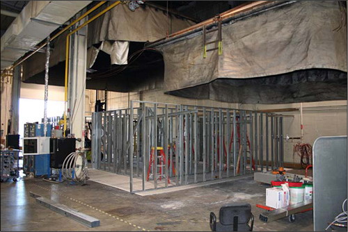
All tests were conducted under the 9 m (30′) x 12 m (40′) oxygen consumption calorimetry hood at the NIST Large Fire Test Facility. The test structure was comprised of three compartments; Bedroom, Target Room (used to assess tenability in a compartment adjacent to the ventilation flow), and Living Room, along with an interconnecting hallway and exterior hallways. A large mechanical fan was positioned 7.9 m (26′) away from the window in the bedroom of the test structure (see Figure 2) to provide consistent wind conditions for the experiments.

Figure 2. Configuration of the Multi-Room Test Structure

test_floor_plan

Note: Adapted from Firefighting Tactics Under Wind Driven Conditions.

The structure was framed with steel studs and wood truss joist I-beams (TJIs) used to support the ceiling. The interior of the compartments were lined with three layers of 13 mm (1/2″) gypsum board. Multiple layers of gypsum board were used to provide the durability required for repetitive experiments (the inner layer was replaced and repairs made to other layers as needed between experiments).

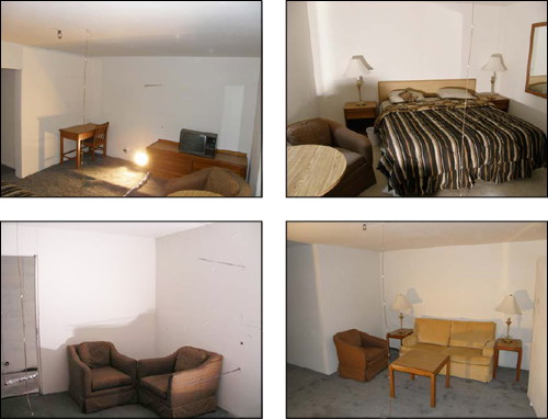
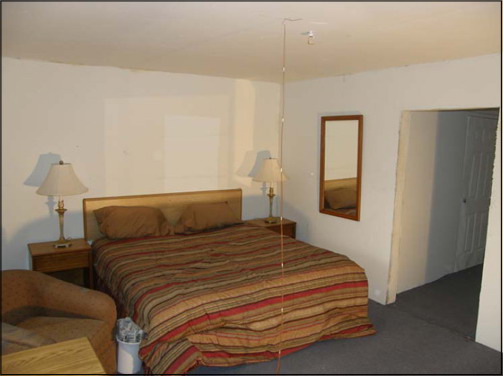
Used furnishings were purchased from a hotel liquidator to obtain 10 sets of similar furniture to use in the heat release rate and full-scale, multi-compartment experiments. Fuel used in the tests included furniture, nylon carpet, and polyurethane carpet padding (the position major furniture items are illustrated in Figures 2 and 3).  Fuel load was 348.69 kg (768.73 lbs) in the bedroom, 21.5 kg (47.40 lbs) in the hallway, and 217.6 kg (479.73 lbs) in the living room (no contents were placed in the target room).

Figure 3. Bedroom and Living Room Fuel Load

contents

Note: Photos adapted from Firefighting Tactics Under Wind Driven Conditions.

NIST researchers conducted a series of eight full-scale, multi-compartment fire tests. In each case, a fire was started in the Bedroom using a plastic trash container placed next to the bed (see Figure 3).

Figure 3. Placement of the Trash Container

placement_trash_container

Note: Photos adapted from Firefighting Tactics Under Wind Driven Conditions.

Experiments

The eight tests provided the opportunity to study the dynamics of wind driven compartment fires and several different approaches to limiting the influence of air intake and controlling the fire.

Experiment 1: This test was performed to establish baseline conditions with no wind

Experiment 2: Evaluation of anti-ventilation using a large wind control device placed over the window

Experiment 3: Evaluation of anti-ventilation using a large wind control device placed over the window (second test with a longer pre-burn before deployment of the wind control device).

Experiment 4: Evaluation of anti-ventilation and water application using a small wind control device and 30 gpm (113.6 lpm) spray nozzle from under the wind control device.

Experiment 5: Evaluation of anti-ventilation and water application using a small wind control device and 30 gpm (113.6 lpm) spray nozzle from under the wind control device (second test with a lower wind speed)

Experiment 6: No wind control device, application of water using a hoseline equipped with a combination nozzle at 90 psi (621 kPa) nozzle pressure, providing a flow rate of 80 gpm (303 lpm).

Experiment 7: No wind control device, application of water using a hoseline equipped with a 15/16″ smooth bore nozzle at 50 psi (345 kPa) nozzle pressure, providing a flow rate of 160 gpm (606 lpm) (test was conducted with the living room corridor door closed).

Experiment 8: No wind control device, application of water using a hoseline equipped with a 15/16″ smooth bore nozzle at 50 psi (345 kPa) nozzle pressure, providing a flow rate of 160 gpm (606 lpm) (second test with the living room corridor door open).

Note: The nozzles for these tests (100 gpm at 100 psi combination nozzle and 15/16″ solid stream nozzle were selected as to be representative of those used by the fire service in the United States (personal correspondence, S. Kerber, February 28, 2009). However, it is important to note that in comparing the results, that the combination nozzle was under pressurized (80 psi, rather than 100 psi) resulting in large droplet size. In addition, the 100 gpm flow rate was 50% of that applied through the solid stream nozzle and is likely considerably lower than the flow capability of combination nozzles typically used with 1-3/4″ (45 mm) hose.

Important Findings

The first experiment was conducted without any external wind or tactical intervention. The baseline data generated during this test was critical to evaluating the outcome of subsequent experiments and demonstrated a number of concepts that are critical to firefighter safety:

Smoke is fuel. A ventilation limited (fuel rich) condition had developed prior to the failure of the window. Oxygen depleted combustion products containing carbon dioxide, carbon monoxide and unburned hydrocarbons, filled the rooms of the structure. Once the window failed, the fresh air provided the oxygen needed to sustain the transition through flashover, which caused a significant increase in heat release rate.

Venting does not always equal cooling. In this experiment, post ventilation temperatures and heat fluxes all increased, due to the ventilation induced flashover.

As discussed in early posts, Fuel & Ventilation and Myth of the Self Vented Fire understanding the relationship between oxygen and heat release rate, the hazards presented by ventilation controlled fires, and the influence of ventilation on fire development is critical to safe and effective fireground operations.

Fire induced flows. Velocities within the structure exceeded 5 m/s (11 mph), just due to the fire growth and the flow path that was set-up between the window opening and the corridor vent.

Avoid the flow path. The directional nature of the fire gas flow was demonstrated with thermal conditions, both temperature and heat flux, which were twice as high in the “flow” portion of the corridor as opposed to the “static” portion of the corridor in Experiment 1 [not wind driven]. Thermal conditions in the flow path were not consistent with firefighter survival.

Previous posts have presented case studies based on incidents in Loudoun County Virginia and Grove City, Pennsylvania in which convective flow was a significant factor rapid fire progress that entrapped and injured firefighters, in one case fatally. Previous NIST research investigating a multiple line-of-duty death that occurred in a townhouse fire at 3146 Cherry Road in Washington, DC in 1999 also emphasized the influence of flow path on fire conditions and tenability.

More to Follow

Subsequent posts will examine the NIST wind driven fire tests in greater detail.

Ed Hartin, MS, EFO, MIFireE, CFO

References

Madrzykowski, D. & Kerber, S. (2009). Fire Fighting Tactics Under Wind Driven Conditions. Retrieved (in four parts) February 28, 2009 from http://www.nfpa.org/assets/files//PDF/Research/Wind_Driven_Report_Part1.pdf; http://www.nfpa.org/assets/files//PDF/Research/Wind_Driven_Report_Part2.pdf;http://www.nfpa.org/assets/files//PDF/Research/Wind_Driven_Report_Part3.pdf;http://www.nfpa.org/assets/files//PDF/Research/Wind_Driven_Report_Part4.pdf.

Madrzykowski, D. & Vettori, R. (2000). Simulation of the Dynamics of the Fire at 3146 Cherry Road NE, Washington D.C., May 30, 1999. Retrieved March 1, 2009 from http://fire.nist.gov/CDPUBS/NISTIR_6510/6510c.pdf

Additional Reading

The following investigative reports deal with firefighter line of duty deaths involving wind driven fire events during structural firefighting.

National Institute for Occupational Safety and Health (NIOSH). (1999). Death in the line of duty, Report F99-01. Retrieved February 28, 2009 from http://www.cdc.gov/niosh/fire/pdfs/face9901.pdf

National Institute for Occupational Safety and Health (NIOSH). (1999). Death in the line of duty, Report F98-26. Retrieved February 28, 2009 from http://www.cdc.gov/niosh/fire/pdfs/face9826.pdf

National Institute for Occupational Safety and Health (NIOSH). (2002). Death in the line of duty, Report F2001-33. Retrieved February 28, 2009 from http://www.cdc.gov/niosh/fire/pdfs/face200133.pdf

National Institute for Occupational Safety and Health (NIOSH). (2007). Death in the line of duty, Report F2005-03. Retrieved February 28, 2009 from http://www.cdc.gov/niosh/fire/pdfs/face200503.pdf

National Institute for Occupational Safety and Health (NIOSH). (2008). Death in the line of duty, Report F2007-12. Retrieved February 28, 2009 from http://www.cdc.gov/niosh/fire/pdfs/face200712.pdf

Prince William County Department of Fire and Rescue (2007). Line of duty investigative report: Technician I Kyle Wilson. Retrieved February 28, 2009 from http://www.pwcgov.org/default.aspx?topic=040061002930004566

Texas State Fire Marshal’s Office. (2001). Firefighter Fatality Investigation, Investigation Number 02-50-10. Retrieved February 28, 2009 from http://www.tdi.state.tx.us/reports/fire/documents/fmloddjahnke.pdf

Hazard of Ventilation Controlled Fires

Thursday, October 9th, 2008

In the Grading the Fireground on a Curve, published in the September issue of Firehouse magazine, Battalion Chief Mark Emery warned of the hazards of assuming that limited volume and velocity of visible smoke indicates a growth stage fire. He correctly identified that compartment fires may enter the decay phase as fuel is consumed or due to a lack of oxygen.

Emery cites National Institute for Occupational Safety and Health (NIOSH) Death in the Line of Duty reports 98-F07 and F2004-14, in which firefighters initiated offensive fire attack in commercial buildings and encountered rapidly deteriorating fire conditions due to changes in the ventilation profile. Concluding the introduction to his article, Emery observes “Unless you know which side of the fire growth curve you are entering, advancing into zero-visibility conditions is really a bad idea”.

I agree with BC Emery’s basic premise that appearances can be deceiving. However, this article points to two interrelated issues. The hazards presented by ventilation controlled fires and the dangerous conditions presented by enclosed buildings. In Smoke Burns,originally published on Firehouse.com I discussed the hazards of ventilation controlled fire and the relationship of burning regime to extreme fire behavior phenomena such as flashover and backdraft. The hazards presented by ventilation controlled fires are compounded when the fire occurs in an enclosed structure (a building with limited means of access and egress). Captain Willie Mora has written extensively on Enclosed Structure Disorientation on Firehouse.com.

BC Emery illustrated how appearances can be deceiving using data and still images from a full scale fire test in a warehouse in Phoenix, Arizona conducted by the National Institute for Standards and Technology (NIST). NIST conducted these tests as part of a research project on structural collapse. However, the video footage and temperature data from this test is extremely useful in studying the influence of ventilation on fire behavior and fire behavior indicators (Building, Smoke, Air Track, Heat, and Flame (B-SAHF)). The full report and video from this test is available on-line from the NIST Building Fire Research Laboratory (BFRL).

As an oxidation reaction, combustion requires oxygen to transform the chemical potential energy in fuel to thermal energy. If a developing compartment fire becomes ventilation controlled, with heat release rate limited by the oxygen available in the compartment, pyrolysis will continue as long as temperature in the compartment is above several hundred degrees Celsius. Pyrolysis products in smoke are gas phase fuel ready to burn. Increased ventilation at this point, may cause the fire to quickly transition to the fully developed stage (ventilation induced flashover). However, if the fire continues to burn in a ventilation controlled state and the concentration of gas phase fuel (pyrolysis products and flammable products of incomplete combustion) increases sufficiently, increased ventilation may result in a backdraft.

I take issue with BC Emery’s illustration of the growth side of the fire development curve as the value side of the cure and the decay side of the curve as the no value side of the curve. Depending on resources, a fire on the growth side of the curve may exceed the offensive fire control capability of the fire department. Conversely, a fire on the decay side of the curve which is limited to a single compartment or series of compartments may be effectively controlled using an appropriate tactics in an offensive strategic mode. However, Emery’s discussion of the more subtle indicators of burning regime that may warn firefighters of a ventilation controlled fire is right on track. For more information on fire behavior indicators and fire development, see Fire Behavior Indicators and Fire Development Parts I and II on Firehouse.com.

Ed Hartin, MS, EFO, MIFireE, CFO