Archive for the ‘Fire Control’ Category

Gas Cooling: Part 2

Sunday, August 22nd, 2010

In a compartment fire, the upper layer can present significant hazards to firefighters, including potential for ignition and energy transfer). My last post, Gas Cooling, began an examination of the science behind gas cooling, application of water fog into the upper layer to reduce the potential for ignition and thermal hazards presented by the hot gases.

Figure 1. Energy Transfer Required for Cooling
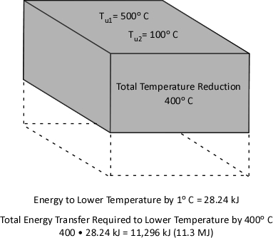
With a specific heat of 4.2 kJ/kg and latent heat of vaporization of 2260 kJ/kg, it takes considerable energy to raise the temperature of water to its boiling point of 100o C and change it from liquid to gas phase steam. Smoke on the other hand has a specific heat of 1.0 kJ/kg, indicating that in comparison with water; much less energy is required to change its temperature. As explained in Gas Cooling, 11.3 MJ must be transferred from the upper layer of this compartment to water applied for cooling in order to lower the temperature of the upper layer in a compartment from 500o C to 100o C (see Figure 1). It is important to remember that the energy required to cool the upper layer is dependent on the mass of hot smoke and air in the upper layer. This value will vary with the size of the compartment and the temperature of the hot gases.

When starting out on this examination of gas cooling, we posed two questions:

  • How much water is required to cool the upper layer from 500o C to 100o C?
  • Why doesn’t the volume of the upper layer increase when water applied to cool the hot gases is turned to steam?

The answers to these questions are interrelated. First, let’s look at the amount of water required.

Water Required for Cooling

When water is applied for fire control and extinguishment, energy is transferred from materials that have a temperature higher than that of the water to raise the temperature of the water and to change it from liquid phase to gas phase.

The theoretical cooling capacity (TCC) of water is 2.6 MJ/kg. This value is based on heating a kilogram of water from 20o C to 100o C (0.3 MJ/kg) and vaporizing it completely into steam (2.3 MJ/kg).

Dividing the energy that must be transferred from the upper layer by the TCC calculates the amount of water that would theoretically be required to cool the upper layer from 500o C to 100o C if the energy transfer and conversion of water to steam was 100% efficient. If this was the case, the upper layer could be cooled to 100o C by applying 4.35 kg of water. Given the density of water at 20o C of approximately 1.0 kg/l, this would be a volume of approximately 4.35 liters. However, this assumes instantaneous heat transfer and 100% efficiency in conversion of water to the gas phase. Neither of which is possible in the real world!

Experimental data (Hadjisophocleous & Richardson, 2005; Särdqvist, S., 1996) has shown that the cooling efficiency of water in both laboratory experiments and actual firefighting operations ranges from 0.2 to 0.6. Särdqvist (1996) suggests that an efficiency factor of 0.2 be used for interior fog nozzles. Barnett (as cited in Grimwood, 2005) suggests that an efficiency factor of 0.5 be used for solid or straight stream application and 0.75 for fog application. In actuality, the efficiency of water application varies considerably with the design of the nozzle, skill of the nozzle operator, and a range of other factors. For our examination of gas cooling, we will use an efficiency factor of 0.6 (60%).

Multiplying the TCC of water by 0.6 adjusts the cooling capacity to account for the fact that some of the water applied into the hot gas layer will not turn to steam while passing through the hot gas layer. Some of the droplets will pass through the gas layer and vaporize on contact with hot surfaces (more on this later) and others will fall to the floor, with increased temperature, but remaining in liquid form.

Figure 2. Adjusted Cooling Capacity of Water
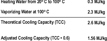
Dividing the 11.3 MJ of energy that must be transferred from the upper layer of the compartment by an Adjusted Cooling Capacity (ACC) of 1.56 MJ/kg determines that 7.2 kg (7.2 liters) of water are required to lower its temperature from 500o C to 100o C.

Figure 3 illustrates common flow rates from combination nozzles, Adjusted Cooling Capacity (ACC) and time required to apply the 7.2 kg of water necessary to cool the upper layer of the compartment from 500o C to 100o C.

Figure 3. Flow Rate, Adjusted Cooling Capacity, and Application Duration
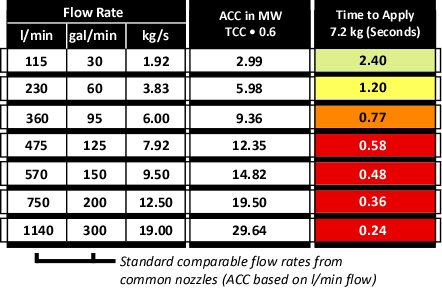
As illustrated in Figure 3, if water is applied at 115 l/min (30 gal/min), several short pulses will provide sufficient water application. If the flow rate is increased to 230 l/min, a single pulse is likely to be sufficient. However, if the flow rate is increased further, it is likely that excessive water will be applied. In addition, droplet size increases with flow rate, reducing efficiency.

All Models are Wrong!

This examination of gas cooling provided a simple example of how much water is required to cool the upper layer in a given compartment. While this explanation provides a good way to understand how gas cooling works, it is incomplete. Box and Draper (1987, p. 424)observe that “all models are wrong, but some are useful”. The following factors add quite a bit of complexity to examination of gas cooling:

  • The energy that must be transferred from the upper layer is dependent on the mass of the hot gases and their temperature.
  • Not all of the water applied vaporizes in the upper layer (some droplets travel through the hot gases and vaporize on contact with hot surfaces and others drop to the floor without completely vaporizing).
  • Temperature of the hot gases in the upper layer is not uniform (as assumed in two layer models).
  • Ongoing combustion and energy transfer from hot compartment linings add energy to the hot gas layer.
  • Convection and gravity current influence the movement of hot and cool gases, making conditions dynamic rather than static.

While our model of gas cooling is wrong, I believe that it is useful. Firefighters do not calculate the volume of water required to cool the hot gas layer on the fireground. However, it is important to understand how flow rate and duration impact on effectiveness and efficiency.

Important!

Remember that this example involved gas cooling in a single compartment with static conditions. The flow rate and/or duration of application for fires in larger compartments or direct attack on burning fuel may be quite different.

What’s Next?

One question remains in our examination of gas cooling. Why doesn’t the volume of the upper layer increase when water applied for gas cooling turns to steam? This will be the focus of the third post in this series.

Ed Hartin, MS, EFO, MIFireE, CFO

References

Box, G. & Draper, R (1987). Empirical Model-Building and Response Surfaces. New York: Wiley.

Hadjisophocleous, G.V. & Richardson, J.K. (2005). Water flow demands for firefighting. Fire Technology 41, p. 173-191.

Särdqvist, S. (1996) An Engineering Approach To Fire-Fighting Tactics Sweden, Lund University, Department of Fire Safety Engineering

Svennson, S. (2002). The operational problem of fire control (Report LUTVDG/TVBB-1025-SE). Sweden, Lund University, Department of Fire Safety Engineering.

Grimwood, P. (2005). Firefighting Flow Rate: Barnett (NZ) – Grimwood (UK) Formulae. Retrieved January 26, 2008 from http://www.fire-flows.com/FLOW-RATE%20202004.pdf

Gas Cooling

Saturday, August 14th, 2010

In a compartment fire, the upper layer presents a number of hazards to firefighters including the fact that 1) Smoke is fuel, and 2) the upper layer can be extremely hot. Application of an appropriate amount of water fog into the upper layer reduces the potential for ignition and lowers the temperature of the gases (reducing thermal load on the firefighters working below). While this sounds simple, and fairly intuitive, this basic technique to control upper layer hazards is frequently misunderstood. This is the first in a series of posts that will attempt to provide a simple explanation of the science behind gas cooling as a fire control technique.

How Does it Work

When a pulse (brief application) of water fog is applied into a layer of hot smoke and gases with a temperature of 500o C (932o F) what happens? As the small droplets of water pass through the hot gas layer, energy is transferred from the hot smoke and gases to the water. If done skillfully, the upper layer will not only be cooler and lest likely to ignite, but it will contract (or at least stay the same volume) providing a safer working environment below.

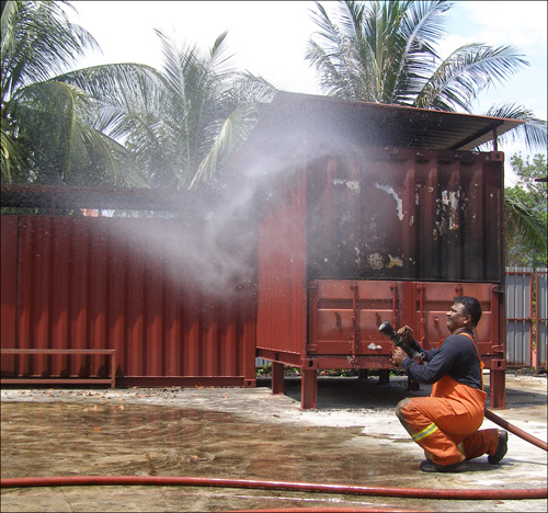
As demonstrated by Superintendent Rama Krisana Subramaniam, Bomba dan Penelamat (Fire & Rescue Malaysia) a short pulse can place a large number of small water droplets in the upper layer that develops during a compartment fire (see Figure 1).

Figure 1. Short Pulse

When presenting this concept, firefighters often present me with two questions:

  • Since water expands approximately 1700 times when turned to steam at 100o C, why doesn’t the upper layer drop down on top of the firefighters?
  • How can such a small amount of water have such a dramatic effect on the fire environment?

Math or No Math?

Using a bit of math, there is a really good explanation as to how gas cooling really works. The best answer is a bit complex, but a good conceptual explanation can be accomplished with a minimal amount of math.

Heating the water to 100o C (212o F) and production of steam transfers a tremendous amount of energy from the hot smoke and gases to the water, reducing the temperature of the hot gases. As the temperature of the hot gases is reduced so is their volume. However, don’t forget about the steam.

When water is turned to steam, it expands. At its boiling point, water vaporized into steam will expand 1700 times. A single liter of water will produce 1700 liters (1.7 m3) of steam. The expansion ratio when water is vaporized is significant. However, due to the tremendous amount of energy required to vaporize the water (and resulting reduction in gas temperature), the final volume of the mixture of hot gases and steam is less than the original volume of hot gases within the compartment.

The Key

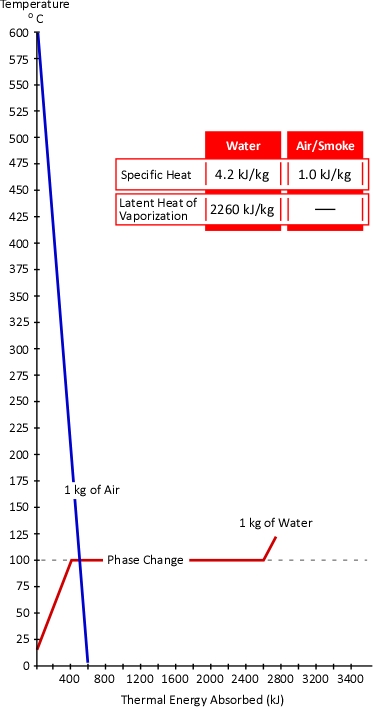
The temperature of the gases is lowered much more than the temperature of the water is increased. Why might this be the case? The key to this question lies in the concepts of specific heat and latent heat of vaporization. As illustrated in Figure 2, the specific heat of smoke is approximately 1.0 kJ/kg (Särdqvist, 2002; Yuen & Cheung, 1999) while the specific heat of water is 4.2 kJ/kg and even more importantly the latent heat of vaporization of water is 2260 kJ/kg. What this means is that it requires over four times the energy to raise the temperature of a kilogram of water by 1o C than it does to lower the temperature of smoke by the same amount. In addition, it requires 2260 times the energy to turn 1 kg of water to steam at 100o C than it does to lower the temperature of 1 kg of smoke by 1o C.

Figure 2. Heating and Cooling Curves of Smoke & Water

While water expand as it turns to steam, the hot gas layer will contract as it’s temperature drops. At the same pressure, change in the volume of a gas is directly proportional to the change in absolute temperature. If the initial temperature of the hot gas layer is 500o C (773 Kelvin) and its temperature is lowered to 100o C (373 Kelvin) the absolute temperature is reduced by slightly more than half (773 K-373 K=400 K). Correspondingly the volume of the hot gases will also be reduced by half.

An Example

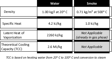
Once the underlying concept of gas cooling has been explained, the question of how a small amount of water can have such a dramatic effect may still remain. After all, the preceding explanation compared a kilogram of water to a kilogram of air. Firefighters normally do not usually think of either of these substances in terms of mass. Water is measured in liters or gallons. If measurement of smoke and air is thought of, it would likely be in cubic meters (m3) or cubic feet (ft3). Sticking with SI units, consider the properties of water and smoke as illustrated in Figure 3:

Figure 3. Properties of Water and Smoke

While over simplified, the compartment fire environment can be considered as being comprised of two zones; a hot upper layer and a cooler lower layer, each with reasonably uniform conditions (this is the approach used by computer models such as the Consolidated Model of Fire and Smoke Transport, CFAST).

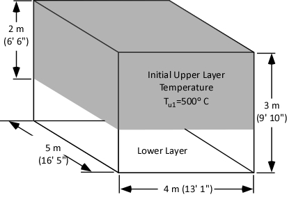
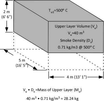
As illustrated in figure 4, our examination of gas cooling will consider a single compartment 4 meters (13’ 1”) wide and 5 meters (16’ 5”) long with a ceiling height of 3 meters (9’ 10”). The upper layer comprised of hot smoke and air is two meters deep and has an average temperature of 500o C (932o F).

Figure 4. Compartment with Two Thermal Zones

What volume of water must be applied into the upper layer to reduce its temperature from 500o C to 100o C?

Just as input of energy is required to increase temperature, energy must be transferred from a substance in order to lower its temperature. The first step in determining the water required for cooling is to calculate the energy that must be transferred from the upper layer to achieve the desired temperature reduction.

The specific heat of smoke is approximately 1.0 kJ/kg. This means that 1.0 kJ of energy must be transferred from a kilogram of smoke in order to reduce its temperature by 1o C. This requires that we determine the mass of the upper layer.

Calculation of mass involves multiplying the volume of the upper layer (40 m3) by the (physical) density of smoke (0.71 kg/m3) at the average temperature of the upper layer (500o C) as illustrated in Figure 5.

Figure 5. Mass of the Upper Layer

Specific heat is the energy required to raise the temperature of a given unit mass of a substance 1o. The same energy must be also be transferred to lower the temperature of a unit mass of a substance by 1o. As illustrated in Figure 3, the specific heat of smoke is 1.0 kJ/kg. Therefore, to lower the temperature of a single kilogram of smoke by 1o C, 1.0 kJ must be transferred from that kilogram of smoke. With an upper layer mass (Mu) of 28.24 kg, 28.24 kJ must be transferred from the upper layer to water applied for gas cooling in order to reduce its temperature by 1o C.

Reduction of upper layer temperature from 500o C to 100o C is a change of 400o. Multiplying 28.24 kJ by 400 determines the total amount of energy that must be transferred to water applied for gas cooling in order to reduce the temperature to 100o C. As illustrated in Figure 6, 11,296 kJ (11.3 MJ) must be transferred from the upper layer to the water to effect a 400o C reduction in temperature.

Figure 6. Energy Transfer Required

Now that we have determined the energy that must be transferred from the upper layer in order to lower the temperature from 500o C to 100o C, it is possible to identify how much water must be applied to accomplish this task. However, that will be the topic of my next post. In addition, I will provide an explanation as to why the volume of the upper layer does not (necessarily) increase when water applied to cool the gases turns to steam.

Ed Hartin, MS, EFO, MIFireE, CFO

References

Särdqvist, S. (2002). Water and other extinguishing agents. Karlstad, Sweden: Räddnings Verket.

Yuen, K. & Cheung, T. (1999). Calculation of smoke filling time in a fire room – a simplified approach. Journal of Building Surveying, 1(1), p. 33-37

Nozzle Evaluation

Sunday, March 28th, 2010

As with many other questions, it is likely that the answer to the question of which nozzle is best is it depends. As discussed in Effective and Efficient Fire Streams, Safe, effective and efficient fire control requires:

  • Water application to control the fire environment as well as direct attack on the fire
  • Appropriate flow rate for the tactical application (cooling hot, but unignited gases may be accomplished at a lower flow rate than direct attack on the fire)
  • Direct attack to exceed the critical flow rate based on the fires heat release rate
  • Sufficient reserve (flow rate) be available to control potential increases in heat release rate that may result from changes in ventilation
  • Water application in a form appropriate to cool its intended target (i.e., small droplets to cool hot gases or to cover hot surfaces with a thin film of water)
  • Water to reach its intended target (fog stream to place water into the hot gas layer and a straight or solid stream to pass through hot gases and flames and reach hot surfaces)
  • Control of the fire without excessive use of water

Accomplishing this requires different stream characteristics at different times. The characteristics that are optimal for gas cooling are likely quite different than for cooling hot surfaces, particularly when dealing with fully developed fire conditions in a large compartment. It is likely that direct attack on a fire with a high heat release rate in a large compartment may best be accomplished with a high flow stream having a high degree of stream cohesion and extremely large droplets. On the other hand, cooling the hot gas layer while accessing a shielded fire is most effectively and efficiently accomplished using a fog stream with a variable pattern angle, small droplet size, and a lower flow rate. No nozzle and hose system will be equally effective and efficient in all situations.

At present, there is no standardized method for testing and evaluating the effectiveness and efficiency of firefighting nozzles. However, there are a number of parameters that may be useful in the process of evaluating, selection, and specification of combination nozzles.

Application

Nozzle selection must be considered within the context of the nozzle, hose, and pump system that it will be used. If starting from scratch, it may be useful to consider each of these components. For example, high and ultra high pressure systems can provide considerably higher efficiency than low pressure systems, but they are limited to low flow rates. Low pressure systems on the other hand have larger droplet sizes and as such cannot achieve as high efficiency as higher pressure systems, but are scalable to deliver higher flow rates. If we have an existing system in place, the question may be what nozzle will provide the greatest effectiveness, efficiency, and range of capabilities.

It is also important to consider the type of buildings and occupancies in which firefighting operations will likely take place. Important factors include building and interior compartment size and occupancy. Another factor that must be considered is pressure limitations imposed by fixed fire suppression systems such as standpipes (in some cases outlet pressure is limited to 65 psi (448 kPa).

While there is no standard test methodology for determining the effectiveness and efficiency, there are a number of characteristics that can be assessed and evaluated when considering selection and specification of the handline nozzles.

Starting Point

Central Whidbey Island Fire & Rescue (CWIFR), where I serve as Fire Chief is about to start the process of evaluating nozzles for use on existing 1-3/4 (45 mm) handlines. CWIFR is a small fire district with a mix of residential and commercial occupancies located approximately 60 miles (97 km) north of Seattle, Washington. Structural fire risks are predominantly wood frame, single family dwellings with a small number of apartments, commercial buildings and institutional occupancies. The district protects an area of 50 square miles and a population of approximately 9000. Four Type I Engines and three Type I Tactical Water Tenders are staffed with a mix of full-time, part-time, and volunteer personnel operating out of four fire stations.

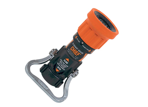
CWIFR currently uses Elkhart Chief 150 g/min (568 l/min) single flow rate nozzles that are designed to operate at a nozzle pressure of 75 psi (517 kPa) as the standard nozzle on 1-3/4 (45 mm) hoselines (similar to the nozzle shown in Figure 1, but CWIFR uses break apart nozzles with a separate tip and shutoff).

Figure 1. Elkhart Chief Nozzle

elkhart_chief

Given the same flow rate, a nozzle pressure of 75 psi provides a slight reduction in nozzle reaction in comparison with a nozzle pressure of 100 psi (about 13% when operating a straight stream). However, all things being equal, lower nozzle pressure generally results in larger droplets. Larger droplet size is not necessarily a disadvantage in direct or indirect attack, but can significantly reduce effectiveness of gas cooling. Using the current CWIFR nozzles, flow rate can be increased to approximately 180 gpm by increasing nozzle pressure to 100 psi. However, it is not possible to develop effective streams at flow rates significantly below 150 gpm as a nozzle pressure below 75 psi causes significant deterioration in stream quality, reach, and penetration.

CWIFRs nozzle tests will serve several purposes: First will be to increase members familiarity with the nozzles currently in use, their capabilities, and limitations. The second will be to evaluate other types of nozzles that may provide a broader range of capabilities and increase operational effectiveness.

Three variable flow nozzles and two automatic nozzles will be included in the initial round of testing and evaluation. All of the nozzles selected allow for development of a range of flows at a standard nozzle pressure of 100 psi.

Variable Flow Nozzles

  • Akron Turbojet
    30-60-95-125 g/min (115-230-360-475 l/min)
  • Akron Wide Range Turbojet
    Flow Range 30-95-125-150-200 g/min (115-360-475-550-750 l/min)
  • Elkhart Wide Range Phantom
    Flow Range 30-95-125-150-200 g/min (115-360-475-550-750 l/min)

Automatic Nozzles

  • Ultimatic 10-125 g/min (38-475 l/min)
  • Midmatic 70-200 g/min (265-750 l/min)

Three of these nozzles, the Wide Range Turbojet, Wide Range Phantom, and Midmatic have a higher designed flow capability than the nozzles currently used by CWIFR as well as the capability to develop effective streams at lower flow rates. Two of these nozzles, the Turbojet and Ultimatic have a lower flow capability than the nozzles currently used by CWIFR, but have been found to provide excellent gas cooling capability based on laboratory tests (Handell, 2000) and anecdotal evidence during live fire training and operational firefighting.

Basic Design

The starting point for nozzle evaluation is identification of basic characteristics:

  • Designed Nozzle Pressure
  • Flow Control: Fixed Flow, Variable Flow, Automatic
  • Flow Rates/Range

Physical & Operational Characteristics

Physical and operational characteristics can be as important as stream performance as nozzles must be used under a wide range of operational conditions.

  • Weight
  • Size
  • Size of Bail
  • Flow Control Method
  • Simplicity/Complexity of Operation

Performance Characteristics

Nozzle performance can be evaluated in a variety of different ways ranging from baseline data such as actual flow rates, range of patterns developed, and ease of operation. Other characteristics are a bit more complex such as pattern density and hang time.

  • Actual flow rate vs. specified flow rate
  • Maximum fog pattern angle
  • Reach at designed pressure and flow
  • Ease of Operation within designed pressure and flow range
  • Pattern density during continuous operation
  • Pattern density after pulsed application (2 second delay)
  • Hang time for droplets in pulsed application
  • Performance (as outlined above) outside designed pressure and flow

As identified above, performance will also be evaluated outside the designed pressure and flow range of the nozzles. For example, use of variable flow nozzles at the lowest flow setting at pressures above the designed nozzle pressure can produce extremely small droplets (more on this in a later post).

Finance and Logistical Considerations

While nozzle performance is the most important factor, it is also essential to assess the logistical and financial considerations.

  • Initial purchase price
  • Life-cycle cost
  • Maintenance requirements

Next Steps

The next post in this series will examine the nozzles currently in use by CWIFR and provide additional detail on the evaluation process.

Reference

Handell, A. (2000) Utvrdering av dimstrlrrs effektivitet vid brandgaskylning [Evaluation of the efficiency of fire fighting spray nozzles in a smoke gas cooling situation], Report 5065. Department of Fire Safety Engineering, Lund University, Sweden

Effective and Efficient Fire Streams: Part 3

Thursday, December 31st, 2009

The first two posts in this series, Effective and Efficient Fire Streams, and Effective and Efficient Fire Streams: Part 2, discussed theoretical cooling capacity, fire stream efficiency, flow rate, nozzle design characteristics and methods of use. This post drills down with a look at the relationships between the pump, hose, and nozzle in developing effective and efficient fire streams.

Where to Start?

It is likely that the most common system for developing effective and efficient fire streams involves use of combination nozzles having a designed operating pressure of approximately 100 psi (690 kPa) and what my British and Australian colleagues would refer to as layflat hose with a diameter between 1-1/2 (38 mm) and 2 (52 mm). As this type of system seems to be common to most fire services (with a few variations), this is a good place to start.

Hydraulics

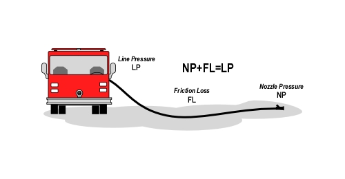
Developing effective and efficient fire streams requires an understanding of basic principles of fireground hydraulics. As discussed in earlier posts, each nozzle has a designed operating pressure. In order to provide this pressure at the nozzle, it is necessary to overcome loss of pressure in hoselines due to friction loss and increases in elevation.. Add To keep this discussion simple, the pump and nozzle will be at the same elevation.

Figure 1. Basic Handline Hydraulics

handline_line_pressure

The major factors influencing friction loss in a hoseline are flow rate and diameter of the hoseline. The Pumping Apparatus Driver/Operator Handbook (IFSTA, 2006) identifies four friction loss principles:

First Principle: All other conditions being equal, friction loss varies directly with the length of the hoseline.

Second Principle: When hoseline diameter remains constant, friction loss varies approximately with the square of the increase in flow rate. Doubling the flow increases friction loss by a factor four.

Third Principle: At the same flow rate, friction loss varies inversely as the fifth power of the diameter of the hoseline (increasing hose diameter, even a small amount has a dramatic effect on friction loss. Increasing hose diameter from 1-1/2 (38 mm) to 1-3/4 (45 mm) reduces friction loss by 46% (1.505/1.755=0.46).

Fourth Principle: If hose diameter and flow rate are held constant, friction loss is independent of pressure.

Apparatus operators must understand these basic concepts and be proficient at determining the line pressure required to develop adequate nozzle pressure to produce the necessary reach and droplet size for effective and efficient fire control operations.

Scalability

Critical and optimal flow rate are dependent on the heat release rate from the fire. The higher the heat release rate, the higher the flow rate necessary to achieve fire control. However, the flow rate required for gas cooling (unignited gas phase fuel) is not so dependent on HRR! Cooling unignited gases is most effective at a considerably lower flow rate. 30 gal/min (115 l/min) to 60 gal/min (230 l/min) is often sufficient for gas cooling (unless compartment size is extremely large).

Single flow nozzles are simple to operate as control is limited to the angle of the fog pattern and the shutoff valve. The term single flow is a bit misleading in that flow can be varied using the shutoff valve. Partially opening the shutoff valve will provide a reduced flow rate. However, partially opening the valve also provides considerably lower nozzle pressure (at the orifice), resulting in poor stream performance (limited reach and large droplet size). If a nozzle is designed to develop the low flow rate and small droplet size that is typically optimal for gas cooling, it may not have sufficient flow for direct attack on larger fires or fires in larger compartments. On the other hand, nozzle designed for higher flow rates may be ideal for direct attack on larger fires or large compartments, but are inefficient and in some cases ineffective when used for gas cooling.

Ideally, the hose and nozzle system should be scalable to provide effective and efficient operation over a fairly wide range of flow rates. At the low end, the nozzle should be capable of gas cooling at 30 gpm (115 lpm). The upper end of flow capability for direct attack has room for considerable debate.

Some agencies such as the New South Wales Fire Brigades in Australia uses the Akron Turbojet with flow settings of 30, 60, 95, & 125 gal/min (115, 230, 360, 475 l/min). On the other hand, many fire departments in the United States use nozzles having upper end flow rates of 150-200 gal/min (568-757 l/min). Having a higher flow capability provides the ability to deal with higher HRR and larger size compartments typical in contemporary residential structures and commercial buildings.

Variable flow and automatic nozzles provide the capability to vary flow rate as needed to deal with varied tactical applications and fire conditions. However, each accomplishes this task in a different manner.

Variable Flow Nozzles

When using a variable flow nozzle, the size of the nozzle orifice can be changed manually to provide several specific flow rates at the designed nozzle pressure. This requires that the apparatus operator know the flow setting of the nozzle as well as the length of line in order to determine the line pressure required to develop the correct nozzle pressure. At first glance, it appears that changing flow rates on the fly would require a great deal of radio communication between the nozzle team and apparatus operator (communication of flow setting each time it is changed). However, this challenge can easily be overcome!

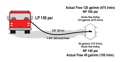
Consider what happens when the nozzle operator changes flow setting and the apparatus operator maintains the same line pressure. If the flow setting is reduced (decreasing the orifice size), flow rate will be decreased, reducing friction loss in the hoseline. As the line pressure remains the same, the pressure that is not used to overcome friction loss increases nozzle pressure. For example, if a 200 (60 m) long 1-3/4 (45 mm) hoseline equipped with a variable flow nozzle such as an Akron Turbojet is flowing 125 gal/min (475 l/min) at a nozzle pressure of 100 psi (690 kPa) and the nozzle operator changes the flow setting to 30 gal/min (115 l/min) and discharge pressure remains constant, the flow rate will be reduced to 40 gal/min (150 l/min) at a nozzle pressure of 140 psi (965 kPa) (see Figure 2).

Figure 2. Changes in Flow Rate and Nozzle Pressure

variable_flow_example

Note: The preceding example is based on tests conducted with an Akron Turbojet variable flow nozzle.

How does the reduced flow rate and increased nozzle pressure impact on fire stream effectiveness and efficiency? Increased velocity of discharge (resulting from the higher nozzle pressure) results in reduced droplet size, increasing the effectiveness and efficiency of the stream when used for gas cooling. The reduced flow rate may be insufficient for direct attack on larger fires, but the nozzle operator can quickly return to a higher flow rate by adjusting the nozzle flow control. Pumping to deliver maximum flow allows the nozzle operator to select the flow rate and nozzle pressure that is appropriate based on conditions.

Automatic Nozzles

Automatic nozzles maintain a relatively constant nozzle pressure through a given flow range. The nozzle operator controls flow using the shutoff (opening the nozzle partially provides a lower flow rate than when the nozzle is opened fully).

The shutoff valve controls both water application and flow rate, automatic nozzles are a bit simpler to use, but unlike the example provided on how to maximize the capability with the variable flow nozzle, nozzle pressure remains constant (e.g., 100 psi (690 kPa).

System Design

The starting point for designing an effective system to develop effective and efficient fire streams needs to consider the desired flow rate, typical length of hoselines required, and tactical applications. Remember there is no universal, one size fits all, answer to this question. Fire services around the world successfully use a variety of different systems. Consider the following as a starting point:

  • Both variable flow and automatic nozzles can be used effectively to apply water at varied flow rates. Automatic nozzles are simpler to operate (as they have fewer controls), but at lower flow rates are likely to develop larger droplets than variable flow nozzles operated at over 100 psi (690 kPa).
  • Hoseline diameter should be sufficient to develop the desired flow rate given the likely attack line length. Remember that as hoseline diameter increases, friction loss decreases (but so may mobility).
  • Pumping for maximum flow from the nozzle provides the nozzle operator with maximum flexibility as flow rate can be selected based on conditions. If other than maximum flow is selected as the standard flow rate it is important to train nozzle operators to request that the apparatus operator increase discharge pressure to provide maximum flow if needed.

The next post in this series will examine applications of high pressure and ultra-high pressure systems for developing effective and efficient fire streams. While considerably different than the system described in this post, this technology shows promise in expanding the range of tools available for fire control operations.

Ed Hartin, MS, EFO, MIFireE, CFO

References

International Fire Service Training Association (IFSTA). (2006). Pumping apparatus driver/operator handbook (2nd ed). Stillwater, OK: Fire Protection Publications.

Effective and Efficient Fire Streams: Part 2

Friday, December 18th, 2009

The first post in this series, Effective and Efficient Fire Streams, discussed theoretical cooling capacity, fire stream efficiency, and flow rate. This post extends the discussion, by examining how nozzle design characteristics and methods of use influence efficiency.

Think!

I do not ask that anyone believe anything that I say (or write in this blog) simply because I said so. Firefighters� opinions about nozzles are as strong as their opinions about what color fire apparatus should be painted and what type of helmet should be used to protect our heads. Each kind and type of nozzle discussed in this post is being used by firefighters all over the world to extinguish fires in buildings. This does not mean that they are all equally effective, or appropriate in all circumstances. I challenge you to think about the physics of fire control and examine your assumptions about nozzles, fire stream characteristics, and how to develop effective and efficient fire streams.

Nozzle Classification

There are several different ways to approach classification of nozzles used in structural firefighting. One simple approach is to consider the pattern or patterns in which water can be applied:

Solid Stream/Smooth Bore: This type of nozzle provides a single pattern consisting of a jet of water that maintains coherence throughout its effective reach (breaking up into extremely large droplets beyond that point)

Combination: This type of nozzle can produce a variety of patterns from a straight stream to a fog cone. Both the straight stream and fog cone are comprised of small droplets of varying diameters. Droplet diameter and consistency of droplet size is dependent on nozzle design and operating pressure (higher pressure results in smaller droplets).

Special Purpose Nozzles: In addition to solid stream and combination nozzles, there are a variety of other specialized nozzles such as piercing nozzles (fog nails), cellar nozzles (of various types), and ultra high pressure solid stream nozzles that can be used for cutting through a variety of materials as well as to produce a fog pattern with extremely small droplets. Specialized nozzles and in particular high pressure and ultra-high pressure systems will be examined in detail in a subsequent post in this series.

Nozzle Characteristics

Beyond simple classification of structural firefighting nozzles as solid stream, combination, or special purpose, nozzles may be further classified based on a number of other characteristics such as the flow rate(s) or flow range and designed operating pressure.

Single Flow: Some nozzles are designed to provide a specific, fixed flow rate at their designed operating pressure. This includes solid stream nozzles with a single sized tip and fixed flow rate combination nozzles. While these nozzles are considered to provide a single flow rate, this is not exactly true. The nozzle orifice is of fixed size, providing a given flow rate at a specified nozzle pressure. As discussed in Under Pressure, flow rate from an opening is based on the area of the opening and the velocity of the water being discharged. Increased or decreased nozzle pressure influences flow rate. For example, increasing the nozzle pressure on a solid stream nozzle from 50 psi (345 kPa) to 80 psi (352 kPa) increases flow rate by approximately 22%.

Variable Flow: Nozzles may also be designed to allow orifice size to be changed, providing variable flow rates at a given nozzle pressure. With solid stream nozzles, this is accomplished by changing the tip size. With some combination nozzles, flow and pattern vary together (e.g., the fog pattern has a lower flow rate than the straight stream setting). However, most modern combination nozzles used for structural firefighting allow adjustment of the spray pattern while maintaining flow rate. Variable flow combination nozzles may be manually adjustable with several different flow rate settings at a specified nozzle pressure.

Automatic Nozzles: Another type of nozzle that allows variation of flow rate is the automatic nozzle. With this design the nozzle adjusts flow rate by varying orifice size automatically to maintain a relatively constant nozzle pressure. With automatic nozzles the flow range specifies the lowest and highest flow rate at the designed nozzle pressure. Some automatic nozzles allow adjustment of the nozzle pressure setting to allow operation at two different nozzle pressures such as 100 psi (690 kPa) and 50 psi (345 kPa).

Nozzle Pressure: At one time the question of nozzle pressure was fairly simple, combination nozzles generally were designed to operate at 100 psi (690 kPa) nozzle pressure. However, today it is not that simple. For a variety of reasons ranging from limited pressure available from high-rise standpipe systems to the desire for lower nozzle reaction force, nozzle manufacturers are producing combination nozzles with varied designed operating pressures (commonly 50 psi (345 kPa), 75 psi (517 kPa), and 100 psi (690 kPa).

Nozzle Performance

Floyd Nelson (1989) captured the essence of nozzle performance in the following statement: �In principle, firefighting is very simple. All one needs to do is put the right amount of water in the right place and the fire is controlled� (p. 102).

Nozzles used for gas cooling must produce small droplets, be capable of varying the angle of the fog cone to have sufficient reach to cover varied sizes of compartments. Droplets with a diameter of 0.3 mm are small enough to vaporize readily in the hot gas layer, but also have sufficient mass to travel a reasonable distance (Herterich, 1960). Droplets larger than 1 mm are likely to penetrate some distance through hot gases and flames without completely vaporizing (S�rdqvist, 2001). In reality, while we know a fair bit about droplet size and performance. We don�t know much at all about the droplet sizes produced by the nozzles we are using.

What we do know is that lower pressure nozzles develop larger droplets than higher pressure nozzles of the same general design. Specific design characteristics such as the angle that the water must take as it exits the orifice and forms the fog cone also impact on droplet size. This can be illustrated using a nozzle such as the Akron Turbojet. When set on 30 gal/min (115 l/m) or 60 gal/min and operated at a nozzle pressure of 100 psi, droplet size is extremely small, providing excellent gas cooling performance. However, when flow rate is increased to 95 gal/min (360 l/min) or 125 gal/min (473 l/min) droplet size increases dramatically. While still effective for gas cooling, water application at these flow rates is less efficient.

There is no standardized test used for nozzles that determines the range of droplet sizes produced under different flow rates, nozzle pressures, cone angles, etc. However, there is light at the end of the tunnel. The technology exists to answer this interesting (and I believe important) question. Figures 1 and 2 illustrate a system comprised of lasers and a high speed camera that is used to determine droplet size from sprinkler heads. This system could also be used to assess droplet size developed by handline nozzles (if funding was available).

Figure 1. UL Sprinkler Droplet Size Test Facility

droplet_size_lab

Note: Underwriters Laboratories, Northbrook, IL

Figure 2. Laser and Camera Used for Measuring Droplet Size

droplet_laser_camera

Note: Underwriters Laboratories, Northbrook, IL

One factor that complicates things when considering droplet size and nozzle performance is that the nozzle is only one part of the equation. The nozzle operator has a significant influence on performance. For example, in a short pulse, if the nozzle is opened quickly, more of the droplets are formed with the nozzle operating at full nozzle pressure than if it is opened slowly (providing a lower pressure at the start of the pulse). The same is true if the nozzle is closed slowly rather than quickly. This is less significant with long pulses as the opening and closing phase of the pulse comprises a small percentage of the total operating time.

In direct and indirect attack, water must pass through the hot gas layer and reach burning fuel (direct attack) and/or hot surfaces (indirect attack) before significantly evaporating. If distances are not great or the temperature of the hot gas layer is not extremely high, a straight stream or narrow fog cone comprised of small droplets may be effective in accomplishing this task. When gas cooling precedes direct attack, this is often the case. However, if the distance between the nozzle and intended target is large and/or the temperature of the hot gases is high, larger droplets (or a solid stream) may be much more effective.

Selection

Many factors can (and should) be considered when selecting a system to develop effective and efficient fire streams. I used the word system intentionally as a nozzle is useless without hose, a pump, source of water, and most importantly knowledgeable and skilled firefighters to operate it.

The ideal system to develop effective and efficient fire streams for offensive firefighting would have the following capabilities (but not necessarily at the same time).

  • Can produce small droplets for gas cooling
  • Can produce larger droplets to penetrate hot gases and reach burning fuel or hot surfaces
  • Adjustable fog cone angle (allows effective reach in varied size compartments)
  • Adequate reach and stream cohesion when adjusted to straight stream
  • Ability to vary flow rate depending on fire conditions and tactical application
  • Light weight and high level of maneuverability
  • Ease of operation to simplify training requirements

At present, it is unlikely that any single system meets all of these requirements (but that is open to debate). Future posts will examine a variety of systems including those that use low, medium, high, and ultra-high nozzle pressure as well as a range of flow rates.

Ed Hartin, MS, EFO, MIFireE, CFO

References

Nelson, F. (1991). Qualitative fire behavior. Ashland, MA: International Society of Fire Service Instructors.

Herterich, O. (1960). Wasser als loschmittel [in German]. Heidelberg, Germany: Alfred Huthig

S�rdqvist, S. (2001). Water and other extinguishing agents. Karlstad, Sweden: R�ddnings Verket.

Nozzle Techniques & Hose Handling: Part 4

Thursday, December 10th, 2009

The previous posts in this series, examined the importance of proficiency in use of the firefighters primary weapon in offensive firefighting operations, and outlined several drills that can be used to develop proficiency in basic nozzle operation and hose handling.

This post extends this examination of how to develop proficiency in nozzle operation and hose handling, presenting method or developing skill in working under conditions with poor visibility and application of indirect attack as an offensive firefighting tactic.

This is my nozzle, there are many like it but this one is mine. My nozzle is my best friend. It is my life. I must master it as I master my life. Without me it is useless, without my nozzle I am useless.

I will use my nozzle effectively and efficiently to put water where it is needed. I will learn its weaknesses, its strengths, its parts, and its care. I will guard it against damage, keep it clean and ready. This I swear [adapted from the Riflemans Creed, United States Marine Corps].

Operating Without Visual Reference

Drills to this point have been under conditions of good visibility where firefighters can observe nozzle pattern and fire stream effects. However, on the fireground it is critical that these skills can be used effectively under conditions of low or no visibility.

Sometimes it is necessary to go backward in order to move forward. One way to begin the process of developing the ability to work effectively with limited visibility is to go back to Nozzle Technique and Hose Handling Drills 1 & 2 and repeat these exercises with the firefighters breathing apparatus facepieces covered (unlike working in the dark, this makes it much easier for the instructors to observe and provide feedback). While this seems like an extremely slow and incremental process, it is likely to build a higher level of skill and require less time to develop proficiency than simply fumbling about in the dark!

Door Entry and Gas Cooling

In Nozzle Technique and Hose Handling: Part 3, door entry was illustrated at an exterior door. However, this method should be used anytime that firefighters encounter a closed door that may have hot gases or fire behind it. This becomes even more important when operating in a smoke (fuel) filled environment.

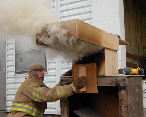
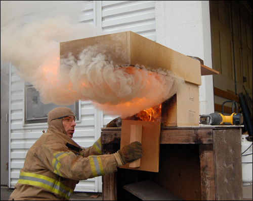
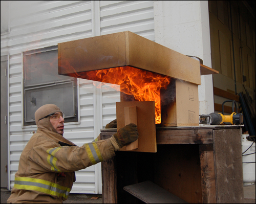
Smoke is fuel! The upper (hot gas) layer may contain a substantial mass of fuel that is ready to ignite. Flames exiting from a compartment door can ignite this fuel, resulting in rapid fire progression through the upper layer and into adjacent compartments. This phenomenon is demonstrated by CFBT-US Senior Instructor Trainer Matt Leech (LT Tualatin Valley Fire & Rescue) in Figures 1 through 3. While this demonstration involves use of a single compartment dolls house and porch roof, the same phenomena can occur on a larger scale in any type of structure.

Figure 1. Accumulation of Fuel Overhead

dolls_house_pr_1

Figure 2. Extension of Flames and Ignition of Fuel Overhead

dolls_house_pr_2

Figure 3. Transition to Flaming Combustion Overhead

dolls_house_pr_3

This simple demonstration illustrates the hazards presented by smoke overhead, the importance of gas cooling, and good door entry technique. While often overlooked, recognition of this hazard is not new. Smoke contains unburned fuel and when mixed with air in the proper proportion becomes a flammable mixture (Layman, 1955).

When working under conditions of limited visibility, other sensory feedback becomes even more important to the nozzle operator. It is essential that firefighters become familiar with audible indicators of stream performance. Think about the sound of a straight stream hitting the ceiling or a wall versus the sound of a fog pattern applied into the hot gas layer (without significant contact with compartment linings). Would you be attuned to the difference in sound? This is important when you cant see the pattern being discharged. Changes in temperature can also be an important indicator. However, it is important to remember that perceived temperature is also influenced by moisture. Excess steam production (from water hitting hot compartment linings) may make it seem like the temperature is rising, when this is due to increased moisture content in the smoke and air. If it seems like it is getting hotter, it is important to recognize if this is due to worsening fire conditions, or inappropriate water application.

Drill 6-Operating Without Visual Reference: This drill integrates door entry, hose handling, and nozzle techniques (pulsing and painting) under conditions with limited visibility. The drill can be conducted with the facepiece covered, in darkness, or using cold smoke (e.g., from a smoke machine). Learners should begin by using good door entry technique on an exterior door and then move through several compartments (preferably of different sizes), encountering several doors (some of which should be closed) along the way to the seat of the fire. Alternately, this drill can be used to practice hose handling and nozzle technique in the context of primary search with a hoseline (or in support of crews performing search).

Hose Handling & Nozzle Technique Drill 6 Instructional Plan

Indirect Attack

Indirect attack is a commonly misunderstood firefighting tactic. Common misconceptions include:

  • Indirect attack is only performed from the exterior of the building.
  • Indirect attack will push fire throughout the building.
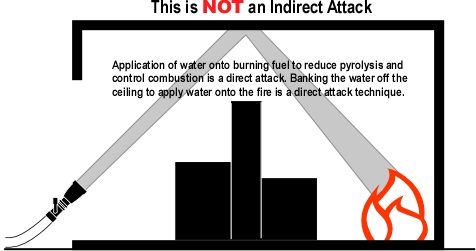
  • Indirect attack involves banking water off the ceiling to reach burning fuel that is inaccessible to direct application of water (see Figure 4).
  • Indirect attack and gas cooling is the same thing.

These statements are absolutely incorrect!

Figure 4. What Indirect Attack is NOT.

bank_shot

Several years ago I had a company officer that I worked with tell me that he had learned about a new fire control technique called the indirect attack at strategies and tactics class. I loaned him a small blue book titled Attacking and Extinguishing Interior Fires (Layman, 1955) and observed that this was not exactly a new idea.

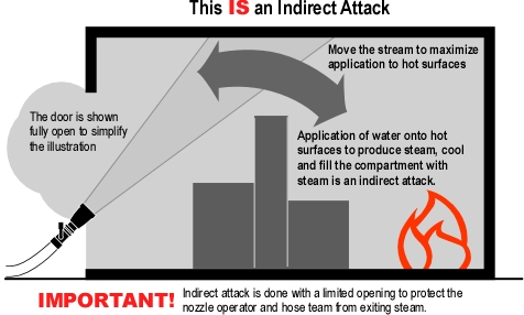
The concept of the indirect attack was an outgrowth of extensive study of fuel oil fires within confined spaces conducted by the instructor staff of the US Coast Guard Firefighting School at Fort McHenry in Baltimore, Maryland during World War II (Layman, 1955). The term indirect, referred to application of water into a hot compartment, but not directly onto the burning fuel. Conversion of water to steam absorbed a tremendous amount of energy and the expansion of steam filled the compartment (and potentially adjacent compartments which may also have been involved in fire).

In 1947, Lloyd Layman completed his service with the US Coast Guard and returned to duty as Fire Chief with the Parkersburg West Virginia Fire Department. Over the next two years, Layman and the members of his department worked to implement the concept of indirect attack for structural firefighting. In 1950 Chief Layman delivered a presentation titled Little Drops of Water (Layman, 1950) which outlined the adaptation of indirect attack for structural firefighting. In 1952 he completed Attacking and Extinguishing Interior Fires (Layman, 1955), a textbook that provided a more comprehensive look at indirect attack including several case studies based on incidents in Parkersburg where this approach had been used successfully in dealing with both residential and commercial fires.

As presented by Layman, the indirect attack was generally performed from the exterior of the building. However, it is important to recognize historical context. In the late 1940s respiratory protection (when it was used) was often limited to All Service Masks, which used a filter mechanism to remove toxic products of combustion (to some extent), but could not be used in significantly oxygen deficient atmospheres.

Laymans Error: Chief Layman made a number of extremely important and astute observations, particularly with regards to the tremendous cooling capacity of water when it is not only heated to its boiling point, but also converted to steam. However, one of the major assumptions related to indirect attack was in error. Layman states: The injection of water into a highly heated atmosphere results in rapid generation of steam[increasing] the atmospheric pressure within the space (p. 36-37). This points to the Chiefs assumption that steam produced as water was evaporated in the hot gas layer added to the total volume of gas and vapor within the space (i.e., the volume of steam was added to the volume of smoke and hot gases in the compartment). As discussed in Estimating Required Fire Flow: The Iowa Formula [LINK]; this is incorrect, water vaporized as it passes through the hot gas layer actually reduces total volume (due to cooling of the hot gases). On the other hand, water that is vaporized in contact with hot surfaces (that did not significantly cool the gases as it passed through the hot gas layer) adds to total volume as expanding steam is added to the volume of hot gases within the compartment. The difference between indirect attack and gas cooling will be explored in detail in my next post on Fire Stream Effectiveness and Efficiency.

Figure 5. Indirect Attack

indirect_attack

Drill 7-Indirect Attack from the Door: When faced with a fully developed fire in an enclosed area or a severely ventilation controlled fire (decay phase) that presents potential for a ventilation induced flashover or backdraft. Indirect attack may be an effective option for fire control. However, this tactic is not limited to exterior operations. Indirect attack can be initiated as part of the door entry procedure (exterior or interior doorway). If dynamic risk assessment indicates that entry is not viable due to fire conditions, the nozzle operator can use long pulses from the doorway (while the other member of the hose team controls the door) to apply water to hot surfaces, producing steam to gain control of conditions within the compartment prior to entry. This fire control method should be integrated with effective tactical ventilation (think planned, systematic, and coordinated).

Hose Handling & Nozzle Technique Drill 7 Instructional Plan

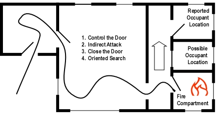
This approach can be extremely useful when the door to the fire compartment can be controlled and the hose team is presented with multiple priorities (persons reported and the need to control the fire to maintain the safety of interior operations). Figure 6 illustrates an example of how an indirect attack may be used when operating from the interior. In this scenario, the first arriving engine observes a fully developed fire in the bedroom on the A/D corner of a single family dwelling and receives information that an occupant is in the bedroom on the C/D corner. Rapidly developing fire conditions require immediate fire control. The crew makes entry from Side A, cools the hot gases overhead as they proceed to the fire compartment. As it is necessary to control the fire before proceeding past the involved compartment, they control the door, implement an indirect attack, and then extend an oriented search to locate the occupant while the nozzle operator protects the means of egress and maintains orientation for the firefighter performing the search in the adjacent compartments.

Figure 6. Application of Interior Indirect Attack.

indirect_bedroom_fire

While there are other tactical approaches that could be taken in this situation, use of an indirect attack allows the hose team to address both life safety (firefighters and occupants) and fire control tactical priorities.

Master Your Craft

Ed Hartin, MS, EFO, MIFIreE, CFO

References

Layman, L. (1955). Attacking and extinguishing interior fires. Boston, MA: National Fire Protection Association.

Layman, L. (1950). Little drops of water. Unpublished paper, presented at the Fire Department Instructors Conference (FDIC), Memphis, TN.

Effective and Efficient Fire Streams

Thursday, November 26th, 2009

It is often stated and commonly believed that it takes gpm to overcome Btu. While I suspect that firefighters understand the underlying intent of this statement, it is actually incorrect as it is comparing apples and oranges. Flow rate is expressed in terms of volume and time (gal/m or l/m). However, Btu (or Joules) is a measure of quantity (more like volume than flow rate).

You can say that it takes gallons (or liters) to overcome Btu (or Joules), But the rate at which energy is absorbed by a fire stream must overcome heat release rate (energy released/unit of time). This concept points to the need for a higher flow rate when the heat release rate from a fire is larger. This leads to another common fire service saying: Big Fire, Big Water. While this is not completely incorrect, it is a bit misleading as it does not account for the efficiency of the fire stream in absorbing energy. Not all of the water that leaves the nozzle absorbs the same amount of energy.

Theoretical Cooling Capacity

Water is an excellent extinguishing agent because it has a high specific heat (energy required to raise its temperature) and high latent heat of vaporization (energy required to change it from water to steam). As illustrated in Figure 1, conversion of water to steam is most significant as it absorbs 7.5 times more energy than heating water from 20o C (68o F) to its boiling point.

Figure 1. Theoretical Cooling Capacity

theoretical_cooling_capacity

However, this only tells us the theoretical cooling capacity of a single kilogram of water at 20o C (68o F) if it is raised to 100o C (212o F) and completely vaporized. Examining theoretical cooling capacity in terms of flow rate requires a bit more work.

Flow is defined in terms of gallons per minute (gal/m) or liters per minute (l/m) and theoretical cooling capacity of water was defined in terms of energy absorbed per second per unit mass (MJ/kg) we need to work through conversion to common units of measure.

While SI units are simpler to work with, I have worked cooling capacity out in both liters per minute (LPM) and gallons per minute (GPM). However, in that specific heat and latent heat of vaporization are applied to mass rather than volume and Watts are joules per second, it is first necessary to covert flow rate into kg/s

Figure 2. Flow Rate and Theoretical Cooling Capacity

100_lpm_100_gpm

This example assumes instantaneous heat transfer and 100% efficiency in conversion of water to the gas phase. Neither of which is possible in the real world!

Factors influencing effectiveness and efficiency of heat transfer (Svennson, 2002) include:

  • Diameter (in the gas layer and on surfaces)
  • Temperature (in the gas layer and on surfaces)
  • Velocity (in the gas layer)
  • Film formation (on surfaces)
  • Temperature of the gas layer
  • Surface temperature

Fire Stream Efficiency

The firefighters power is not simply related to flow rate, but flow rate effectively applied to transfer heat from hot gases and surfaces by changing its phase from liquid (water) to gas (steam). Extinguishing a compartment fire generally involves converting a sufficient flow (gal/m or l/m) of water to steam. So while the steam itself does not generally extinguish the fire, the energy absorbed in turning the water to steam has the greatest impact on fire extinguishment.

Experimental data (Hadjisophocleous & Richardson, 2005; Srdqvist, S., 1996) has shown that the cooling efficiency of water in both laboratory experiments and actual firefighting operations ranges from 0.2 to 0.6. Srdqvist (1996) suggests that an efficiency factor of 0.2 be used for interior fog nozzles. Based on my personal observations (but no experimental data), I think that Srdqvists efficiency factor of 0.2 might be just a bit on the low side. Barnett (as cited in Grimwood,2005) suggests that an efficiency factor of 0.5 be used for solid or straight stream application and 0.75 for fog application. The following table takes a slightly more conservative approach, using 0.6 as an average efficiency factor.

Figure 3. Flow Rate and Adjusted Cooling Capacity

adjusted_cooling_capacity

Figure 3 is provided to illustrate the impact of efficiency (or lack thereof) on fire stream cooling capability. The key point is that actual cooling capability is considerably less than the theoretical cooling capacity. Another complication is that in addition to nozzle performance characteristics, nozzle efficiency is also dependent on the skill of the nozzle operator, the manner in which water is applied (straight stream, narrow fog pattern, wide fog pattern), the configuration of the space, and fire conditions. Unfortunately, there is no standardized test with specified conditions that permits comparison of different nozzles and/or methods.

However, the concept of efficiency gives rise to an interesting question. Does a nozzle flowing 100 gpm with an efficiency factor of 0.6 have the same extinguishing capability as 200 gpm nozzle with an efficiency factor of 0.3. This is simple math! The cooling capacity would be identical. While the practical application is more complex (as we do not really know the efficiency factors for the two nozzles and manner in which they are being used), this is worth thinking about.

Flow Rate or Heat Absorption Capacity

CFBT-US Senior Instructor Trainer Matt Leech (LT Tualatin Valley Fire & Rescue) proposed (half in jest) that nozzles should be labeled with their potential cooling capacity rather than flow rate. While this idea did not get significant traction, it is important for firefighters to recognize that flow rate and fire stream characteristics have a significant impact on potential cooling capacity.

Fire Stream Effectiveness

Safe, effective and efficient fire control requires:

  • Water application to control the fire environment as well as direct attack on the fire
  • Appropriate flow rate for the tactical application (cooling hot, but unignited gases may be accomplished at a lower flow rate than direct attack on the fire)
  • Direct attack to exceed the critical flow rate based on the fire’s heat release rate
  • Sufficient reserve (flow rate) be available to control potential increases in heat release rate that may result from changes in ventilation
  • Water application in a form appropriate to cool its intended target (i.e., small droplets to cool hot gases or to cover hot surfaces with a thin film of water)
  • Water to reach its intended target (fog stream to place water into the hot gas layer and a straight or solid stream to pass through hot gases and flames and reach hot surfaces)
  • Control of the fire without excessive use of water

Accomplishing this requires different stream characteristics at different times. The characteristics that are optimal for gas cooling are likely quite different than for cooling hot surfaces, particularly when dealing with fully developed fire conditions in a large compartment.

Priorities

As regular readers have likely noted my posting schedule has been a bit off of late. My responsibilities as the new Fire Chief with Central Whidbey Island Fire & Rescue preclude the necessary research and writing necessary to constantly post twice weekly. I will be scaling back to a single post on Thursday for the next few months while I get a handle on my new job and get my family moved to Whidbey Island.

Ed Hartin, MS, EFO, MIFIreE, CFO

References

Grimwood, P. (2005) Firefighting Flow Rate: Barnett (NZ) Grimwood (UK) Formulae. Retrieved January 26, 2008 from http://www.fire-flows.com/FLOW-RATE%20202004.pdf

Hadjisophocleous, G.V. & Richardson, J.K. (2005). Water flow demands for firefighting. Fire Technology 41, p. 173-191.

Srdqvist, S. (1996) An Engineering Approach To Fire-Fighting Tactics Sweden, Lund University, Department of Fire Safety Engineering

Svennson, S. (2002). The operational problem of fire control (Report LUTVDG/TVBB-1025-SE). Sweden, Lund University, Department of Fire Safety Engineering.

Nozzle Techniques & Hose Handling: Part 3

Thursday, November 19th, 2009

The previous posts in this series, examined the importance of proficiency in use of the firefighters’ primary weapon in offensive firefighting operations, and outlined several drills that can be used to develop proficiency in basic nozzle operation and hose handling.

Developing proficiency in nozzle use is somewhat like building skill with a rifle. Understanding what end of the rifle the bullet comes out of and that the rifle is fired by pulling the trigger is the easy part, learning to consistently hit what you are aiming at over varied distances requires considerably more effort.

This is my nozzle, there are many like it but this one is mine. My nozzle is my best friend. It is my life. I must master it as I master my life. Without me it is useless, without my nozzle I am useless.

I will use my nozzle effectively and efficiently to put water where it is needed. I will learn its weaknesses, its strengths, its parts, and its care. I will guard it against damage, keep it clean and ready. This I swear [adapted from the Rifleman’s Creed, United States Marine Corps].

In the first three nozzle drills learners develop basic proficiency in basic nozzle use (fixed position), integrating nozzle use while moving a hoseline forward and back, and use of the nozzle while moving the hoseline through varied size compartments. This post will provide an overview of door entry procedures.

Door Entry Concepts

For many firefighters, door entry is simply a process of remembering to “try before you pry” and then figuring out how to force the door if it is locked. For others it is simply kicking the door in! Often overlooked is the fact that the entry point is a ventilation opening; sometimes an inlet, sometimes an outlet, and often both. When the fire is ventilation controlled, opening the door and increasing air flow to the fire will result in increased heat release rate. Depending on the stage of fire development and conditions within the compartment or structure, this may result in extreme fire behavior such as a ventilation induced flashover or backdraft (see Fuel & Ventilation).

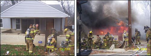
As illustrated in Figure 1, firefighters often encounter rapidly changing conditions after making entry. In this incident, flashover occurred less than 60 seconds after firefighters opened the door and made entry (see Situational Awareness is Critical for additional information on this incident)

Figure 1. Rapidly Changing Conditions

pg_before_after

Note: Photos by Probationary Firefighter Tony George, Prince Georges County Fire Department.

Safe and effective firefighting operations depend on effectively reading the fire and recognizing potential stages of fire development and burning regime (see previous posts on Reading the Fire) and effective tactical operations to take control of the fire environment. Door entry is an important element in this process.

Door Entry Procedure

As you review this door entry procedure, you may find that it makes sense to you exactly as presented. On the other hand, you may find that some elements (e.g., size-up and dynamic risk assessment) make sense, but other components (e.g., cooling overhead prior to opening the door) require a bit more of a leap. The elements of the door entry process reinforce one another, adopt the elements that make sense to you, but consider the value of the procedure as an integrated process. The process outlined is not followed in a lock-step manner, it is important for the hose team to take action based on observed conditions.

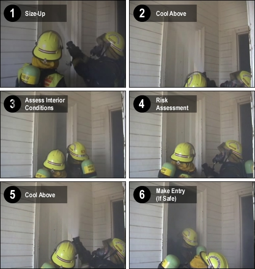
Size-Up: Door entry begins with a focused size-up as you approach the building. Assessment of conditions is not only the incident commander or officer’s job. Each member entering the building should perform a personal size-up and predict likely conditions. When making entry, size-up becomes more closely focused on conditions observed at or near the door and includes an assessment of potential forcible entry requirements as well as B-SAHF (Building-Smoke, Air Track, Heat, and Flame) indicators. If available, a thermal imaging camera (TIC) can be useful, but remember that temperature conditions may be masked by the thermal characteristics of the building. If a thermal imaging camera is not available, application of a small amount of water to the door may indicate temperature and the level of the hot gas layer (water will vaporize on contact with a hot door).

Size-up begins as you exit the apparatus and approach the building, but continues at the door and after you make entry!

At the door, pay close attention to air track and heat (door temperature) indicators as these can provide important clues to conditions immediately inside the building!

Control the Door: If the door is open, close it. If it is closed, don’t open it until you are ready. Heat release requires oxygen, controlling the air supply to the fire controls heat release rate. If you force the door in preparation for making entry, make sure you maintain control of it.

Gas Cool Above the Door and Assess, and Control Interior Conditions: When you open the door to assess conditions inside, hot smoke will likely exit at the top of the door. If it is hot enough it may auto-ignite. The hazard presented by the exiting smoke can be reduced by applying two short pulses above the door just as it is opened (the firefighter controlling the door should crack the door as the first pulse is applied).

The door should be opened sufficiently to allow the nozzle operator to visualize interior conditions, but not so much that a large amount of air is introduced (no magic number on how far to open, “it depends”). If hot smoke is present, the nozzle operator should cool the gases inside the compartment from the doorway. This may involve a short pulse or two or it may involve a longer pulse, depending on the size of the compartment and conditions (again, this requires the nozzle operator to think!).

Close the Door: While there is often a sense of urgency to make entry (due to developing fire conditions, persons reported, etc.), this step is important as it provides an opportunity for a focused risk assessment.

Risk Assessment: Is it safe to make entry (or to make entry through this opening)? Fully developed fire conditions inside the door or a pulsing air track (indicating potential for vent induced flashover or backdraft) may indicate a need to consider alternative tactics).

Entry: If it is safe to make entry, the process of cooling above the door as it is opened is repeated and hot gases inside the compartment are cooled as the hose team makes entry.

Figure 2. Door Entry Procedure

door_entry_multi-panel

Note: Adapted from video clip 00000010 on the 3D Firefighting: Training, Techniques and Tactics Resource DVD.

Remember: The purpose of door entry procedures is to reduce risk of extreme fire behavior during and immediately after entry! Door entry procedures should be used any time that hot smoke or flames may be on the other side of the door. These procedures are used at exterior doors when making entry and on closed doors encountered inside the building.

Drill 4-Door Entry-Inward Opening Doors: Many doors (particularly interior and exterior residential) open inward (away from the nozzle team), door entry requires that the hose team integrate forcible entry, door control, and nozzle operation. Practicing door entry procedures with a variety of inward opening door configurations (location of the door in relation to walls and with varied size compartments) is critical in developing proficiency.

Drill 5-Door Entry-Outward Opening Doors: Commercial doors (and some interior doors) will open outward (towards the hose team). Outward opening doors require a somewhat different position when performing door entry. Firefighters must develop skill in performing door entry with both inward and outward opening doors.

Hose Handling & Nozzle Technique Drill 4 & 5 Instructional Plan

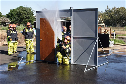
These two drills can be conducted using any door where water can be applied. However, a free-standing door entry prop (see Figure 3) provides a simple and effective aid to developing door entry proficiency.

Figure 3. Door Entry Prop

door_entry_prop

Note: Photo by Inspector John McDonough, ASFM, New South Wales Fire Brigades.

Alternately, a forcible entry prop could be used to integrate the forcible entry component of the door entry process.

Drills

As discussed in Nozzle Techniques and Hose Handling: Part 2 [LINK], it is essential for firefighters to have the ability to react immediately to deteriorating conditions. While battle drills will be discussed in depth in a subsequent post, consider how this concept might apply during door entry. What action should the hose team take if they encounter strong indicators of backdraft conditions at the doorway (e.g. pulsing air track, thick (optically dense) smoke)? How should the hose team react if, despite following good practice, conditions worsen immediately after entry?

Ed Hartin, MS, EFO, MIFireE, CFO

References

Grimwood, P., Hartin, E. McDonough, J. & Raffel, S. (2005). 3D firefighting: Training, techniques, and tactics. Stillwater, OK: Fire Protection Publications.

Under Pressure

Tuesday, November 17th, 2009

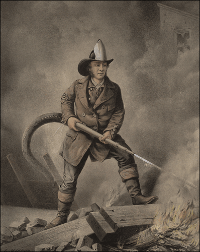
Understanding how to develop fire streams has been critical since firefighters began to use hose and nozzles (Figure 1) to increase the effectiveness and efficiency of firefighting operations.

Figure 1. In the Beginning!

fireman

When selecting handline nozzles, firefighters and fire officers generally consider four nozzle characteristics: 1) type of nozzle (combination or solid stream/smoothbore), 2) fixed or variable flow, 3) flow rate, and 4) designed operating pressure. Saving the big debate regarding combination and solid stream/smoothbore nozzles for another post, this post will focus primarily on nozzle pressure and flow rate.

Nozzle Function

A little over 20 years ago I was asked an interesting question by a newly hired recruit firefighter. She had no prior fire service experience and was puzzled by the hose evolutions being taught during her academy. As I attempted to help her make sense of these alien concepts, she finally asked Whats the pump for? Why dont we just put the nozzle on the end of the hose from the hydrant? Her instructors may have assumed that hydraulics was a topic for apparatus operators or that everyone understood the basic concepts involved in developing an effective fire stream.

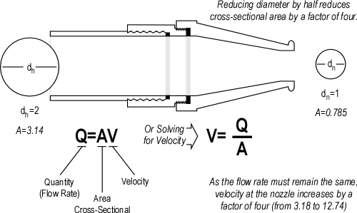
The primary function of a nozzle is to increase the velocity of water flowing from the hoseline. A fire stream must have sufficient velocity for water to reach from the nozzle to the intended target. The simple equation illustrated in Figure 2 is essential to understanding nozzle design and performance. Flow rate (the quantity of water) from a nozzle is dependent on the area of the opening and the velocity of the water being discharged (for a given size opening, the greater the velocity the higher the flow rate).

Figure 2. Important Equation

qav_nozzle_purpose

As indicated in the equation Q=AV, flow rate is related to velocity and the size (area) of the nozzle orifice. This relationship is simple to understand when looking at solid stream/smoothbore nozzles. Nozzle pressure translates to velocity at the tip. For a given size tip, increasing nozzle pressure increases velocity and thus the flow rate from the tip. For example, a 1-1/4 (32 mm) tip will flow 317 gpm (1200 lpm) at 50 psi (345 kPa). Increasing the nozzle pressure to 80 psi (552 kPa) increases the flow rate to 401 gpm (1518 lpm). Flow rate can be varied by changing the size of the tip, the nozzle pressure, or both.

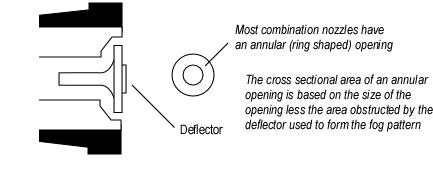
Visualizing nozzle orifice size is a bit more difficult with combination nozzles. Most combination nozzles use a deflection stem (see Figure 3) to form the fog pattern. The nozzle orifice is an annular (ring shaped) space between the deflector and the body of the nozzle tip.

Figure 3. Combination Nozzle Orifice

combination_nozzle_orifice

The change in direction at the deflection plate results in formation of small droplets of water. Nozzles may also have fixed teeth or a spinning, toothed turbine to aid in the production of appropriate sized droplets as water leaves the nozzle.

Nozzle Pressure and Droplet Size

Water is an excellent extinguishing agent because it has a high specific heat (energy required to raise its temperature) and high latent heat of vaporization (energy required to change it from water to steam). Of these two factors, conversion of water to steam is most significant as it absorbs 7.5 times more energy than heating water from 20o C (68o) to its boiling point. The firefighters power is not simply related to flow rate, but flow rate effectively applied to transfer heat from hot gases and surfaces by changing its phase from liquid (water) to gas (steam). Extinguishing a compartment fire generally involves converting a sufficient flow (gpm or lpm) of water to steam. So while the steam itself does not generally extinguish the fire, the energy absorbed in turning the water to steam has the greatest impact on fire extinguishment

Where the water is vaporized into steam depends on the method of fire control being used (direct attack, indirect attack, or 3D gas cooling). In direct attack water is vaporized on burning and pyrolyzing fuel surfaces to slow and stop the process of pyrolysis. Water is also vaporized on contact with hot surfaces in an indirect attack, but in this case the purpose is to produce a sufficient volume of steam to fill the compartment, achieving fire control or mitigating potential for extreme fire behavior such as a backdraft. Gas cooling on the other hand requires that the majority of the water be vaporized in the hot gas layer. This cools the hot gases (fuel) overhead, providing buffer zone and safer work environment for firefighters. It is important to remember that gas cooling is not an extinguishing technique, but merely one tool in controlling the fire environment.

Heat moves from objects of higher temperature to objects of lower temperature until temperature equalizes. Key factors in the speed of heat transfer are the difference in temperature and surface area of the materials. In the fire environment, burning fuel, nearby surfaces, and hot gases are considerably higher temperature than the water used for fire control and extinguishment. Surface area of the water in contact with the material being cooled is extremely significant in determining the speed of heat transfer. A larger surface area in relation to the amount of water will result in faster heat transfer and more rapid cooling.

If the volume of water remains the same, reducing droplet size increases surface area substantially. For example if droplet size is reduced by half, surface area increases by a factor of four (see Figure 4).

Figure 4. Droplet Diameter and Surface Area

surface_area_sphere

Note. Adapted from Water and Other Extinguishing Agents (p. 194) by Stefan Srdqvist, 2002, Karlstad, Sweden: Raddningsverket. Copyright 2002 by Stefan Srdqvist and the Swedish Rescue Services Agency

Increased surface area increases heat transfer as droplets travel through the hot gas layer, rapidly reducing temperature. However, the down side of smaller droplets is that they do not travel as far and may not be able to penetrate a large distance in an extremely hot environment, making a fog pattern with small droplets potentially less effective in direct attack or when working in an extremely large compartment. Fortunately, when a fog pattern is adjusted to a straight stream much (but not necessarily all) of this problem is overcome.

What does nozzle pressure have to do with droplet size? Nozzles do not produce uniform droplet sizes. The fog pattern developed by a typical combination nozzle produces a mix of small and larger droplets. However, average droplet size and the percentage of droplets that are 0.3 mm (0.012) in diameter is dependent on both nozzle design and pressure. However, for any nozzle design, increased nozzle pressure will result in smaller droplets.

Gresham Fire & Emergency Services conducted a series of qualitative tests on droplet size produced by the Task Force Tips Dual-Pressure Mid-Force Nozzle operating at 50 psi (345 kPa) and 100 psi (689 kPa). Droplet size was assessed by examining hang time, the time which droplets remained suspended in the air after a short pulse of water fog (smaller droplets remain suspended for a longer time while large droplets fall to the ground more quickly). Results of this test were captured on video and synched to ensure that the visual comparison was at the same time after the nozzle was closed. As illustrated in Figure 5, with the same flow rate, the nozzle pressure of 50 psi (345 kPa) resulted in larger droplets than a nozzle pressure of 100 psi (689 kPa).

Figure 5.

High and Low Nozzle Pressure Test

Nozzles operating at a lower pressure will have larger droplet size. This does not impact substantially on direct attack, but can have a significant impact on the effectiveness and efficiency of these nozzles when used for gas cooling. This does not mean that they cannot be used! It simply means that they will be less effective and are likely to result in less efficient vaporization of water (more water will end up on the floor).

Impact on Operations

While it is important to understand the underlying principles related to nozzle design and performance, it is even more important to understand the impact of these concepts on firefighting operations. The next post in this series will examine the concepts of efficiency and effectiveness in greater depth and why effective cooling capacity may be more important than simply looking at flow rate.

Ed Hartin, MS, EFO, MIFireE, CFO

References

Srdqvist, S. (2002). Water and other extinguishing agents. Karlstad, Sweden: Raddningsverket (Swedish Rescue Services Agency).

Reading the Fire 6

Thursday, April 16th, 2009

Application of the B-SAHF (Building, Smoke, Air Track, Heat, & Flame) organizing scheme for critical fire behavior indicators to photographs or video of structure fires provides an excellent opportunity to develop your knowledge of fire behavior and skill in reading the fire.

This video clip was recommended by Captain Virgil Hall, Tualatin Valley Fire & Rescue. Virgil is stationed at Station 64 and is one of TVF&R’s CFBT Instructors.

Residential Fire

Download and print the B-SAHF Worksheet. Consider the information provided in the short video clip. First, describe what you observe in terms of the Building, Smoke, Air Track, Heat, and Flame Indicators and then answer the following five standard questions?

  1. What additional information would you like to have? How could you obtain it?
  2. What stage(s) of development is the fire likely to be in (incipient, growth, fully developed, or decay)?
  3. What burning regime is the fire in (fuel controlled or ventilation controlled)?
  4. What conditions would you expect to find inside this building?
  5. How would you expect the fire to develop over the next two to three minutes?

Review the video again, watch the indicators on Side A closely, and give some thought to the following questions posed by Captain Hall:

  1. How did the smoke and flame indicators change?
  2. What did this indicate?
  3. Why did these changes occur (what were the influencing factors)?

Special thanks to Captain Hall for recommending this video clip. Please feel free to contribute to this process and share or recommend video clips or photographs that will help us develop our skill in reading the fire.

Master Your Craft

Remember the Past

While some firefighters have heard about the incidents involving multiple fatalities, others have not and most do not know the stories of firefighters who died alone. In an effort to encourage us to remember the lessons of the past and continue our study of fire behavior, I will occasionally be including brief narratives and links to NIOSH Death in the Line of Duty reports and other documentation in my posts. The first narrative in this post is incomplete as this incident, resulting in the death of two members of the Houston Fire Department occured last Sunday. It is important for us to continue our efforts to understand and mitigate the complex and interrelated factors that result in firefighter fatalities occuring during structural firefighting operations.

April 12, 2009
Captain James Harlow
Firefighter Damion Hobbs

Houston Fire Department, Texas

Captain James Harlow and Firefighter Damion Hobbs of the Houston, Texas Fire Department lost their lives in the line of duty while conducting primary search in a single family dwelling on the morning of April 12, 2009. Preliminary information indicates that Captain Harlow and Firefighter Hobbs were trapped by rapid fire progress, possibly influenced by wind. The Houston Fire Department, Texas State Fire Marshal, and National Institute for Occupational Safety and Health (NIOSH) are all investigating this incident. More information will be posted as it becomes available.

April 11, 1994
Lieutenant Michael Mathis
Private William Bridges
Memphis Fire Department, Tennessee

On April 11, Lt. Michael Mathis and Private William Bridges of the Memphis (TN) Fire Department were killed when they became trapped and overcome by smoke during a fire on the ninth floor of a high rise building. Two civilians also died in the arson fire. Lt. Mathis became disoriented when he was caught in rapidly spreading fire conditions on the fire floor, burning him and causing his SCBA to malfunction. He found his way into a room on the ninth floor were he was later discovered by other fire crews with his SCBA air depleted. Private Bridges, aware that Lt. Mathis was unaccounted for after several unsuccessful attempts to contact him by radio, left a safe stairwell where he had been attempting to fix a problem with his own SCBA. Investigators believe Bridges was trying to locate Lt. Mathis. Bridges became entangled in fallen cable TV wiring within a few feet of the stairwell, and died of smoke inhalation after depleting his SCBA supply. A Memphis Fire Department investigation found many violations of standard operating procedures by companies on the scene, including crews taking the elevator to the fire floor, problems with the incident command system and coordination of companies, operating a ladder pipe with crews still on the fire floor, and a failure of personnel, including Lt. Mathis and Private Bridges, to activate their PASS devices.

April 16, 2007
Firefighter-Technician I Kyle Robert Wilson
Prince William County Department of Fire and Rescue, Virginia

Technician Wilson was assigned to Tower 512, a ladder company. Tower 512 was dispatched to a reported house fire at 0603 hours. The Prince William County area was under a high wind advisory as a nor’easter moved through the area. Sustained winds of 25 miles per hour with gusts up to 48 miles per hour were prevalent in the area at the time of the fire dispatch.

Initial arriving units reported heavy fire on the exterior of two sides of the single-family house, and crews suspected that the occupants were still inside the house sleeping because of the early morning hour. A search of the upstairs bedroom was conducted by Technician Wilson and his officer. A rapid and catastrophic change of fire and smoke conditions occurred in the interior of the house within minutes of Tower 512’s crew entering the structure. Technician Wilson became trapped and was unable to locate an immediate exit. “Mayday” radio transmissions of the life-threatening situation were made by crews and by Technician Wilson. Valiant and repeated rescue attempts to locate and remove Technician Wilson were made by the firefighting crews during extreme fire, heat, and smoke conditions. Firefighters were forced from the structure as the house began to collapse on them and fire conditions worsened. Technician Wilson succumbed to the fire and the cause of death was reported by the medical examiner to be thermal and inhalation injuries.

An extensive report on this incident is available from the Prince William Department of Fire and Rescue: Technician Kyle Wilson LODD Report.

For additional information regarding this incident, please refer to NIOSH Fire Fighter Fatality Investigation and Prevention Program Report F2007-12.

Ed Hartin, MS, EFO, MIFireE, CFO