Posts Tagged ‘Fire Control’

Under Pressure

Tuesday, November 17th, 2009

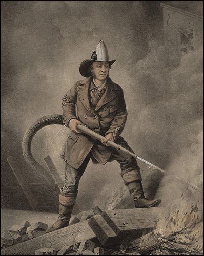
Understanding how to develop fire streams has been critical since firefighters began to use hose and nozzles (Figure 1) to increase the effectiveness and efficiency of firefighting operations.

Figure 1. In the Beginning!
fireman

When selecting handline nozzles, firefighters and fire officers generally consider four nozzle characteristics: 1) type of nozzle (combination or solid stream/smoothbore), 2) fixed or variable flow, 3) flow rate, and 4) designed operating pressure. Saving the big debate regarding combination and solid stream/smoothbore nozzles for another post, this post will focus primarily on nozzle pressure and flow rate.

Nozzle Function

A little over 20 years ago I was asked an interesting question by a newly hired recruit firefighter. She had no prior fire service experience and was puzzled by the hose evolutions being taught during her academy. As I attempted to help her make sense of these alien concepts, she finally asked “What’s the pump for? Why don’t we just put the nozzle on the end of the hose from the hydrant?” Her instructors may have assumed that hydraulics was a topic for apparatus operators or that everyone understood the basic concepts involved in developing an effective fire stream.

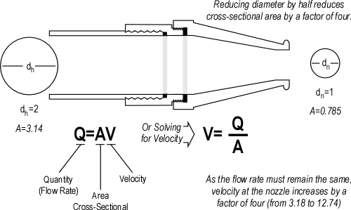
The primary function of a nozzle is to increase the velocity of water flowing from the hoseline. A fire stream must have sufficient velocity for water to reach from the nozzle to the intended target. The simple equation illustrated in Figure 2 is essential to understanding nozzle design and performance. Flow rate (the quantity of water) from a nozzle is dependent on the area of the opening and the velocity of the water being discharged (for a given size opening, the greater the velocity the higher the flow rate).

Figure 2. Important Equation
qav_nozzle_purpose

As indicated in the equation Q=AV, flow rate is related to velocity and the size (area) of the nozzle orifice. This relationship is simple to understand when looking at solid stream/smoothbore nozzles. Nozzle pressure translates to velocity at the tip. For a given size tip, increasing nozzle pressure increases velocity and thus the flow rate from the tip. For example, a 1-1/4” (32 mm) tip will flow 317 gpm (1200 lpm) at 50 psi (345 kPa). Increasing the nozzle pressure to 80 psi (552 kPa) increases the flow rate to 401 gpm (1518 lpm). Flow rate can be varied by changing the size of the tip, the nozzle pressure, or both.

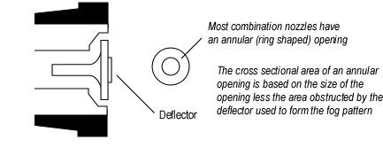
Visualizing nozzle orifice size is a bit more difficult with combination nozzles. Most combination nozzles use a deflection stem (see Figure 3) to form the fog pattern. The nozzle orifice is an annular (ring shaped) space between the deflector and the body of the nozzle tip.

Figure 3. Combination Nozzle Orifice
combination_nozzle_orifice

The change in direction at the deflection plate results in formation of small droplets of water. Nozzles may also have fixed teeth or a spinning, toothed turbine to aid in the production of appropriate sized droplets as water leaves the nozzle.

Nozzle Pressure and Droplet Size

Water is an excellent extinguishing agent because it has a high specific heat (energy required to raise its temperature) and high latent heat of vaporization (energy required to change it from water to steam). Of these two factors, conversion of water to steam is most significant as it absorbs 7.5 times more energy than heating water from 20o C (68o) to its boiling point. The firefighters’ power is not simply related to flow rate, but flow rate effectively applied to transfer heat from hot gases and surfaces by changing its phase from liquid (water) to gas (steam). Extinguishing a compartment fire generally involves converting a sufficient flow (gpm or lpm) of water to steam. So while the “steam” itself does not generally extinguish the fire, the energy absorbed in turning the water to steam has the greatest impact on fire extinguishment

Where the water is vaporized into steam depends on the method of fire control being used (direct attack, indirect attack, or 3D gas cooling). In direct attack water is vaporized on burning and pyrolyzing fuel surfaces to slow and stop the process of pyrolysis. Water is also vaporized on contact with hot surfaces in an indirect attack, but in this case the purpose is to produce a sufficient volume of steam to fill the compartment, achieving fire control or mitigating potential for extreme fire behavior such as a backdraft. Gas cooling on the other hand requires that the majority of the water be vaporized in the hot gas layer. This cools the hot gases (fuel) overhead, providing buffer zone and safer work environment for firefighters. It is important to remember that gas cooling is not an extinguishing technique, but merely one tool in controlling the fire environment.

Heat moves from objects of higher temperature to objects of lower temperature until temperature equalizes. Key factors in the speed of heat transfer are the difference in temperature and surface area of the materials. In the fire environment, burning fuel, nearby surfaces, and hot gases are considerably higher temperature than the water used for fire control and extinguishment. Surface area of the water in contact with the material being cooled is extremely significant in determining the speed of heat transfer. A larger surface area in relation to the amount of water will result in faster heat transfer and more rapid cooling.

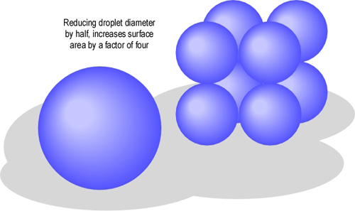
If the volume of water remains the same, reducing droplet size increases surface area substantially. For example if droplet size is reduced by half, surface area increases by a factor of four (see Figure 4).

Figure 4. Droplet Diameter and Surface Area
surface_area_sphere

Note. Adapted from Water and Other Extinguishing Agents (p. 194) by Stefan Särdqvist, 2002, Karlstad, Sweden: Raddningsverket. Copyright 2002 by Stefan Särdqvist and the Swedish Rescue Services Agency

Increased surface area increases heat transfer as droplets travel through the hot gas layer, rapidly reducing temperature. However, the down side of smaller droplets is that they do not travel as far and may not be able to penetrate a large distance in an extremely hot environment, making a fog pattern with small droplets potentially less effective in direct attack or when working in an extremely large compartment. Fortunately, when a fog pattern is adjusted to a straight stream much (but not necessarily all) of this problem is overcome.

What does nozzle pressure have to do with droplet size? Nozzles do not produce uniform droplet sizes. The fog pattern developed by a typical combination nozzle produces a mix of small and larger droplets. However, average droplet size and the percentage of droplets that are 0.3 mm (0.012”) in diameter is dependent on both nozzle design and pressure. However, for any nozzle design, increased nozzle pressure will result in smaller droplets.

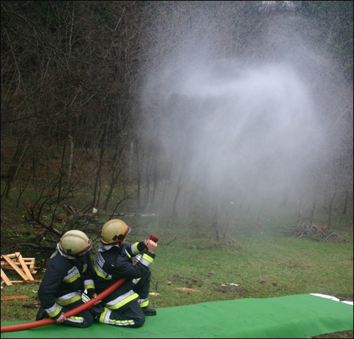
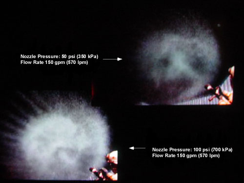
Gresham Fire & Emergency Services conducted a series of qualitative tests on droplet size produced by the Task Force Tips Dual-Pressure Mid-Force Nozzle operating at 50 psi (345 kPa) and 100 psi (689 kPa). Droplet size was assessed by examining hang time, the time which droplets remained suspended in the air after a short pulse of water fog (smaller droplets remain suspended for a longer time while large droplets fall to the ground more quickly). Results of this test were captured on video and synched to ensure that the visual comparison was at the same time after the nozzle was closed. As illustrated in Figure 5, with the same flow rate, the nozzle pressure of 50 psi (345 kPa) resulted in larger droplets than a nozzle pressure of 100 psi (689 kPa).

Figure 5.
High and Low Nozzle Pressure Test

Nozzles operating at a lower pressure will have larger droplet size. This does not impact substantially on direct attack, but can have a significant impact on the effectiveness and efficiency of these nozzles when used for gas cooling. This does not mean that they cannot be used! It simply means that they will be less effective and are likely to result in less efficient vaporization of water (more water will end up on the floor).

Impact on Operations

While it is important to understand the underlying principles related to nozzle design and performance, it is even more important to understand the impact of these concepts on firefighting operations. The next post in this series will examine the concepts of efficiency and effectiveness in greater depth and why effective cooling capacity may be more important than simply looking at flow rate.

Ed Hartin, MS, EFO, MIFireE, CFO

References

Särdqvist, S. (2002). Water and other extinguishing agents. Karlstad, Sweden: Raddningsverket (Swedish Rescue Services Agency).

Nozzle Techniques & Hose Handling: Part 2

Thursday, November 12th, 2009

Prior posts in this series, My Nozzle and Basic Nozzle Techniques & Hose Handling, examined the importance of proficiency in use of the firefighters’ primary weapon in offensive firefighting operations.

This is my nozzle, there are many like it but this one is mine. My nozzle is my best friend. It is my life. I must master it as I master my life. Without me it is useless, without my nozzle I am useless.

I will use my nozzle effectively and efficiently to put water where it is needed. I will learn its weaknesses, its strengths, its parts, and its care. I will guard it against damage, keep it clean and ready. This I swear [adapted from the Riflemans Creed, United States Marine Corps].

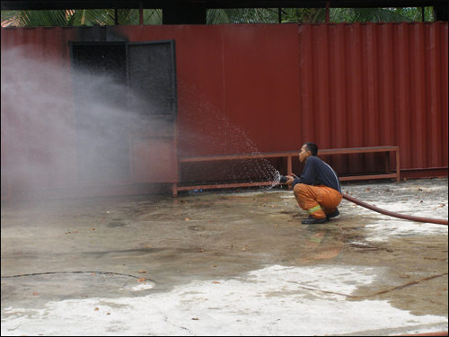
It is critical that firefighters have both a sound understanding of nozzle performance and skill in the use of their primary weapon. In Figure 1, Assistant Superintendent Mohamed Roslan Bin Zakaria, Bomba dan Penylamat, Malaysia examines stream characteristics from an Akron Turbojet. Note the change in droplet size as the nozzle is closed (droplet size increases as pressure drops). In a short pulse opening and closing the nozzle quickly minimizes production of large droplets that are unlikely to vaporize in the hot gas layer. In long pulses, closing the nozzle slowly increases the percentage of large droplets, but this is a necessary tradeoff to prevent excessive water hammer.

Figure 1. Determining Stream Characteristics

roslan_turbojet_practice

Note: Photo by Shan Raffel, ASFM, CMIFireE, EngTech.

This post continues with a discussion of training methods that can be used to develop proficiency in nozzle techniques and hose handling while deploying hoselines and in compartments having varied configurations. Continuing with our military metaphor, we will be practicing fire and maneuver.

Instructional Concepts

As discussed in Basic Nozzle Techniques and Hose Handling this sequence of drills is designed using the Simplifying Conditions Method (Reigeluth, 1999). This approach moves from simple to complex, beginning with the simplest version of the task that represents the whole and moves to progressively more complex versions until the desired level of complexity is reached. In the case of nozzle technique and hose handling, this involves moving from basic, individual skills, to team skills, and on to integration of physical skills and decision-making.

While modeling a specific technique (such as the short pulse) can be helpful in aiding the learners in developing basic skill, there is a danger. Technique is often mimicked without thought to why it is performed in a particular manner under specific circumstances. Demonstration of a short pulse with a 40o fog pattern (which might be appropriate in a small room) becomes “that is how all short pulses must be performed”. As the learners complete Hose and Nozzle Technique Drills 2 and 3, it is critical to provide changing conditions and encourage the learners to adapt their technique based on conditions.

Drill 2-Hose Handling and Nozzle Operation: Firefighters often lose focus on nozzle technique and operation when they are moving. This drill provides an opportunity for the firefighter with the nozzle and backup firefighter to develop a coordinated approach to movement and operation.

Hose Handling & Nozzle Technique Drill 2 Instructional Plan

Drill 3-Nozzle Operation Inside Compartments: Deployment of hoselines inside a building requires a somewhat different set of skills than simply moving forward and backward. Movement of hoselines around corners and adjustment of nozzle pattern to cool gases in hallways and varied size compartments are important additions to the firefighters’ skill set and provide the next step in developing proficiency in nozzle use.

Hose Handling & Nozzle Technique Drill 3 Instructional Plan

Battle Drills

Analysis of firefighter line-of-duty deaths (LODD) during structural firefighting operations points to the need for highly disciplined, immediate, and appropriate response to rapidly deteriorating conditions. In terms of military small unit tactics, battle drills provide a standardized, collective action rapidly executed without application of a deliberate decision making process (US Army, 1992).

Adapted to firefighting operations, Battle Drills:

  • Require minimal leader orders to accomplish and are standard throughout the department
  • Are sequential actions vital to success in firefighting operations or critical to preserving life
  • Apply to individual companies or teams
  • Are trained responses to changing conditions or leader’s orders
  • Represent mental steps followed for actions followed in training and firefighting operations

As a starting point for discussing this concept, give some thought to what situations might require a pre-planned and trained set of actions during offensive firefighting operations. For example, this might apply to locating a victim while deploying a hoseline for fire attack, rapidly deteriorating conditions, breathing apparatus malfunction, etc. Also consider how hose handling and nozzle techniques might apply in each of these situations.

Ed Hartin, MS, EFO, MIFireE, CFO

References

Reigeluth, C. (1999). Elaboration theory: Guidance for scope and sequence decisions. In C.M. Reigeluth (Ed.) Instructional-design theories and models: A new paradigm of instructional theory volume II. Mawah, NH: Lawrence Erlbaum Associates.

United States (US) Army. (1992). FM 7-8 Infantry rifle platoon and squad. Washington, DC: Headquarters, Department of the Army

Basic Nozzle Techniques and Hose Handling

Monday, November 2nd, 2009

The previous post in this series, My Nozzle, examined the importance of nozzle knowledge and skill in using the firefighter’s primary weapon in offensive firefighting operations.

Figure 1. Practice is Essential to Effective Nozzle Technique

nozzle_practice

Note: These Fire Officers from Rijeka, Croatia are practicing the short pulse to place water fog into the hot gas layer. Droplet size, cone angle, position of the nozzle, and duration of application have placed water in the right form exactly where it was intended.

This is my nozzle, there are many like it but this one is mine. My nozzle is my best friend. It is my life. I must master it as I master my life. Without me it is useless, without my nozzle I am useless.

I will use my nozzle effectively and efficiently to put water where it is needed. I will learn its weaknesses, its strengths, its parts, and its care. I will guard it against damage, keep it clean and ready. This I swear [adapted from the Riflemans Creed, United States Marine Corps].

This post continues with a discussion of training methods and techniques that can be used to develop proficiency in nozzle techniques and hose handling.

Limitations in Fire Service Instructional Methods

Fire service instructor training and related instructional methods have direct linkage to the philosophy of vocational education that evolved in the United States in the early 1900s (Hartin, 2004). The philosophy of vocational education that evolved in the first half of the 20th century put forth a mechanistic view of training and vocational education in which the goal is efficient production of trained individuals (Allen, 1919; Prosser & Allen, 1925). In early fire service instructor training, basic concepts of vocational education were combined with behaviorist psychological concepts of positive and negative reinforcement to guide learning. Over the last four decades, fire service instructor training has evolved to include humanist perspectives on motivation and the characteristics of adult learners. However, the basic principles used in training factory workers to perform simple repetitive tasks remain the meat and potatoes of this theoretical stew. All very interesting, but what does this have to do with nozzle technique?

The dominant focus of most fire service instructor training programs is on classroom instruction and to a lesser extent on demonstration of basic skills as an instructional method. Less focus is placed on effective methods for skills instruction (other than demonstration) and more importantly how to coach and provide effective feedback during skills instruction. Effectively and efficiently developing firefighters’ psychomotor skills requires a somewhat different focus.

There is a commonality between firefighters and athletes. Both require development of a wide range of physical and mental skills as well as underlying knowledge. A tremendous amount of research has been conducted on effective approaches to development of skill and proficiency in sport. Kinesiology (the science of human movement) and sport psychology provide a useful starting point for improving fire service skills training. While this post is focused on nozzle techniques and hose handling, the underlying theories can be applied to many other skills. It is essential that both the coach and the learner not only understand what needs to be done and how to do it, but why!

Motor Learning and Performance

A motor skill can be conceptualized as a physical task such as operating a nozzle or stretching a charged hoseline through a building. However, there are a number of dimensions on which these types of task can be classified:

  • Task organization (simple, single task or multiple, interconnected tasks)
  • Importance of motor and cognitive elements (doing or thinking)
  • Environmental predictability (consistent or variable conditions)

Simply opening and closing the nozzle is a discrete task that predominantly involves motor skill, and takes place in a fairly predictable environment (the firefighters’ position may change, but the nozzle remains the same). However, when placed in the context of hoseline deployment inside a structure with variable fire conditions things change quite a bit. This involves serial (multiple, sequential) tasks and requires both physical and cognitive (decision-making) skills, in a somewhat predictable, but highly variable environment. This explanation makes things seem a bit more complicated than they appear at first glance!

Motor learning can be divided into several relatively distinct stages (Schmidt & Wrisberg, 2008). In the verbal-cognitive stage, learners are dealing with an unfamiliar task and spend time talking and thinking their way through what they are trying to do. As learners progress to the motor stage, they have a general idea of the movement required and shift focus to refining their skill. Progression through the motor stage often requires considerable time and practice. Some learners progress to the autonomous stage in which action is produced almost automatically with little or no attention. Other than the newest recruits, most firefighters are in the motor stage of learning when developing skill in nozzle techniques and hose handling.

Developing an understanding of motor performance and learning requires a conceptual model. However, in that many of you are likely to be less excited about learning theory than I am, I will make an effort to limit this to a simple framework.

  1. Stimulus Identification: Recognize the need for physical action
  2. Response Selection: Determination of the action needed.
  3. Response Programming: Preparation and initiation of the required action.
  4. Feedback: Determination of the effectiveness of the action (this loops back to stimulus identification and the process begins again).

In some cases, feedback is obtained during the action and corrective action can be taken during task performance (closed loop control). In other (shorter duration) tasks, feedback is received after the task is completed (open loop control)

Many nozzle techniques such as application of a short pulse of water fog into the hot gas layer involve open loop control as the action is completed before the firefighter can receive and process feedback on the effectiveness of the action. Training must develop sufficient skill (and preferably automaticity) to allow firefighters to apply various nozzle techniques with minimal conscious thought to allow focus on maintaining orientation in the building and key fire behavior indicators.

While there is much more to the story, this limited explanation of motor learning and performance provides a starting point to understand why the nozzle technique and hose handling drills are important and why they are designed the way that they are.

Nozzle Technique and Hose Handling Drills

One more bit of learning theory before we get our hands on the nozzle. This sequence of drills is designed using the Simplifying Conditions Method (Reigeluth, 1999). This approach moves from simple to complex, beginning with the simplest version of the task that represents the whole and moves to progressively more complex versions until the desired level of complexity is reached. In the case of nozzle technique and hose handling, this involves moving from basic, individual skills, to team skills, and on to integration of physical skills and decision-making.

Once basic proficiency is developed in simple tasks (such as the short pulse, long pulse, penciling, and painting), practice should be randomly sequenced (rather than blocked into practice of a single skill). In addition, practice should be distributed over a number of shorter sessions, rather than massed into fewer, but longer sessions. For more information on design of effective and efficient practice sessions, see Motor Learning and Performance (Schmidt & Wrisberg, 2008).

Drill 1-Basic Skills in Nozzle Operation: The starting point in developing a high level of proficiency in nozzle use is to gain familiarity with the nozzle(s) you will be using including performance characteristics such as flow rate, operating pressure, and nozzle controls (i.e., shutoff, pattern, flow). In addition, firefighters should build skill in basic nozzle techniques such as the short pulse, long pulse, penciling, and painting while in a fixed position. Click on the following link to download the instructional plan for Drill 1 in PDF format.

Hose and Nozzle Technique Drill 1 Instructional Plan

Firefighting is team based. After firefighters have demonstrated individual proficiency in basic nozzle techniques from a fixed position, the next step is to apply these techniques in a team context.

Drill 2-Hose Handling and Nozzle Operation: Firefighters often lose focus on nozzle technique and operation when they are moving. This drill provides an opportunity for the firefighter with the nozzle and backup firefighter to develop a coordinated approach to movement and operation.

Drill 3-Nozzle Operation Inside Compartments: Deployment of hoselines inside a building requires a somewhat different set of skills than simply moving forward and backward. Movement of hoselines around corners and adjustment of nozzle pattern to cool gases in hallways and varied size compartments are important additions to the firefighters’ skill set and provide the next step in developing proficiency in nozzle use.

Drills 2 and 3 will be addressed in the next post in this series. Subsequent posts will address door entry procedures, indirect attack, and will introduce the concept of battle drills to build skill in dealing with worsening conditions or other emergencies while operating inside burning buildings.

Master Your Craft

Ed Hartin, MS, EFO, MIFIreE, CFO

References

Hartin, E. (2004). Theoretical foundations of fire service instructor training (unpublished manuscript available from the author). Portland State University.

Allen, C. R. (1919). The instructor the man and the job. Philadelphia, PA: J. B. Lippencott Company. Prosser, C. A., & Allen, C. R. (1925). Vocational education in a democracy. New York: The Century Company.

Schmidt, R. & Wrisberg, C. (2008). Motor learning and performance (4th ed.). Champaign, IL: Human Kinetics.

Reigeluth, C. (1999). Elaboration theory: Guidance for scope and sequence decisions. In C.M. Reigeluth (Ed.) Instructional-design theories and models: A new paradigm of instructional theory volume II. Mawah, NH: Lawrence Erlbaum Associates.

Wind Driven Fires: Tactical Problem

Monday, March 16th, 2009

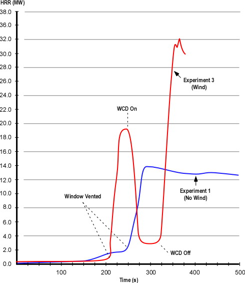
My last post examined National Institute for Standards and Technology (NIST) tests of wind control devices to mitigate hazards presented during wind driven compartment fires (Fire Fighting Tactics Under Wind Driven Conditions). Heat release rate (HRR)  data from Experiment 1 (baseline test with no wind) and Experiment 3 (wind driven) illustrates the dramatic influence of increasing ventilation to a ventilation controlled fire and even more dramatic impact when increased ventilation is coupled with wind (see Figure 1). This post posed several questions related to the HRR data from these experiments.

Figure 1. Heat Release Rates in Experiments 1 (Baseline) and 3 (Wind Driven)

hrr_experiment3Note: Adapted from Firefighting Tactics Under Wind Driven Conditions.
Questions

Examine the HRR curves in Figure 1 and answer the following questions:

  • What effect did deployment of the wind control device have on HRR and why did this change occur so quickly?
  • How did HRR change when the wind control device was removed and why was this change different from when the window was vented?
  • What factors might influence the extent to which HRR changes when ventilation is increased to a compartment fire in a ventilation controlled burning regime?

Answers: Application of the wind control device rapidly decreased heat release rate from approximately 19 MW to 5 MW. With the window covered, the fire lacked sufficient oxygen to maintain the higher rate of HRR. As oxygen was quickly consumed (and oxygen concentration was decreased) by the large volume of flaming combustion in the compartments, heat release rate was rapidly reduced.

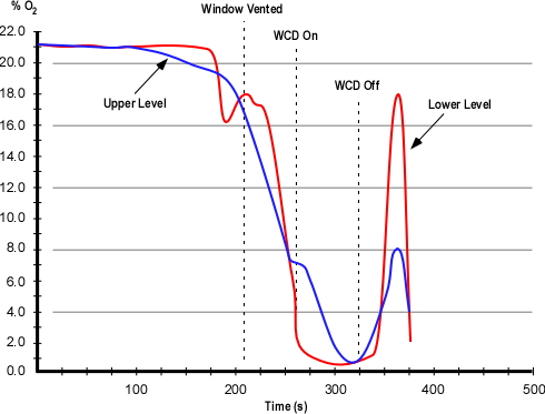
As with the change in HRR when the window was vented, removal of the wind control device resulted in an extremely rapid increase in HRR as additional oxygen was provided to the ventilation controlled fire inside the structure. In this case, the increase was even more significant with the peak HRR reaching approximately 32 MW. Examination of the oxygen concentration curve provides a hint of why this might have been the case (see Figure 2). The oxygen concentration was higher before the window was vented than when the wind control device was removed. The more rapid and greater rise in HRR is likely a result of the extent to which the fire was ventilation controlled and the available concentration of gas phase fuel. After the wind control device was removed, note that the oxygen concentration increased sharply (which relates to the rapid increase in HRR), followed by a rapid decrease as ventilation was inadequate to maintain that rate of combustion.

Figure 2. Oxygen Concentration in the Bedroom

o2_bedroom_test31

Note: Adapted from Firefighting Tactics Under Wind Driven Conditions.
Practical Application

The results of the NIST research are extremely interesting to students of fire behavior. However, it is essential that we be able to transform this information into knowledge that has practical application. This gives rise to three fundamental questions:

  • How do changes in ventilation influence fire behavior? Note that this is always a concern, not just under wind conditions!
  • What impact will wind have if the ventilation profile changes?
  • What tactical options will be effective in mitigating hazards presented by extreme fire behavior under wind driven conditions?

It is important to consider air track and the flow path from inlet to exhaust opening and the potential consequences of introducing air under pressure without (or with an inadequate) exhaust opening. Both can have severe consequences!

Tactical Problem

One good way to wrestle with the influence of wind on compartment fire behavior is to put it into a realistic context. In the following tactical problem you will be presented with an incident scenario and a series of questions. Apply what you have learned and consider how you would approach this incident.

Resources: You have what you have! Use your normal apparatus assignment and staffing levels when working through this tactical problem.

Weather Information: Conditions are clear with a temperature of 20o C (68o F) and a 24 kph (15 mph) wind out of the Northwest.

Dispatch Information: You have been dispatched to a residential fire at 0700 on a Sunday morning. The caller reported seeing smoke from a house at 1237 Lakeview Drive. After companies go enroute, the dispatcher provides an update that she is receiving multiple calls for a fire at this location.

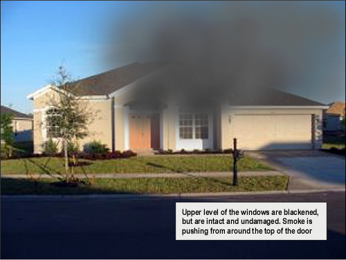
Conditions on Arrival: Approaching the incident location you observe a moderate volume of medium gray smoke from a wood frame, single family dwelling (most structures in this area are of lightweight construction). Smoke is blowing towards the A/D corner of the structure. As illustrated in Figure 3, smoke is visible from the front entry (window and door) of the house and it appears that smoke is showing from Side C as well. On closer examination, you observe that the upper level of the windows on Side A are stained with condensed pyrolysis products, but are intact.

Figure 3. View from Side A

wind_a

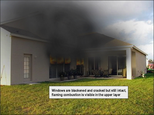
360o Reconnaissance: Moving down Side B, you observe a substantial body of fire in the center of the house. Smoke is pushing from around several sliding glass doors on Side B (see Figure 4) and flames are visible in the upper layer. The glass in the sliding doors is blackened and cracked, but is still intact. Smoke is also visible from around a large window on Side B Floor 2. Smoke discharge on Side B is swirling and being pushed up over the roof by the wind.

Figure 4. View from the BC Corner

wind_bc

Proceeding around the structure to Sides C and D, you observe a small amount of smoke pushing out from around the windows on Side D.

Questions: The first set of questions deals with size-up and development of an initial plan of action.

  • What B-SAHF indicators do you observe in Figures 2 and 3?
  • What stage(s) of fire development is (are) likely to exist in the structure?
  • What burning regime is the fire in?
  • How is the fire likely to develop in the time that it will take to develop and implement your incident action plan?
  • Would you have given orders to your crew (or would they have taken pre-planned standard actions) based on your observation of conditions on Side A (Figure 1)? If so what would have been done? Why?
  • Would your action plan have changed based on your observations from the B/C corner? What would you do differently? Why?
  • What is your action plan at this point? Do you have sufficient resources? What orders would you give the first alarm companies? What actions would you have your crew take? Why?

Your action plan is dependent on size-up and assessment of incident conditions.  Variation in conditions may result in a change in the priority or sequence of tactical action. Would your action plan have been different if the dispatcher had indicated that the caller was trapped in the house? If it would have, what would you have done differently? Why?

Things to Think About

This tactical problem presents a number of challenges. Click on the link to examine the Floor Plan and then consider the following questions:

  • What conditions would firefighters have encountered if they made entry through the door on Side A (front door)? Why?
  • How would these conditions have changed if glass in one or more of the sliding doors on Side B had failed after firefighters had made entry? Why?
  • What conditions would have resulted if the glass in one or more of the sliding doors on Side B had failed and the door on Side A was not open? Why?
  • What options for fire attack and tactical ventilation would have been effective in this situation? Would your choice fire attack and tactical ventilation location, sequence, and coordination have varied based on the report of occupants? Why?
  • How did your knowledge of the results of the NIST tests on wind driven fires impact your understanding of this incident? How did this understanding influence your tactical decision-making?

It is important to practice strategic and tactical decision-making. However, it is also important to think about how and why we make these decisions. This meta-learning (learning about our learning) has a significant impact on our professional development and ability to learn our craft.

Remember the Past

As discussed in previous posts, it is important to honor the sacrifices of firefighters who have died in the line of duty and not lose lessons learned as time passes. The following narratives were taken from the United States Fire Administration (USFA) reports on Firefighter Line of Duty Deaths (1994 and 2004).

March 29, 1994
Captain John Drennan, 49, Career
Firefighter James Young, 31, Career
Firefighter Christopher Seidenburg, 25, Career
Fire Department of the City of New York, New York

On March 29, three firefighters trapped in the stairwell of a brownstone were burned when they were enveloped in fire while attempting to force their way through a heavy steel door to a second floor apartment. Captain John Drennan, Firefighter James Young, and Firefighter Christopher Seidenburg of the New York City Fire Department were conducting a search when the hot air and toxic gases that collected in the stairwell erupted into flames as other fire crews forced entry into the first floor apartment where the fire had originated. The fire exhibited characteristics of both a backdraft and a flashover. Firefighter Young, in the bottom position on the stairs, was burned and died at the scene. Firefighter Seidenberg and Captain Drennan were rescued by other firefighters. They were transported to a burn unit with third and fourth degree burns over 50 of their bodies. Seidenburg died the next day. Drennan passed away several weeks later. The fire cause was determined to be a plastic bag left by the residents on top of the stove of the floor apartment.

For additional information on this incident see:

Bukowski, R. (1996). Modeling a backdraft: The 62 Watts Street incident. Retrieved March 14, 2009 from http://fire.nist.gov/bfrlpubs/fire96/PDF/f96024.pdf

March 21, 2003 – 0850
Firefighter Oscar “Ozzie” Armstrong, III, Age 25, Career
Cincinnati Fire Department, Ohio

Firefighter Armstrong and the members of his fire company responded to the report of a fire in a two-story residence. The first fire department unit on the scene, a command officer, reported a working fire.

Firefighter Armstrong assisted with the deployment of a 350-foot, 1-3/4-inch handline to the front door of the residence. Once the door was forced open, firefighters advanced to the interior. The handline was dry as firefighters advanced; the hose had become tangled in a bush.

As the line was straightened and water began to flow to the nozzle, a flashover occurred. The firefighters on the handline left the building and were assisted by other firefighters on the front porch of the residence. All firefighters were ordered from the building, air horns were sounded to signal a move from offensive to defensive operations.

Several firefighters saw Firefighter Armstrong trapped in the interior by rapid fire progress. These firefighters advanced handlines to the interior and removed Firefighter Armstrong. A rapid intervention team assisted with the rescue.

Firefighter Armstrong was severely burned. He was transported by fire department ambulance to the hos­pital where he later died.

The origin of the fire was determined to be a pan of oil on the stove.

For additional information on this incident see:

National Institute for Occupational Safety and Health (NIOSH). (2005). Death in the line of duty report F2003-12. Retrieved March 14, 2009 from http://www.cdc.gov/niosh/fire/pdfs/face200312.pdf

Laidlaw Investigation Committee. (2004)Line of duty death enhanced report Oscar Armstrong III March 21, 2004. Retrieved March 14, 2009  from http://www.iafflocal48.org/pdfs/enhancedloddfinal.pdf

Ed Hartin, MS, EFO, MIFireE, CFO

References

Madrzykowski, D. & Kerber, S. (2009). Fire fighting tactics under wind driven conditions. Retrieved (in four parts) February 28, 2009 from http://www.nfpa.org/assets/files//PDF/Research/Wind_Driven_Report_Part1.pdf; http://www.nfpa.org/assets/files//PDF/Research/Wind_Driven_Report_Part2.pdf;http://www.nfpa.org/assets/files//PDF/Research/Wind_Driven_Report_Part3.pdf;http://www.nfpa.org/assets/files//PDF/Research/Wind_Driven_Report_Part4.pdf.

United States Fire Administration (USFA). (1995) Analysis report on firefighter fatalities in the United States in 1994. Retrieved March 14, 2009 from http://www.usfa.dhs.gov/downloads/pdf/publications/ff_fat94.pdf

United States Fire Administration (USFA). (2005). Frefighter fatalities in the United States in 2004. Retrieved March 14, 2009 from http://www.usfa.dhs.gov/downloads/pdf/publications/fa-299.pdf

NIST Wind Driven Fire Experiments:
Wind Control Devices & Fire Suppression

Thursday, March 12th, 2009

Continuing examination of NIST’s research on Firefighting Tactics Under Wind Driven Conditions, this post looks at the results of experiments involving use of wind control devices and external water application.

In my last post, I posed several questions about wind control devices to “prime the pump” regarding wind driven fires and potential applications for use of wind control devices.

Questions

Give some thought to how wind can influence compartment fire behavior and how a wind control device might mitigate that influence.

  • How would a strong wind applied to an opening (such as the bedroom window in the NIST tests) influence fire behavior in the compartment of origin and other compartments in the structure?
  • How would deployment of a wind control device influence fire behavior?
  • While the wind control device illustrated in Figure 5 was developed for use in high-rise buildings, what applications can you envision in a low-rise structure?
  • What other anti-ventilation tactics could be used to deal with wind driven fires in the low-rise environment?

Answers: Thornton’s Rule indicates that the amount of oxygen required per unit of energy released from many common hydrocarbons and hydrocarbon derivatives is fairly constant. Each kilogram of oxygen used in the combustion of common organic materials results in release of 13.1 MJ of energy. Fully developed compartment fires are generally ventilation controlled (potential heat release rate (HRR) based on fuel load exceeds the actual HRR given the atmospheric oxygen available through existing ventilation openings). Application of wind can dramatically increase heat release rate by increasing the mass of oxygen available for combustion. In addition to increasing HRR, wind can significantly increase the velocity of hot fire gases and flames (and resulting convective and radiant heat transfer) between the inlet and outlet openings.

Deployment of a wind control device to cover an inlet opening (window or door), limits oxygen available for combustion to the air already in the structure and normal building leakage. In addition, blocking the wind will also reduce gas and flame velocity between the inlet and outlet.

While wind driven fires are problematic in high-rise buildings, the same problem can be encountered in low-rise structures and wind control devices may prove useful in some circumstances. However, exterior attack (discussed later in this post) is more feasible than in a high-rise building and other tactics such as door control may also prove essential in managing hazards presented by wind.

Test Conditions

As outlined in my earlier post, Wind Driven Fires, NIST conducted a number of different wind driven tests using the same multi-compartment structure. Experiment 3 involved evaluation of anti-ventilation tactics using a large wind control device placed over the bedroom window. Wind conditions of 6.7 m/s to 8.9 m/s (15 mph-20 mph) were maintained throughout the test.

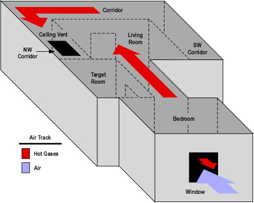
As with the baseline test, two ventilation openings were provided. A ceiling vent in the Northwest Corridor and a window (fitted with glass) in the bedroom (compartment of origin). During the test the window failed due to fire effects and was subsequently fully cleared by the researchers to provide a full window opening for ventilation.

Figure 1. Isometric Illustration of the Test Structure

test_floor_plan_wind

Note: The location of fuel packages in the bedroom and living room is shown on the Floor Plan provided in Wind Driven Fires post.

Experiment 3 Wind Driven Fire

This experiment was one of several that investigated wind driven fire behavior and the effectiveness of a wind control device deployed over the bedroom window to limit inward airflow. The fire was ignited in the bedroom and allowed to develop from incipient to fully developed stage in the bedroom.

The fire progressed in a similar manner as observed in the baseline test described in my earlier post NIST Wind Driven Fire Experiments: Establishing a Baseline. In this experiment the fire involving the initial fuel packages (bed and waste container) and visible smoke layer developed slightly more slowly. However, the bedroom window failed more completely and 11 seconds earlier than in the baseline test.

Almost immediately after the window failed, turbulent flaming combustion filled the bedroom and hot gases completely filled the door between the living room and corridor and were impinging on the opposite wall. At 222 seconds (15 seconds after the window was completely cleared) flames were visible in the corridor and the hollow core wood door in the target room was failing with flames breaching the top corners of the door and a smoke layer developing in the target room. While most of the hot gases and flames were driven through the interior (towards the ceiling vent in the corridor), flames continued to flow out the top of the window opening (against the wind).

At 266 seconds conditions had further deteriorated in all compartments with no visibility in the corridor and increased deterioration of the door to the target room. At this point the air track at the window was completely inward (no flames outside the window).

The wind control device was deployed at 270 seconds. Unfortunately soot on the video cameras lenses precluded a good view of interior conditions. However, video from the thermal imaging camera no longer showed any flow of hot gases into the corridor (only high temperature).

At 330 seconds, shortly after removal of the wind control device flames were visible in the bedroom and the fire quickly progressed to a fully developed state. At 360 seconds, flames were pulsing out the window opening (against the wind).

The experiment was ended at 380 seconds and the fire was extinguished.

Heat Release Rate

As with the baseline test NIST researchers recorded heat release rate data during Experiment 3. As discussed earlier in this post, application of wind increased the amount of oxygen available for combustion and resulting heat release rate in comparison to the baseline test.

Figure 2. Heat Release Rates in Experiments 1 (Baseline) and 3 (Wind Driven)

hrr_experiment3

Note: Adapted from Firefighting Tactics Under Wind Driven Conditions.
Questions: Examine the heat release rate curves in Figure 2 and answer the following questions:

  • What effect did deployment of the wind control device have on HRR and why did this change occur so quickly?
  • How did HRR change when the wind control device was removed and why was this change different from when the window was vented?
  • What factors might influence the extent to which HRR changes when ventilation is increased to a compartment fire in a ventilation controlled burning regime?

Wind Control Device Research and Application

NIST has continued research into the practical application of wind control devices with tests in Chicago and New York involving large apartment buildings and realistic fuel loading. For additional information on these tests and video of wind control device deployment, visit the NIST Wind Driven Fires webpage.

Fire Control Experiments

NIST researchers also conducted a series of experiments in the same structure examining the impact of various fire control tactics. These included application of water using solid stream and combination nozzles (using a 30o fog pattern with continuous application). In addition, they examined the influence of coordinated deployment of a wind control device and low flow water application of water fog). In each of these tests, water was applied from the exterior of the structure through the bedroom window.

Water Fog Application: Experiment 6 involved application of water using a hoseline equipped with a combination nozzle at 90 psi (621 kPa) nozzle pressure, providing a flow rate of 80 gpm (303 lpm). The fog stream was initially applied across the window (no discharge into the bedroom). This had a limited effect on conditions on the interior. When applied into the room, the 30o fog pattern was positioned to almost completely fill the window. This action resulted in a brief increase (approximately 4 MW) and then a dramatic reduction in HRR.

Solid Stream Application: Experiments 7 and 8 involved application of water using a hoseline equipped with a 15/16″ smooth bore nozzle at 50 psi (345 kPa) nozzle pressure, providing a flow rate of 160 gpm (606 lpm).  The solid stream was initially directed at the ceiling and then in a sweeping motion across the ceiling. In Experiment 8, the stream was then directed at burning contents in the compartment. Application of the solid stream had a pronounced effect, dramatically reducing heat release rate in both experiments.

Conditions varied considerably between these three tests (Experiments 6-8). This makes direct comparison of the results somewhat difficult. However, several conclusions can be drawn from the data:

  • Exterior application of water can be effective in reducing HRR in wind driven fires.
  • Both solid stream and fog application can be effective in reducing HRR under these conditions.
  • Continuous application of water fog positioned to nearly fill the inlet opening develops substantial air flow which can increase HRR (this works similar to the process of hydraulic ventilation, but in reverse).
  • A high flow solid stream may be more effective (but not necessarily more efficient) than a lower flow fog pattern if a direct attack on burning contents can be made.

Coordinated WCD Deployment and Water Application: Experiments 4 and 5 involved evaluations of anti-ventilation and water application using a small wind control device and 30 gpm (113.6 lpm) spray nozzle from under the wind control device. The effectiveness of the wind control device was similar to other anti-ventilation tests and application of low flow water fog resulted in continued decrease in HRR throughout the experiment.

Ed Hartin, MS, EFO, MIFireE, CFO

References

Madrzykowski, D. & Kerber, S. (2009). Fire Fighting Tactics Under Wind Driven Conditions. Retrieved (in four parts) February 28, 2009 from http://www.nfpa.org/assets/files//PDF/Research/Wind_Driven_Report_Part1.pdf; http://www.nfpa.org/assets/files//PDF/Research/Wind_Driven_Report_Part2.pdf;http://www.nfpa.org/assets/files//PDF/Research/Wind_Driven_Report_Part3.pdf;http://www.nfpa.org/assets/files//PDF/Research/Wind_Driven_Report_Part4.pdf.
Shielded Fires Part 2

Thursday, February 12th, 2009

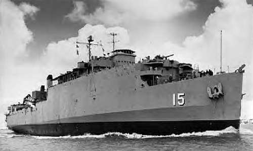
The previous post (Shielded Fires) examined US Navy research on the effectiveness of different nozzle techniques when dealing with shielded fires conducted on the ex-USS Shadwell, the US Navy full scale damage control research facility (see Figure 1).

Figure 1. USS Shadwell

uss_shadwell

The researchers tested two different methods for controlling flaming combustion overhead while moving from the entry point to a location in a compartment where firefighters could make a direct attack on the seat of the fire. The first method involved use of a straight stream or narrow fog pattern and the second involved the use of a medium (60o) fog pattern directed upward at a 45o angle. In both cases, one to three second pulses were used in application of water into the hot gas layer.

US Navy Findings

Analysis of this series of tests resulted in identification of a number of specific findings related to tactics, equipment, and training. Three of these findings were particularly relevant to the differences between straight stream/narrow fog and medium fog applied to control flaming combustion in the upper layer.

  • Pulsed application with a medium fog pattern directed upward at a 45o angle resulted in less disruption of the thermal layer than use of a straight stream/narrow fog pattern.
  • Use of a straight stream/narrow fog resulted in production of a large amount of steam. This was attributed to the fact that the hose streams had to be deflected compartment linings.
  • Water management is important when controlling fire in the upper layer, particularly when using a straight stream/narrow fog. Excess water will only result in excess steam production.

Discussing the findings, the researchers observed that pulsed application of medium fog appeared to be an effective tactic for controlling flaming combustion in the upper layer. This conclusion is supported by consistent reduction of upper layer temperature over the course of the tests involving use of pulsed application of a medium fog pattern.  Previous concerns that this approach would result disruption of thermal layering and excess steam production appeared to be unfounded. This conclusion is supported by the heat flux data at 0.9 M (7′ 10″) and 2.9 M (3′) above the floor. Disruption of thermal layering is indicated by an upward spike in lower level heat flux or equalization of heat flux at the lower and upper levels.

Questions

Several questions about the outcome of these tests were posed at the end of the Shielded Fires post.

  • Why did the application of water in a straight stream/narrow fog pattern fail to effectively control flaming combustion in the upper layer?
  • Why did the upper layer temperature fluctuate when a straight stream/narrow fog was used?
  • Why did the upper layer temperature drop consistently when a medium angle fog pattern was used?
  • How did the heat flux measurements correlate with the upper layer temperatures in these two tests?
  • What are the implications of the heat flux data recorded during these tests on tenability within the compartment for both firefighters and unprotected occupants?

Water converted to steam on contact with compartment linings or other hot objects cools the surfaces. This indirectly lowers gas layer temperature as the hot gases will continue to transfer heat to compartment linings and other cooler objects in an attempt to equalize temperature. However, the effect on upper layer temperature is limited, minimizing effectiveness of stream application in controlling flaming combustion in the upper layer. In addition, as gas temperature is not significantly reduced, steam produced on contact with hot surfaces is added to the volume of hot gases, resulting in a less tenable environment.

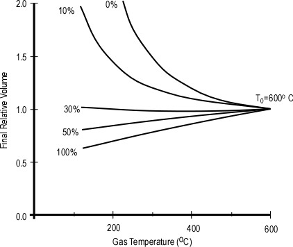
Ineffectiveness of straight stream/narrow fog attack in controlling flaming combustion in the upper layer and the perception of increased steam production with this type of attack likely have a common cause. Conversion of water to steam requires much more energy than simply heating water from ambient temperature to its boiling point. When water changes phase from liquid to gas (steam) while in the hot gas layer, the temperature of the gases is reduced. This has several consequences. First, sufficient reduction in temperature results in extinguishment of flaming combustion. Second, reduction of gas layer temperature causes a proportional reduction in gas volume. As illustrated in Figure 2, if 35% of the water is truned to steam in the hot gas layer, the total volume of steam and hot fire gases is less than the original volume of hot fire gases alone (Särdqvist, 2002). As this is often difficult to understand, I will provide a more detailed explanation of this in a subsequent post.

Figure 2. Gas Temperature and Relative Volume

gas-surfacecooling

Note. Adapted from Water and Other Extinguishing Agents (p. 155) by Stefan Särdqvist, 2002, Karlstad, Sweden: Raddningsverket. Copyright 2002 by Stefan Särdqvist and the Swedish Rescue Services Agency.

Production of the same volume of steam can have far different consequences depending on where it is produced (in the hot gas layer versus on contact with hot surfaces!

Total heat flux includes energy transferred through radiation, convection, and conduction. However, in these full scale fire tests, radiant and convective heat transfer was most significant. Radiant heat transfer is dependent on the temperature of upper layer gases and flaming combustion. Convective heat transfer is dependent on gas temperature, movement of hot gases, and moisture. Reduction in upper layer temperature while maintaining thermal layering minimizes total heat flux at the lower level where firefighters are working.

Other Considerations

These tests were conducted on a ship (see Figure 1) with most of the compartment linings being metal (rather than gypsum board, plaster, or wood as typically encountered in buildings. The fire compartment did not have windows or other ventilation openings that may exist in more typical buildings encountered by structural firefighters. These differences are significant, but do not diminish the importance of the results of these tests and findings by the researchers.

These tests provide substantive evidence in support of the effectiveness of water converted to steam in the hot gas layer (as opposed to on surfaces) in controlling flaming combustion in the hot gas layer. However, this does not diminish the importance of direct application of water onto burning fuel in a direct attack to complete the process of extinguishment.

Reference

Särdqvist, S. (2002). Water and other extinguishing agents. Karlstad, Sweden: Swedish Rescue Services Agency.

Scheffey, J., Siegmann, C., Toomey, T., Williams, F., & Farley J. (1997) 1994 Attack Team Workshop: Phase II-Full Scale Offensive Fog Attack Tests, NRL/MR/6180-97-7944. Washington, DC: United States Navy, Naval Sea Systems Command

Remember the Past

In Myth of the Self-Vented Fire I pointed out that every week represents the anniversary of the death of one or more firefighters as a result of extreme fire behavior. Some firefighters have heard about these incidents, but many have not. In an ongoing effort to encourage us to remember the lessons of the past and continue our study of fire behavior, I will occasionally be including brief narratives and links to NIOSH Death in the Line of Duty reports and other documentation in my posts.

February 11, 1998 – 1030
Firefighter Paramedic Patrick Joseph King
Firefighter Anthony E. Lockhart
Chicago Fire Department, Illinois

Firefighter King and Firefighter Lockhart responded on different companies to a report of a structural fire in a tire shop. No visible fire was encountered, there was no excessive heat, and only light smoke was found in most of the building with heavier smoke in the shop area. Ten firefighters were in the interior of the structure when an event that has been described as a flashover or backdraft occurred. The firefighters were disoriented by the effects of the backdraft. Some were able to escape but Firefighter King and Firefighter Lockhart were trapped in the structure. A garage door that self-operated due to fire exposure may have introduced oxygen into the fire area and may have been a factor in the backdraft. The exit efforts of firefighters were complicated by congestion in the building. Within minutes of the backdraft, the building was completely involved in fire and rescue efforts were impossible. Both firefighters died from carbon monoxide poisoning due to inhalation of smoke and soot. Further information related to this incident can be found in NIOSH Fire Fighter Fatality Investigation 98-F-05.

February 9, 2007
Firefighter-Paramedic Apprentice Racheal Michelle Wilson
Baltimore City Fire Department, Maryland

Firefighter Wilson and the members of her fire academy class were attending a live fire training exercise in a vacant rowhouse in Baltimore.

Firefighter Wilson was assigned to a group of apprentices and an instructor designated as Engine 1. Her group advanced a dry attack line into the structure. As they climbed the stairs, the line was charged. Engine 1 encountered and extinguished fire on the second floor but did not check the rest of the second floor for fire prior to proceeding to the third floor. On the third floor, they again encountered and began to extinguish fire.

Fire conditions began to worsen with a marked increase in smoke and heat that appeared to be coming from the second floor. Engine 1 firefighters who were on the stairs began to receive burns from the fire conditions. The instructor for Engine 1 climbed out a window at the top of the stairs and helped one burned firefighter escape to the roof.

Firefighter Wilson appeared at the window in obvious distress and attempted to escape. The windowsill was unusually high (41 inches) and she was unable to escape. Firefighter Wilson momentarily moved away from the window, at which time she advised other firefighters to go down the stairs to escape. When she returned to the window, her SCBA facepiece was off and she was beginning to receive burns. She was able to get her upper body out of the window but she could not make it through. Firefighters on the exterior were unable to pull her through until firefighters were able to gain access on the interior and assist with the effort.

When Firefighter Wilson was pulled to the roof, she was in full cardiac and respiratory arrest. She was immediately removed from the roof and received advanced life support care and transportation to the hospital. She was pronounced dead at 1250 hours. Firefighter Wilson received total body surface burns of 50 percent. The cause of death was listed as thermal burns and asphyxiation.

Further information related to this incident can be found in NIOSH Firefighter Fatality Investigation F2007-09 and the Independent Investigation Report on the Baltimore City Fire Department Live Fire Training Exercise, 145 South Calverton Road, February 9, 2007.

My next post will examine the incident in which Rachael Wilson lost her life in greater detail.

Ed Hartin, MS, EFO, MIFIreE, CFO

Shielded Fires

Monday, February 9th, 2009

Fire control and extinguishment is a fairly straightforward process when water can be applied directly to the burning fuel. In the case of burning ordinary combustibles, the energy required to heat the water to its boiling point and convert it to steam cannot be used to continue the process of pyrolysis and lowers fuel temperature to the point where the fire goes out.

However, this process is complicated when the fire is shielded from direct application of water. Assuming that an offensive strategy is appropriate, there are several options for attacking a shielded fire: 1) Make an indirect attack from the exterior (assuming you can access the involved compartment(s) from an exterior location) or 2) Move inside the building to a point inside the building where a an indirect attack can be made from outside the involved compartment(s), or 3) Move inside to a location where a direct attack can be initiated.

When adequate resources are available offensive attack from the interior addresses both life safety and fire control priorities. Proper hoseline placement and coordination of fire control and ventilation tactics protects civilian occupants and provides a safer work environment for firefighters.

The Ongoing Debate

The topic of fire stream selection (fog versus straight or solid stream) likely generates more energy than a fully developed compartment fire. Firefighters bring a great deal of passion based on experience, knowledge, and ignorance to the discussion.

There is not a single answer to the question of which type of fire steam is best. Fog and straight or solid streams have different performance characteristics and are best suited for different applications. Keep in mind that:

  • An effective fire stream puts the appropriate amount of water in the right form and right location to achieve the desired result.
  • An efficient fire stream accomplishes this with the smallest volume of water and least water damage.

Understanding the effectiveness and efficiency of fire stream application requires both qualitative and quantitative evidence. Firefighters can observe the effects of fire stream application and make a judgment as to effectiveness and efficiency. However, this understanding can be deepened by scientific examination that measures the impact of fire stream application methods.

US Navy Research

In 1994, the United States Navy conducted a series of tests to investigate the aggressive use of water fog for shipboard firefighting (Scheffey, Siegmann, Toomey, Williams, & Farley, 1997). Prior to this time, shipboard firefighting either involved direct attack with a straight stream or narrow fog pattern or indirect attack from outside the involved compartment. This series of tests compared the use of pulsed application of a medium (60o) fog pattern with use of a straight stream in controlling shielded fires and fire conditions involving high temperature and thick smoke conditions that impeded location of the seat of the fire.

The conditions (heat, smoke, and fire gases) associated with these fire scenarios typically does not prevent initial entry into the fire compartment. However, the extra time that it takes to maneuver within a space to locate and attack the seat of the fire does present a significant threat, primarily due to the stage of the fire. Uncontrolled, these fires may continue grow rapidly, potentially resulting in flashover conditions. This is particularly true where the fire is ventilation limited…and entry by the attack team introduces additional air [emphasis added].

While the Navy is concerned with shipboard firefighting, ventilation controlled, shielded fires are commonly encountered by structural firefighters as well.

Test Conditions

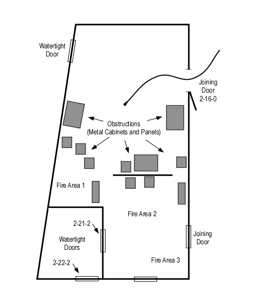
The tests were conducted on the ex-USS Shadwell, the Navy’s full-scale damage control research and development platform and involved several different fire scenarios. This post will examine tests involving Fire Threat 1, a growth stage fire involving multiple fuel packages within a compartment to create a well developed growth stage fire approaching flashover (upper layer temperatures in the range of 400o-600o C (752o-1152o F)). In addition, obstructions were placed to preclude the possibility of direct attack from the point of entry. Firefighters were required to control flames in the upper layer in order to penetrate deep enough into the compartment to make a direct attack on the fire.

Compartment Size and Configuration: The compartment used for the test was irregularly shaped (see Figure 2) with approximate dimensions of 8.5 M x 5.4 M (28′ x 17′ 7″) for an approximate floor area of 45.9 M2 (494 ft2).

Figure 1. Compartment Configuration

shadwell_floorplan

Fuel Load: Varied fuel types, including wood (red oak) cribs of varied dimensions, 1200 mm x 2400 mm (4′ x 8′) sheets of particle board (two layers of 6.4 mm particle board nailed together to provide a thickness of 13 mm (0.5″), and cardboard boxes of crumpled newspaper. All of the boxes were 457 mm x 381 mm x 305 mm (18″ x 15″ x 12″) and were taped closed after being loosely filled with newspaper. These fuel packages were distributed between three separate fire areas see (Figure 1).

  • Fire Area 1 included a triangular wood crib, three particleboard panels (placed vertically against the compartment walls), and nine cardboard boxes filled with newspaper. Fire in these fuel packages was initiated using 2.8 L (0.5 gallon) of heptanes in a 610 mm (24″) pan.
  • Fire Area 2 included a square wood crib and nine cardboard boxes filled with newspaper. Fire in these fuel packages was initiated using 18.9 L (5 gallons) of heptanes in a 914 mm (36″) square pan.
  • Fire area 3 included a rectangular wood crib and three particleboard panels (placed vertically against the compartment walls). Fire in these fuel packages was initiated using 2.8 L (0.5 gallon) of heptanes in a 610 mm (24″) pan.

Ventilation Profile: Temperature in the upper layer was monitored using thermocouples. Watertight Doors 2-22-2 and 2-21-2 were used to control the air supply to the fire and maintain consistent temperature conditions and flaming combustion in the hot gas layer for each test. When the attack team entered the compartment, air also entered the fire compartment through the entry point at Joining Door 2-16-0 (see Figure 1).

Tactical ventilation was not used in coordination with fire attack during these evolutions. The only ventilation provided while the attack team was engaged in firefighting operations involved the entry point as both exhaust and inlet opening.

Fire Control Procedures: In each of the tests the fire attack team used a 38 mm (1.5″) hoseline with a combination nozzle delivering 360 L/min (95 gpm) at 700 kPa (100 psi). For the pulsed water fog attack, the nozzle team applied oneto three second pulses with a 60o fog pattern directed upward at a 45o angle.  For the straight stream attack, the tactics were the same, but a straight stream or narrow fog pattern was used.

Note: It is important to note that the researchers and Navy firefighters involved in these tests considered a narrow fog pattern and straight stream equivalent within the context of shipboard firefighting. While the characteristics of a narrow fog pattern and straight or solid stream are different, both will penetrate through the hot gas layer and result in conversion of water to steam on contact with compartment linings (rather than within the hot gas layer)

The Tests

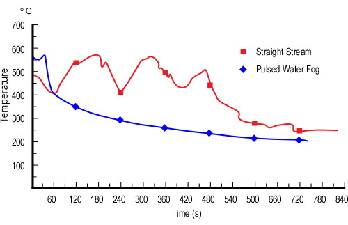
Test 14 was performed using traditional straight stream tactics. The nozzle operator applied two pulses with a narrow fog pattern in an attempt to control fire in upper layer. This water application produced a large amount of steam, but failed to control flaming combustion in the hot gases. After application of three more short pulses, the attack team moved to Fire Area 2 (see Figure 1) and commenced a direct attack on the fire in Fire Areas 2 and 3. However, 150 seconds (2 minutes 30 seconds) after commencing fire attack, the fire in Fire Area 1 reignited and flaming combustion in the hot gas layer caused the attack team to withdraw towards the entry point and attempt to regain control of the overhead fire. This was unsuccessful and the attack team withdrew to the entry point. A second attempt was made to enter and control the fire overhead using three long (five second) straight stream application from the doorway. These had minimal effect with continued flaming combustion overhead and involvement of fuel packages in all three fire areas. 420 seconds (seven minutes) after the initial attack, the evolution was terminated.

Test 17 replicated conditions used in Test 14, but pulsed application of a medium (60o) fog pattern was used to control fire in the upper layer, rather than a narrow fog/straight stream. Immediately after making entry, the nozzle operator applied three short pulses directed upward at a 45o Angle in the direction of Fire Area 2. The first pulse appeared to cause the flaming combustion to increase in Fire Area 2, but subsequent pulses controlled flaming combustion overhead. Visibility was reduced slightly, but the attack team was able to advance and make a direct attack on the seat of the fire. The fuel packages in Fire Area 1 reignited, but the fire was quickly controlled.

Influence on the Fire Environment

Quantitative data on factors such as upper level temperature and heat flux (heat transfer per unit area) within the compartment were recorded in addition to qualitative observations by the firefighters and researchers involved in the test. Figure 2 illustrates the temperature changes in the fire compartment during Tests 14 (straight stream/narrow fog) and 17 (medium angle fog) attacks.

Figure 2.  Average Upper Layer Temperature: Tests 14 and 17

shadwell_temp

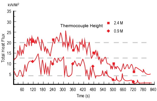
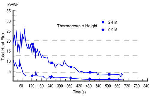
Total heat flux (e.g., radiant and convective) was recorded 2.4 M (7′ 10″) and 0.9 M (3′) above the floor. Figures 3 and 4 illustrate conditions recorded during Test 14 (straight stream/narrow fog) and Test 17 (medium angle fog).

The dashed gray lines are provided as a point of reference at 20 kW/m2, 12.5 kW/m2, and 4.5 kW/m2. These correspond to heat flux conditions required for rapid auto ignition of ordinary combustibles, sufficient pyrolysis for piloted ignition of ordinary combustibles, and second degree burns to exposed skin within 30 seconds respectively.

Figure 3. Heat Flux Test 14

shadwell_heatflux_ss

Figure 4. Heat Flux Test 17

shadwell_heatflux_fog

Questions

Based on the information on the US Navy tests presented in this post, consider the following questions:

  1. Why did the application of water in a straight stream/narrow fog pattern fail to effectively control flaming combustion in the upper layer?
  2. Why did the upper layer temperature fluctuate when a straight stream/narrow fog was used?
  3. Why did the upper layer temperature drop consistently when a medium angle fog pattern was used?
  4. How did the heat flux measurements correlate with the upper layer temperatures in these two tests?
  5. What are the implications of the heat flux data recorded during these tests on tenability within the compartment for both firefighters and unprotected occupants?

More to Follow

My next post will examine the answers to these questions and the conclusions reached by the Navy researchers as a result of this series of tests.

Ed Hartin, MS, EFO, MIFireE, CFO

References

Scheffey, J., Siegmann, C., Toomey, T., Williams, F., & Farley J. (1997) 1994 Attack Team Workshop: Phase II-Full Scale Offensive Fog Attack Tests, NRL/MR/6180-97-7944. Washington, DC: United States Navy, Naval Sea Systems Command

Water and Other Extinguishing Agents

Thursday, January 29th, 2009

Water and Other Extinguishing Agents by Stefan Särdqvist was originally published (in Swedish) in 2001 by the Swedish Rescue Services Agency (now the Swedish Civil Contingencies Agency) and is used for training in practical firefighting operations. The English translation released in 2002 is an excellent resource for any firefighter or fire officer.

Särdqvist  has a PhD in Fire Protection Engineering, and his passion for this aspect of our profession is readily apparent in this text (and I mean this in the most positive way). Like Fire Ventilation by Stefan Svensson, Water and Other Extinguishing Agents effectively integrates science with the practical aspects of firefighting. Topics addressed in this text include:

  1. Overview of Firefighting Operations
  2. Water
  3. Foam
  4. Powder [Dry Chemical Agents]
  5. Gaseous Extinguishing Agents
  6. Extinguishing Theory

In the opening chapter, Särdqvist  states:

The fire triangle is sometimes used to describe the components needed to start a fire. The fire triangle has three sides: fuel, oxygen, and heat. In some cases an uninhibited chain reaction is added to the triangle to turn it into a four-sided tetrahedron. However, this approach is far too simple to explain why fires go out. It describes the ingredients needed for combustion, but not the mechanisms which cause fires to occur or to be extinguished. For this reason, the fire triangle cannot be used in discussions about extinguishing fires.

Sacrilege! For most of us the concept of the fire triangle and the fire tetrahedron are fundamental concepts applied to both occurrence of fire and fire control. Ah, but things are not as simple as we originally thought. The dominant method involved in fire extinguishment is cooling (with a few minor exceptions). Right at the start, this text challenges some commonly held (but scientifically incorrect) assumptions. 

In the chapter addressing water as an extinguishing agent, Särdqvist addresses water application methods including surface and smoke (gas) cooling. This chapter provides a sound explanation of why steam produced by water changing phase in the hot gas layer does simply add volume and lower the level of the hot gas layer. This is supported by a mathematical explanation of the expansion of steam and contraction of the hot gases as they are cooled. My colleague, Lieutenant Felepe Bazea Lehnert of the Valdivia Fire Department observed that “it is easier to explain this if you understand calculus”. However, Särdqvist does an excellent job of making these concepts accessible to a diverse fire service audience.

Water and Other Extinguishing Agents is available for on-line purchase from the Swedish Civil Contingencies Agency for 335 SEK (around $45.00) plus shipping. The agency will invoice for payment Swedish Kroner after your purchase (which necessitates using a bank that can produce a check in foreign currency).

Fire Extinguishment
A Historical Perspective

Thursday, January 22nd, 2009

Broken Links

Thanks to Lieutenant Matt Leech of Tualatin Valley Fire and Rescue for letting me know that there are a number of broken links in my earlier blog posts. A fix is in the works and hopefully all links will be functional by next Monday.

Historical Perspective

While researching the Iowa Fire Flow Formula, I came across some interesting information (trivia?) related to the use of water fog for firefighting. In The Safe and Effective Use of Fog Nozzles: Research and Practice, John Bertrand and John Wiseman observed that fog nozzles have been in existence for more than 100 years.. Early versions of this type of nozzle were imported to the United States from Europe.

In 1924, Glenn Griswold, a firefighter from Colorado Springs moved to California and joined the newly formed Los Angeles County Fire Protection District. He quickly rose to the rank of Captain and was assigned to Station 17 in Santa Fe Springs. Captain Griswold applied his prior education as a hydraulic engineer to the practice of firefighting and experimented with development of a nozzle to break water into small droplets. Eventually he patented the design under the name Fog Nozzle.

Subsequent innovations in the design of combination nozzles resulted in nozzles that could maintain the same flow rate regardless of pattern, adjustable flow nozzles could be set to provide different flow rates while maintaining consistent flow for all patterns, and finally automatic nozzles that maintained a relatively constant nozzle pressure through a specific flow range.

However, there was a reference to the January 1877 issue of Scientific American in Nelson’s Qualitative Fire Behavior that intrigued me. He stated that this article extolled the virture of little drops of water and the latent heat of steam and that it attempted to point out in a scientific manner that spray or fog nozzles could greatly increase the efficiency of the fire service.

I located a copy of the magazine in the archives of the Portland State University library. The article that Nelson referenced, was actually a letter to the editor written by Charles Oyston of Little Falls, NY.

Scientific American, January 1877

To the Editor of the Scientific American

In our issue of December 30, you recommend discharging water through perforated pipes in the form of spray for extinguishing fire. If water in the form of spray be a good extinguisher, as it undoubtedly is, as numbers of proofs exist in our factories and picker rooms, why do not our fire departments use it in that form in all cases where they can? Leaving firemen to answer that question, I will proceed to adduce a few facts in support of the theory that a spray is the true method of applying water wherever the burning object can be reached by it.

Water operates, in extinguishing fire, by absorbing the heat and reducing the temperature of the burning substance so low that fire cannot exist; and as the amount of heat that water will absorb depends on the amount of surface of water in contact with the fire, the more surface we can cover with a given amount of water the better. As flame is the principle propagator of fire, to arrest it is the first thing to do; and as it is more than three thousand times lighter than water, and in most cases a mere shell or curtain, a fraction of an inch thick, the extreme absurdity of trying to subdue it with solid streams of water will be apparent. If a man in the character of a sportsman were to fire an inch ball into a flock of humming birds, with the intention of killing as many as possible, he would be regarded as a fool; but if he were to melt the inch ball up, and cast it into shot one thirtieth of an inch in diameter, he would have twenty-seven thousand such shot, and their aggregate surface would be thirty times greater than the inch ball. If he were to load his gun with this shot and fire into the flock, at proper distance, the slaughter of the little beauties would be terrible; and if a fireman would divide up his stream into spray, so that he could cover thirty times more flame, he might expect a corresponding result. The globules of water would be so small that a large portion of them would be heated through and converted into steam; and as steam contains five more heat (latent) than boiling water, we gain a great advantage in this. Steam is also an excellent extinguisher, and this is an additional advantage. As a large portion of this water is converted into steam when applied in the form of a pray, a small amount serves, and the damage by water is very small.

If the first two engines that reached the burning Brooklyn theater could throw five hundred gallons of water each minute, and divide every cubic inch of water into sixty thousand drops, in two minutes the smoke and heat would have been sufficiently subdued to have enabled outsiders to enter and rescue the unfortunate inmates. I am well aware that this statement may seem extremely absurd to firemen who have never experimented in this line; but before they condemn it, let them take out a couple of engines and try the experiment. The barbarous system now in use that so frequently desolates portions of our cities, fills our houses with mourning and our cemeteries with new-made graves, must give way to the dictates of Science. Humanity demands it, and I call on the scientists and chemists throughout the land to aid in introducing this needed reform.

Little Falls, N.Y. Charles Oyston
Scientific American Vol. XXXVI No. 4, Page 52
January 27, 1817

The Rest of the Story

Oyston does not mention that he holds a patent for a device called Improvement in Nozzles which used a series of movable hooks inside a relatively standard solid stream nozzle to create a broken stream pattern of broken droplets. In the Fire Stream Management Handbook, David Fornell astutely observes that attempting to introduce change in the 19th century was apparently as difficult as it is today.

While it is obvious that Oyston is not a firefighter or fire protection engineer with a sound understanding of the tactical applications of straight streams and water fog in firefighting operations, he did have a reasonable grasp of the basic physics involved in the use of cooling for fire control and extinguishment.

His call for scientists and chemists to weigh in on the issue resonated strongly with me as firefighters stand across a chasm from scientists, engineers, and researchers. Much progress has been made in this regard in other nations such as Sweden and in the US by the work of the National Institute for Standards and Technology (NIST) and others. However, this integration of science with the practical experience of firefighting needs to continue and be expanded.

Ed Hartin, MS, EFO, MIFireE, CFO

Estimating Required Fire Flow:
The Iowa Formula

Thursday, January 8th, 2009

As discussed in Estimating Required Fire Flow: The National Fire Academy Formula, there are a number of ways to estimate required (total) fire flow or tactical rate of flow (required for fire attack). This post examines the groundbreaking work of Keith Royer’s and Floyd W. (Bill) Nelson’s work in development of a method to identify the volume and flow of water necessary for fire control with water fog.

The fire service often accepts (or rejects) concepts, theories, and practices based on what is written in training manuals, trade magazines, or presented by well known speakers. Others take the message and pass it along, trying to improve or simplify the message. Much can be lost in the translation. While we are strongly influenced by tradition, we occasionally forget history, and valuable work that was done by our predecessors is forgotten or misinterpreted. This is particularly true in the case with regard to Royer’s and Nelson’s volume and rate of flow formulas.

Origins of the Iowa Formula

In 1951, Keith Royer and Floyd W. (Bill) Nelson were hired by Iowa State University to manage the Engineering Extension Service Firemanship Training Program. Royer and Nelson both became involved in the Exploratory Committee on the Application of Water, a research team comprised of fire service, fire protection engineering, and fire insurance representatives. The principal work of the Exploratory Committee was investigation of the use of water fog for firefighting.

One critical question faced by Royer and Nelson was how much water was necessary to control a fire with water fog? In his book Qualitative Fire Behavior (1989), Nelson observed: “In principle, firefighting is very simple. All one needs to do is put the right amount of water in the right place and the fire is controlled.”¯ Royer and Nelson recognized that heat release from the fire must be balanced by the energy required to heat water to its boiling point and change it to steam. Through their research, they discovered that too little or too much water was considerably less effective than the right amount.

Note: While math is considerably simpler when using standard international (SI) units, Royer and Nelson did their work in traditional units (e.g., feet, gallons, British thermal units, degrees Fahrenheit). For now, I will stick with traditional units to illustrate how the Iowa Formula was developed. Safe and Effective Use of Fog Nozzles: Research and Practice (Wiseman & Bertrand, 2003) includes adaptation of the formula to the use of SI units.

Based on the results of their research on extinguishing compartment fires, Royer and Nelson developed the following formula to determine the volume of water (in gallons) required to control a fire in a given size compartment.

Iowa Volume Formula

Royer and Nelson based this formula on the following two concepts:

  1. Water converted to steam expands at a ratio of 1700:1, as a result one gallon of water (0.13 ft3) produces 221 ft3 of steam. However, in practical application it is unlikely that all of the water would be converted to steam. Royer and Nelson estimated the efficiency of this conversion at 90%, resulting in production of 198.9 ft3 of steam per gallon. They rounded this value to 200 to simplify calculation.
  2. In 1955 the Factory Mutual Laboratories determined that oxidization of ordinary fuel with 1 ft3 of oxygen (at standard temperature and pressure) resulted in release of 535 British thermal units (Btu) of energy. Based on an atmospheric oxygen concentration of 21% and substantive reduction or cessation of flaming combustion at 15% concentration, Royer and Nelson estimated that seven percent (of atmospheric concentration of oxygen) was available to support flaming combustion. This led them to estimate that combustion of ordinary fuel with 1 ft3 of air would result in release of 37 Btu. Combustion of ordinary fuel with 200 ft3 of air (would therefore release 7,400 Btu. One gallon of water, raised from a temperature of 62o F to 212o F and completely converted to steam will absorb 9330 Btu. As with their calculation for steam production, an efficiency factor of 90% can be applied, resulting in absorption of 8397 Btu. This illustrates that a single gallon of water converted to steam will absorb the energy released by combustion of ordinary fuel with 200 ft3 of air.

Note: There are a few problems in using volume when discussing the energy released based on the quantity of oxygen or air in the combustion reaction. Chief of which is the variation in volume based on temperature. It would be more appropriate to speak to the mass of oxygen or air. However, Royer and Nelson based their approach on volume, so we will follow this line of reasoning (recognizing that while it is simple to understand, it has significant limitations).

Royer and Nelson used these concepts to support their formula to determine the volume of water required to control a fire with water fog.

Volume and Flow Rate

The volume formula, while a good start, still did not identify the required flow rate. The required volume could be delivered over various periods of time and still control the fire. If water was applied over a one minute period, the volume formula could be used to determine flow rate directly. However, Royer and Nelson estimated if water was applied in the right place, most fires could be controlled (but not necessarily extinguished) with water fog in less than 30 seconds. Given this timeframe, the volume formula translated into the rate of flow formula as follows:

Iowa Flow Formula

Limitations

The Iowa Rate of Flow Formula is designed to estimate the flow rate required to control a fire in a single open area of a building with a 30 second application of water fog. This approach requires foreknowledge of the building and made the Iowa rate of flow formula most suited for preplanning, rather than tactical application.

That said, this does not mean that you cannot apply this formula (or its concepts) tactically based on the estimated area of involvement in a building that has limited compartmentation (e.g., multiple, interconnected compartments, open doors, unprotected shafts). However, it is essential to remember that Royer and Nelson based their formula on a 30 second application (potentially from multiple points) outside the compartment, and not working your way from compartment to compartment as is typically done in offensive, interior firefighting operations.

Additional Considerations

The concept that water applied to the fire compartment will turn to steam and fill the space, displacing air and hot smoke is a foundational principle of the indirect and combination attack as discussed by Lloyd Layman, Keith, Royer and Bill Nelson. This physical reaction is also commonly accepted as fact within the fire service. However, the science is a bit more complicated.

Royer and Nelson are correct in assuming that at its boiling point water converted to steam will expand 1700 times and not increase in temperature. However, water converted to steam while passing through the hot gas layer does not increase the total volume of gas and vapor in the space. The expansion of steam is more than counterbalanced by contraction of the hot gas layer due to cooling. On the other hand, water that passes through the hot gas layer (without taking energy from the gases) and converts to steam on contact with compartment linings (walls, ceiling) results in addition of the volume of steam to the volume of air and smoke in the compartment. This is not commonly understood and will be the subject of a later post. Steam formed at 212o F (100o C) can continue to absorb energy if the temperature of the fire environment is above 212o F (100o C) and will continue to expand (while the hot gases correspondingly contract).

One of the fundamental assumptions central to the Iowa formula is that the oxygen available to the fire is limited to that contained within the volume of the fire compartment. However, this is unlikely. If smoke is visible, ventilation (i.e., exchange of the atmosphere in the compartment with outside air) is taking place to some extent. In addition, if the compartment is not totally isolated from the remainder of the building, air track (movement of smoke and air) will provide additional oxygen to the fire. However, Royer and Nelson did identify an extremely important and often overlooked point. The Iowa tests showed that the heat release rate from actual compartment fires was less than the value based on the potential heat release from the fuel involved due to limitations in ventilation.

In a compartment fire, heat release rate is often (except in the incipient and early growth stage) limited by ventilation. One of the most important lessons that can be learned from Royer’s and Nelson’s work is that the flow rate and volume of water required for fire control is related not only to the method of attack, but also to the ventilation profile of the compartment or building involved.

Building on the Past

The National Fire Academy Fire Flow Formula (see Estimating Required Fire Flow: The National Fire Academy Formula) is based on synthesis of the experience of a group of experienced fire officers. On the other hand, the Iowa Formula is based on analysis of extensive empirical evidence developed during live fire tests. These formula each have different assumptions and are designed for different purposes. However, both provide useful information if they are used as intended. Future posts will examine the topic of fire flow from an international perspective, looking at the approaches taken by Cliff Barnett from New Zealand and my colleague Paul Grimwood from the United Kingdom.

For more information on Fire Flow, visit Paul Grimwood’s website www.fire-flows.com. Paul has amassed a tremendous amount of information on this topic from around the world.

Ed Hartin, MS, EFO, MIFireE, CFO