Posts Tagged ‘Fire Control’

“Flashover Training”

Saturday, April 6th, 2013

This week’s questions focus on training firefighters to recognize, prevent, and if necessary react appropriately to flashover conditions. Casey Lindsay of the Garland, Texas Fire Department sent an e-mail to a number of fire behavior instructors regarding how they conduct “flashover training”

One of the challenges we face in discussing fire behavior training, particularly live fire training is the result of variations in terminology. Differences exist in the way that live fire training props are described and in fire control techniques. For this discussion, CFBT-US defines the type of prop pictured below as a “split level demo cell”. This terminology is derived from the original purpose of this design as conceived by the Swedish Fire Service in the 1980s. The split level cell is intended for initial fire behavior training focused on observation of fire development. As used in the United States (and some other parts of the world) it is described as a “flashover simulator” or “flashover chamber”. This provides a disconnect in context as this prop is not intended and does not subject the participants in training to flashover conditions, but simply provides an opportunity to observe fire development through the growth stage and recognize some potential cues of impending flashover.

DSC_0013

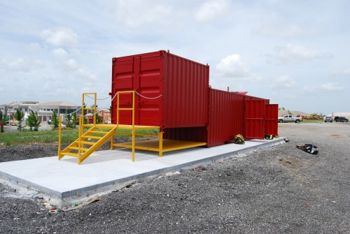
Note: The prop illustrated above is a Split level cell at the Palm Beach County Fire Training Center.

Container based props can be configured in a variety of ways for both demonstration and fire attack training. Most commonly single compartment cells are single level or split level design. Multiple compartment cells are arranged in a variety of ways with containers placed in an “L”, “H” or other configuration.

Do you currently teach firefighters that “Penciling control techniques can be used to give firefighters additional time to escape a flashover”?

We define penciling as an intermittent application using a straight stream as compared to pulsing which uses a fog pattern or painting which is a gentle application of water to hot surfaces. We do not teach penciling, pulsing, or painting as a technique to give firefighters additional time to escape flashover. We use gas cooling (short or long pulses) and coordination of fire attack and ventilation to control the environment and prevent or reduce the potential for firefighters to encounter flashover. However, long pulses (or continuous application) while withdrawing is taught as a method of self-protection if fire conditions exceed the capability of the crew engaged in fire attack.

In response to Casey’s questions, Jim Hester, with the United States Air Force (USAF) presents an alternative perspective:

No! We do not teach penciling or 3D Fog attack anymore. We did temporarily after receiving our training as instructors in the flashover trainer. We gave the technique an honest look and conducted research using Paul Grimwood’s theories. We decided there are too many variables. For example; what works in a room and contents [fire] will not work in heavy fire conditions inside a commercial. The last thing we want is someone penciling any fire, inside any structure, that requires constant water application until the fire is darkened down. That’s what we teach.  Open the nozzle for as long as it takes to get knock down and then shut the nozzle down. [It is as] simple as that. If you take that approach, even in the flashover trainer you will alleviate confusion or misapplication of your fire stream.

While I have a considerably different perspective, Jim raises several good points. I agree that there are many variables related to fire conditions and room geometry. If firefighters are trained in lock step manner that short pulses are used to control the temperature overhead, there will definitely be a challenge in transitioning from the container to a residential fire and even more so when confronted with a commercial fire. However, if firefighters are introduced to the container as a laboratory where small fires are used to develop understanding of nozzle technique, rather than a reflection of real world conditions, this presents less of an issue.

As Jim describes, fire conditions requiring constant application in a combination attack with coordinated tactical ventilation, may not be controlled by short pulses. However, when cooling hot smoke on approach to a shielded fire, constant application of water will likely result in over application and less tenable conditions (too much water may not be as bad as too little, but it presents its own problems).

Most firefighters, even those that advocate continuous application, recognize that a small fire in a trash can or smoldering fire in a upholstered chair or bed does not require a high flow rate and can easily be controlled and extinguished with a small amount of water. On the other hand, a fully developed fire in a large commercial compartment cannot be controlled by a low flow handline. To some extent this defines the continuum of offensive fire attack, small fires easily controlled by direct application of a small amount of water and large fires that are difficult to control without high flow handlines (or multiple smaller handlines). There is not a single answer to what is the best application for offensive fire attack. Shielded fires require control of the environment (e.g., cooling of the hot upper layer) to permit approach and application of direct or combination attack. Fires that are not shielded present a simpler challenge as water can be brought to bear on the seat of the fire with less difficulty.

Nozzle operators must be trained to read conditions and select nozzle technique (pulsed application to cool hot gases versus penciling or painting to cool hot surfaces) and fire control methods (gas cooling, direct attack, indirect attack, or combination attack) based on an assessment of both the building and fire conditions.

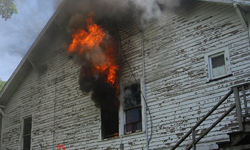
What flashover warning signs do you cover during the classroom portion of flashover training?

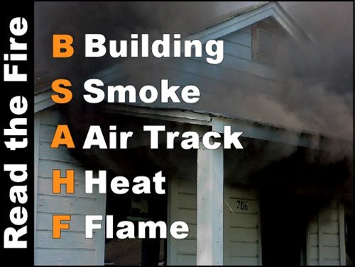
We frame this discussion in terms of the B-SAHF (Building, Smoke, Air Track, Heat, and Flame) indicators used in reading the fire (generally, not just in relation to flashover).

B-SAHF_PHOTO

Building: Flashover can occur in all types of buildings. Consider compartmentation, fuel type, and configuration, ventilation profile, and thermal properties of the structure. Anticipate potential for increased ventilation (without coordinated fire control) to result in flashover when the fire is burning in a ventilation controlled regime (most fires beyond the incipient stage are ventilation controlled). Note that these indicators are not all read during the incident, but are considered as part of knowing the buildings in your response area and assessing the building as part of size-up.

Smoke: Increasing volume, darkening color and thickness (optical density), lowing of the level of the hot gas layer.

Air Track: Strong bi-directional (in at the bottom and out at the top of an opening), turbulent smoke discharge at openings, pulsing air track (may be an indicator of ventilation induced flashover or backdraft), and any air track that shows air movement with increasing velocity and turbulence.

Heat: Pronounced heat signature from the exterior (thermal imager), darkened windows, hot surfaces, hot interior temperatures, observation of pyrolysis, and feeling a rapid increase in temperature while working inside (note that this may not provide sufficient warning in and of itself as it is a late indicator).

Flame: Ignition of gases escaping from the fire compartment, flames at the ceiling level of the compartment, isolated flames in the upper layer (strong indicator of a ventilation controlled fire) and rollover (a late indicator).

How do you incorporate the thermal imaging camera into your flashover class?

We do not teach a “flashover” class. We incorporate learning about flashover (a single fire behavior phenomena) in the context of comprehensive training in practical fire dynamics, fire control, and ventilation (inclusive of tactical ventilation and tactical anti-ventilation). Thermal imagers (TI) are used in a variety of ways beginning with observation of small scale models (live fire), observation of fire development (with and without the TI) and observation of the effects of fire control and ventilation.

Do you allow students to operate the nozzle in the flashover chamber?

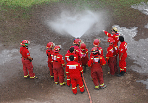
We use a sequence of evolutions and in the first, the students are simply observers watching fire development and to a lesser extent the effects of water application by the instructor. In this evolution, the instructor limits nozzle use and predominantly sets conditions by controlling ventilation. If necessary the instructor will cool the upper layer to prevent flames from extending over the heads of the participants or to reduce the burning rate of the fuel to extend the evolution. Students practice nozzle technique (short and long pulses, painting, and penciling) outside in a non-fire environment prior to application in a live fire context. After the initial demonstration burn, students develop proficiency by practicing their nozzle technique in a live fire context.

When working in a single level cell rather than a split level cell (commonly, but inaccurately referred to as a “flashover chamber” or “flashover simulator”) we expand on development of students proficiency in nozzle technique by having them practice cooling the upper layer while advancing and importantly, while retreating. In addition, students practice door entry procedures that integrate a tactical size-up, door control, and cooling hot gases at the entry point.

Do you maintain two-in/two-out during flashover chamber classes?

We comply with the provisions of NFPA 1403 and provide for two-in/two-out by staffing a Rapid Intervention Crew/Company during all live fire training.

What is your fuel of choice for the 4×8 sheets (OSB, Particleboard or Masonite)?

We have used a variety of fuel types, but commonly use particle board. OSB tends to burn quickly, but can be used if this characteristic is recognized. We have also used a low density fiberboard product (with less glue) which performs reasonably well. The key with fuel is understanding its characteristics and using the minimum quantity of fuel that will provide sufficient context for the training to be conducted. I recommend that instructors conduct test burns (without students) when evaluating fuel packages that will be used in a specific burn building or purpose built prop (such as a demo or attack cell).

Do you have benches or seating in the flashover chamber?

No, firefighters are expected to be in the same position that they would on the fireground, kneeling or in a tripod position. When we work in a demo cell (“flashover chamber”) with benches, we keep the students on the floor.

Do you teach any flashover survival techniques, other than retreat/evacuate?

We focus first on staying out of trouble by controlling the environment. Second, we teach firefighters the skill of retreating while operating the hoseline (generally long pulses to control flames overhead). There are not really any options other than control the fire of leave the environment (quickly)! This is similar to James Hester’s answer of continuous flow, with a sweeping motion (long pulses can be applied in a sweeping manner, particularly in a large compartment). It is important to understand that a short pulse is extremely short (as fast as you can open the nozzle) and a long pulse is anything else (from several seconds to near continuous application, depending on conditions).

Refer to the series of CFBT Blog on Battle Drills for additional discussion developing proficiency in reaction to deteriorating conditions.

Additional Thoughts

Our perspective is that discussion of flashover should be framed in the context of comprehensive fire behavior training, rather than as a “special” topic. Practical fire dynamics must be integrated into all types of structural firefighting training, in particular: Hose Handling, Fire Control, and Tactical Ventilation (but the list goes on). When working with charged hoselines, take the time to practice good nozzle technique as well as moving forward and backward (do not simply stand up and flow water when performing hose evolutions). In fire control training (live fire or not), practice door control, tactical size-up, and door entry procedures. When training on the task activity of tactical ventilation (e.g., taking glass or cutting roof openings), make the decision process explicit and consider the critical elements of coordination and anticipated outcome of you actions.

FDIC

Plan on attending Wind Driven Fires in Private Dwellings at Fire Department Instructors Conference, Indianapolis, IN on Wednesday April 24, 2013 in Wabash 3. Representing Central Whidbey Island Fire & Rescue, Chief Ed Hartin will examine the application of NIST research on wind driven fires to fires in private dwellings. This workshop is a must if the wind blows where you fight fires!

wind_driven_fires_private_dwellings


More Fire Attack Questions

Sunday, March 31st, 2013

san_isidro_nozzle_training

This post continues the discussion with Captain Mike Sullivan with the Mississauga Ontario Fire Department regarding fire attack methods. Captain Sullivan refined his definitions and explanation of direct, indirect, and combination fire attack, stating:

Direct Attack: Water droplets put out the fire (droplets land directly on the burning fuel and cool this fuel to put out the fire).

This is essentially correct, water applied directly to the burning fuel absorb energy as the water is heated and considerably more when vaporized into steam, this reduces the temperature of the fuel and extinguishes the fire. In the end, this is generally necessary regardless of what method of fire attack or fire control you begin with.

Indirect Attack: Steam puts out the fire (water droplets turn to steam and this expanded steam eventually makes its way to the area where the burning fuel is and continues to absorb heat from this burning fuel until the fire goes out. All this steam also reduces oxygen concentration which results in a reduced heat release rate).

This is close, but the process of steam production absorbs a tremendous amount of energy. So it might be more accurate to state that production of steam and that heating of the steam as the hot gases and steam reach a thermal equilibrium cool the fire environment. In addition, steam production reduces oxygen concentration that reduces heat release rate. These processes in combination control and in fewer cases may achieve extinguishment. Indirect attack almost always must be followed up with aggressive overhaul and direct attack to achieve extinguishment. This does not diminish the utility of indirect attack for control of fully developed fires or decay stage fires resulting from limited ventilation (where high temperatures exist).

Combination Attack: Water droplets put out the fire (the droplets act the same way here as in the direct attack).

As with direct attack this is essentially correct. The application of water to burning fuel results in extinguishment through cooling. With the combination attack, some of the water is vaporized in the upper layer, assisting with control of the fire environment as well as the process of extinguishment. However, this is often at the expense of disrupting thermal layering (less of an issue when well-coordinated tactical ventilation is provided in front of fire attack.

This discussion gave rise to several other questions from Captain Sullivan:

In the combination attack, although the hose stream is directed at the ceiling (indirect part of the combination attack) and creates steam it is not as effective at cooling the fuel as the direct part of the combination attack is (wow is that wordy), Therefore,the main purpose of the indirect part of the combination attack is to cool the overhead gases so the entire environment is cooler when firefighters enter and really doesn’t have much to do with extinguishing the fire. So would you say in this case the “indirect” part of the combination attack really isn’t a key contributor to extinguishment?

This would depend (another way of saying “it depends”). The indirect component of the combination attack is important in controlling flaming combustion in the upper layer (such as rollover). While control of the burning gases overhead alone will not achieve extinguishment (same as with gas cooling), it is an important component of the extinguishment process as the heat flux from burning gases overhead is significant both as a threat to firefighters and also as a mechanism for heating unignited fuel and continuing the combustion process of fuel that is already burning. However, in the end, it is the direct element of the combination attack that achieves extinguishment. As with indirect attack, combination attack is followed up with direct attack to achieve complete extinguishment.

If what I have said above is true then, although both the indirect and combination attack produce large amounts of steam, is the purpose of the steam production actually different (put out the fire vs. cool the overhead gases)?

The purpose of steam production in both cases is to take advantage of the high latent heat of vaporization of water to achieve cooling. In addition, indirect attack reinforces the cooling effects of steam production by reducing oxygen concentration and thus reducing heat release rate from the fire.

In his comments Stefan Svensson stated that “in order to put out the fire we need to hit it with water”, but from what we have discussed here, with an indirect attack it is not water putting out the fire but steam.

In the indirect attack, production of steam and related effects on oxygen concentration result in fire control, but not necessarily extinguishment. Consider the potential outcome if you used an indirect attack on a fire in a building an did not follow up with direct attack and thorough overhaul. Likely a return visit to the same building some time later for a rekindle. In the end, when dealing with Class A fuels typically found in buildings, it is necessary to put water on fuel that is burning.

When Nelson and Royer were doing their research on the Iowa Rate of Flow, did they use a combination attack or did they use and indirect attack and then develop the combination attack after their experiments?

The combination attack was developed during their experiments. Initial application of water was done using an indirect attack (similar to that described by Lloyd Layman in Attacking an Extinguishing Interior Fires (1955). The Iowa State Story: The Iowa Rate of Flow Formula and Other Contributions of Floyd W. (Bill) Nelson and Keith Royer to the Fire Service – 1951 to 1988 (Wiesman, J., 1998) provides an excellent overview of Nelson’s and Royer’s work (but their discussion of fire behavior is inconsistent with current theory and terminology). While out of print it is available (used) through Amazon and a number of other used book outlets.

There are many departments that will flow a straight steam ahead of them across the ceiling to cool the room as they make their way to the fire. I have read that this would be considered surface cooling and not gas cooling because a straight stream will pass right through the gas layer without cooling it and only cool the ceiling, upper wall and floor surfaces as the stream bounces off the ceiling and land on the floor. I have a few questions about this.

When straight stream from a combination nozzle or a stream from a solid bore nozzle deflects off the ceiling, does the stream get broken up enough that the droplets become reduced in size enough that they will cool the hot gas layer on the way down to the floor or are they still too large and therefore pass right through the hot gas layer without cooling it?

There is some cooling, but it is less efficient than when a fog pattern is used as the large droplets will be more difficult to vaporize. If temperature is extremely high, some cooling will occur as even large droplets may be vaporized. If the stream can reach the seat of the fire, this inefficiency may be less significant as the fire will likely be controlled by the direct element of the combination attack. When faced with hot gases or flaming combustion overhead with a fire that is shielded from direct attack, cooling the gases with pulsed water fog will be considerably more effective and efficient than use of a solid or straight stream.

When the stream cools the ceiling and upper walls are the ceiling and walls now able to absorb more heat from the upper gas layer ( so this actually would be gas cooling) and if so how effective is it at cooling these gases (how much heat can these cooled surfaces now absorb from the hot gas layer)?

As discussed in my last post, gypsum board (a typical compartment lining material) which has a specific heat of 1.017 kJ/kg (Manzello, Park, Mizukami, & Bentz, 2008). This is one quarter the specific heat of water and half the specific heat of steam. So the indirect cooling effect of removing energy from compartment linings is quite inefficient at cooling the fire environment.

Once you have created steam from applying water to the ceiling and upper walls—-does that steam not now effectively cool the gases? I know you need smaller droplets suspended in the gases to absorb heat from the upper gas layer and steam would certainly meet that criteria.

The specific heat of steam is 2.0 kJ/kg  as compared to the combined theoretical cooling capacity of 2.6 MJ/kg when water is heated from 20o C to 100o C and vaporized into steam. While steam will cool the hot gases until they reach thermal equilibrium, but to a lesser extent than water fog applied into the hot upper layer.

Stefan Svensson mentioned in his comments that “sometimes fog nozzles are the best way to apply water to fire and sometimes it’s straight streams”. You often hear blanket statements being made about straight streams producing less steam and only fog streams can cool the gas layer. I was wondering if you could expand on the misconceptions and highlight some of the better practices we need to know about using the different streams from a more scientific point of view? When approaching a fire are we better to use both straight and fog patterns to cool the room as we make our way to find the base of the fire?

In a conversation with John Wiseman, Keith Royer stated that “there is not just one tool that will solve all fire problems”. The perspective that there is only one way to approach structural firefighting is dogmatic. Dogma is a point of view or tenet put forth as authoritative without adequate grounds. The simplest answer to your question is that when cooling gases, a fog pattern is more effective and when applying water to surfaces, the pattern selected may depend on the distance from the surface. When far away and the stream must be applied through a hot atmosphere, a solid or straight stream will likely be most effective, when close, a straight stream or fog pattern may be equally effective.

A question unrelated to this discussion but I am sure you can help me with. I am sure you are quite aware (or involved with) that excellent video called “kill the flashover” that shows the effects of closing a door. I know that the temperature stops increasing due to the lack of oxygen for heat release. But,  not only does the temperature not increase but it actually quickly decreases. This decrease is due to the fact that the walls and ceiling are absorbing the heat causing it to drastically reduce so my question is this; if that fire was allowed to burn for long enough that the walls could no longer hold any more heat, then the door was closed, would the temperature drop have been less and would it have lowered more slowly?

The reason the temperature dropped so quickly was not due to the absorption of energy by compartment linings, but by reduction of heat release rate (HRR) due to consumption of oxygen within the compartment. So, it would not make a significant difference if the fire had been burning longer. The higher the HRR, the more quickly you would see an impact. This also influences the visible fire behavior indicators (smoke and air track) on the exterior. As demonstrated in the UL ventilation experiments and previous work by NIST, visible smoke and air track indicators decrease dramatically as the fire becomes ventilation controlled due to a reduction in temperature (and resulting reduction in pressure inside the building).

Thanks for the great questions, let’s keep the discussion going! The next set of questions comes from Garland TX regarding “Flashover Training”. A bit of controversy here in a number of areas!

References

Layman, L. (1955) Attacking and extinguishing interior fires. Boston: National Fire Protection Association (NFPA).

Wiesman, J. (1998).The Iowa state story: The Iowa rate of flow formula and other contributions of Floyd W. (Bill) Nelson and Keith Royer to the fire Service – 1951 to 1988. Stillwater, OK: Fire Protection Publications.

Fire Attack Methods: A Few Questions

Saturday, March 23rd, 2013

As I was beginning work on a post focusing on fire attack methods and fire stream effectiveness, I received an e-mail from Captain Mike Sullivan with the Mississauga Ontario Fire Department asking for help in clarifying indirect and combination fire attack methods and their impact on the fire environment.

fire attack questions

Mike is particularly interested in how to explain the method of extinguishment in the various methods of fire attack discussed in the International Fire Service Training Association (IFSTA) Essentials of Firefighting.

As Mike’s current perspectives and explanation of the methods of fire attack are quite good, they serve as a good starting point for our examination of this topic:

 Direct Attack: This is fairly straight forward; water is applied directly to the burning fuel to cool it to the point where there is no longer pyrolysis (below its ignition temperature).

 As Mike explains, the concept and mechanism of direct attack application of water to burning fuel to cool it. However, it is important to remember that combustion does not necessarily cease when flaming combustion is no longer visible, surface combustion can continue unless sufficient cooling is accomplished to not only extinguish flaming and surface combustion, but also to cool the fuel to the point where it is no longer pyrolizing.

 Indirect Attack: Here is how I would like to explain it. This is used when the seat of the fire cannot be readily accessed. Water is applied from the exterior of a very hot compartment (1000 degrees [F]+ at the ceiling) with limited ventilation. The goal is to create as much steam as possible. To do so you can begin with a fog stream since it is the most effective at cooling therefore creates more steam. The fog stream should be directed at the ceiling where it is hottest. Due to the fact that the stream has limited reach you will then want to narrow your stream eventually using straight stream. The idea is to reach as much of the room as possible. When a straight stream hits the superheated walls and ceilings it will also create a huge amount of steam as it cools the surfaces (most people don’t consider that a straight stream can create a lot of steam). The goal is to do this very quickly then close the door or window and let the steam do its work. There is one main question I was hoping you could help me with here since I have read different theories. What is the main mechanism of extinguishment here, does the steam continue to absorb heat to cool the room down and extinguish the fire or is there so much steam created that it excludes the oxygen therefore smothering and not cooling the fire (I realize both are actually happening), basically does this technique mainly cool or smother the fire.

 This is a complex question in need of a simple answer. The simplest answer is that the primary method of extinguishment is cooling. The complexity is in that the cooling is accomplished by several mechanisms. First, water heated from 20o C to 100o C and vaporized into steam absorbs a tremendous amount of energy based on its specific heat (energy required to raise the temperature of a specific mass of water by one degree) and latent heat of vaporization (energy required to change a substance from liquid to gas phase with no increase in temperature).

Water has a specific heat of 4.2 kJ/kg and a latent heat of vaporization of 2260 kJ/kg. Heating a single kilogram of water from 20o C to 100o C and vaporized it into steam, requires 2.6 MJ of energy. In addition (and contrary to common belief in the fire service) steam produced in an environment above 100o C continues to absorb energy and increase in temperature until the temperature of the steam and the surrounding environment is equalized. Steam has a specific heat of 2.0 kJ/kg. This compares to the specific heat of smoke of approximately 1.0 kJ/kg (Särdqvist, 2002) and gypsum board (a typical compartment lining material) which has a specific heat of 1.017 kJ/kg (Manzello, Park, Mizukami, & Bentz, 2008). Water converted to steam in an indirect attack absorbs a tremendous amount of energy and the steam continues to absorb energy as the temperature in the compartment moves towards equilibrium. As with gas cooling or direct attack, some of the water is vaporized in the hot upper layer and some is vaporized in contact with hot surfaces (compartment linings, burning fuel, etc.). As the specific heat of smoke and compartment lining materials are lower than the specific heat of water (as a liquid or steam) and considerably lower than the latent heat of vaporization of water, the temperature of the smoke and compartment linings will drop to a greater extent than the temperature of the steam will increase (for a more detailed discussion of the cooling effects of water along with a bit of math, see Gas Cooling Parts 1-5).

Steam produced in and enclosed space also reduces oxygen concentration. As oxygen is required for release of energy from fuel, this can also be considered an extinguishing method. Reduction in oxygen concentration results in decreased heat release rate (HRR), which correspondingly results in a decrease in temperature. So in reality it is all about cooling (largely accomplished by vaporization of water into steam along with reduction of oxygen concentration).

 Combination Attack: We seem to have a real problem with this one. When I ask for an explanation of this technique I usually get “T”, “O”, and “Z” pattern as an answer. As a matter of fact a neighbouring fire department has these 3 letters painted on their walls to practice the pattern, again we are dealing more with technique instead of method of extinguishment. My explanation is that these patterns are merely a way of creating steam by cooling all surfaces in the room as well as allowing the water land on the burning fuel to cool it. What is the main mechanism of extinguishment here is it the creation of steam (and again what is the steam doing, cooling or smothering) or is it the water on the fuel cooling it. Also, would you recommend using a fog stream to create steam as it cools the gases and nearby surfaces then switch to a straight stream to create steam as it hits more distant surfaces (walls ceilings).

 The combination attack is intended to both cool the hot upper layer and apply water to burning fuel (less so to cool compartment linings, although this is accomplished as well). The term “combination” refers to the combination of direct and indirect attack. As indirect attack is not applied in an occupied compartment due to steam production (on contact with compartment linings), it is critical ventilation be provided in front of and closely coordinated with fire attack. As with the other methods of fire attack, the principle method is cooling.

As to your second question regarding use of a fog stream to create steam as it cools the gases and nearby surfaces and then switch to a straight stream to cool more distance surfaces. A combination attack may be done with a narrow fog pattern, straight stream, or solid stream. Reach in this case is a good thing. Cooling of hot gases overhead (with a little cooling of compartment linings) is the basic concept used in gas cooling. This technique is most commonly used to control the fire environment when the fire is shielded from direct attack and is not an extinguishing method. This approach does not result in an increased volume of steam and smoke and related lowering of the upper layer. In fact if approximately 35% or more of the water is vaporized in the upper layer, the total volume will be reduced (see Gas Cooling Parts 1-5 for a more detailed explanation of why). This technique can be effectively combined with direct attack on burning fuel and painting of compartment linings to lower their temperature. Painting is a gentle application of water to cool without excess steam production.

I believe that the Fire Streams and Fire Control Chapters in the 6th Edition of the International Fire Service Training Association (IFSTA) Essentials of Firefighting provide a more clear discussion of fire attack methods inclusive of direct, indirect, combination, and the technique of gas cooling.

References

International Fire Service Training Association (IFSTA). (2013). Essentials of firefighting (6th ed). Stillwater, OK: Fire Protection Publications.

Manzello, S., Park¸S, Mizukami, T., & Bentz, D. (2008) Measurement of thermal properties of gypsum board at elevated temperatures. Retrieved March 23, 2013 from http://fire.nist.gov/bfrlpubs/fire08/PDF/f08023.pdf

Särdqvist, S. (2002) Water and other extinguishing agents. Karlstad, Sweden: Räddnings Verket

Upcoming Events

April 19-20, 2013 – Seminar and Workshop on Practical Fire Dynamics & 3D Firefighting in Winkler, MB

April 23-27, 2013 – Wind Driven Fires in Private Dwellings at Fire Department Instructors Conference, Indianapolis, IN

May 25-26, 2013 – Compartment Fire Behavior Training Workshop at the British Columbia Training Officers Conference, Penticton, BC


Influence of Ventilation in Residential Structures: Tactical Implications Part 4

Sunday, August 14th, 2011

The fourth tactical implication identified in the Underwriters Laboratories study of the Impact of Ventilation on Fire Behavior in Legacy and Contemporary Residential Construction (Kerber, 2011) is that fire attack and (tactical) ventilation must be coordinated. This recommendation has been repeated in National Institute for Occupational Safety and Health (NIOSH) Death in the Line of Duty Reports for many years. In fact, most reports on firefighter fatalities related to rapid fire progression contain this recommendation.

Importance of Coordination

Coordination of (tactical) ventilation and fire attack as a tactical implication is closely related to the first two tactical implications identified in the UL study; potential changes in fire behavior based on stages of fire development, burning regime, and changes in ventilation profile that increase oxygen supplied to the fire.

If air is added to the fire and water is not applied in the appropriate time frame the fire gets larger and the hazards to firefighters increase. Examining the times to untenability provides the best case scenario of how coordinated the attack needs to be. Taking the average time for every experiment from the time of ventilation to the time of the onset of firefighter untenability conditions yields 100 seconds for the one-story house and 200 seconds for the two-story house. In many of the experiments from the onset of firefighter untenability until flashover was less than 10 seconds. These times should be treated as very conservative. If a vent location already exists because the homeowner left a window or door open then the fire is going to respond faster to additional ventilation openings because the temperatures in the house are going to be higher at the time of the additional openings (Kerber, 2011, p. 289-290)

The Impact of Ventilation on Fire Behavior in Legacy and Contemporary Residential Construction Underwriters Laboratories (UL) on-line course and report provide an example of firefighters are at risk when ventilation is performed prior to entry, fire attack is delayed, and other tactical operations such as primary search are initiated.

In UL’s hypothetical example, the firefighters make entry into the one-story house, search the living room (fire compartment), the kitchen, and dining room shortly after forcing the door and ventilating a large window in the fire compartment. Consider a somewhat different scenario, with the same fire conditions.

Companies respond to a residential fire with persons reported during the early morning hours. A truck and engine arrive almost simultaneously and while the engine lays a supply line from a nearby hydrant, the truck company forces entry, ventilates a window on Side A, and begins primary search (anticipating that the engine crew will be right behind them to attack the fire). The engine completes a forward lay and begins to stretch an attack line after the search team has made entry.

Figure 1. Timeline and Progression of Primary Search

Figure 2. View of the Living Room (Fire Compartment) from the Door on Side A

As illustrated in Figure 3, visible flaming combustion when the door is opened at 08:00 is limited to a small flame from the top of the couch just inside the door on Side A. However, in the 30 seconds that it takes for the search team to make entry, flaming combustion has resumed and flames are near or at the ceiling above the couch. The search team may estimate that they have time to complete a quick search of the bedrooms (likely location of the reported persons). However, fire development progresses to untenable conditions within a minute, trapping the crew on Side D of the house.

Figure 3. Fire Progression in the Living Room 00:08:00 to 00:10:00

As the search team completes primary search of Bedroom 2 and moves towards Bedroom 3 in the hallway, conditions have deteriorated to an untenable level. Figure 4 illustrates the change in temperature at the 3’ level in the Living Room (fire compartment). Shortly before the search team reached Bedroom 2, fire conditions in the living room began to change dramatically, with temperature at the 3’ level transitioning from ordinary to extreme, quickly becoming untenable in the living room, hallway and adjacent compartments. In addition to this significant change in temperature, flames (with temperatures higher than the gas temperature at the 3’ level) significantly increase radiant heat transfer (flux) to the surface of both fuel packages and firefighters protective equipment.

Figure 4. Temperature at the 3’ Level

Note: Figure 4 illustrates temperature conditions starting eight minutes after ignition. The fire previously progressed through incipient and growth stages before beginning to decay due to lack of ventilation.

Why the Dramatic Change in Conditions?

As discussed in UL Tactical Implications Part 1, Fires in the contemporary environment progress from ignition and incipient stage to growth, but often become ventilation controlled and begin to decay, rather than continuing to grow into a fully developed fire. This ventilation induced decay continues until the ventilation profile changes (e.g., window failure due to fire effects, opening a door for entry or egress, or intentional creation of ventilation openings by firefighters. When ventilation is increased, heat release rate again rises and temperature climbs with the fire potentially transitioning through flashover to the fully developed stage (see Figure 4 and 5).

Figure 5. Fire Development in a Compartment

Captain James Mendoza of the San Jose (CA) Fire Department and CFBT-US Lead Instructor demonstrates the influence of ventilation on fire development using a small scale prop developed by Dr. Stefan Svensson of the Swedish Civil Contingencies Agency.

The prop used in this demonstration is a small, single compartment with a limited ventilation opening on the right side (which in a full size building could be represented by normal building leakage or a compartment opening that is restricted such as a partially open door or window). The front wall of the prop is ceramic glass to permit direct observation of fire conditions within the compartment.

As you watch this demonstration, pay particular attention to how conditions change as the fire develops and then enters the decay stage. In addition, observe how quickly the fire returns to the growth stage and develops conditions that would be untenable after the window is opened at 12:17.

Download Doll’s House Plans (or Doll’s House Plans: Metric) for directions on how to construct a similar small scale prop.

Fire development and changes in conditions following ventilation in this demonstration mirror those seen in the full scale experiments conducted by UL. Increasing ventilation to a ventilation controlled fire, results in increased heat release rate and transition from decay to the growth stage of fire development.

The same phenomena can be observed under fireground conditions in the following video clip of a residential fire in Dolton, Illinois (this is a long video, watch the first several minutes to observe the changes in fire behavior).

It appears that the front door was open at the start of the video clip and the large picture window on Side A was ventilated at approximately 00:47. Fire conditions quickly transition to the growth stage with flames exiting the window and door, causing firefighters on an uncharged hoseline that had been advanced into Floor 1, to quickly withdraw.

As discussed in UL Tactical Implications: Part 1:

  • Fires that have progressed beyond the incipient stage are likely to be ventilation controlled when the fire department arrives.
  • Ventilation controlled fires may be in the growth, decay, or fully developed stage.
  • Regardless of the stage of fire development, when a fire is ventilation controlled, increased ventilation will always result in increased HRR.
  • Firefighters and fire officers must recognize that the ventilation profile can change (e.g., increasing ventilation) as a result of tactical action or fire effects on the building (e.g., window failure).
  • Firefighters and fire officers must anticipate potential changes in fire behavior related to changes in the ventilation profile and ensure that fire attack and ventilation are closely coordinated.

Coordinated Tactical Operations

Understanding how fire behavior can be influenced by changes in ventilation is essential. But how can firefighters put this knowledge to use on the fireground and what exactly does coordination of tactical ventilation and fire attack really mean?

Tactical ventilation can be defined as the planned, systematic, and coordinated removal of hot smoke and fire gases and their replacement with fresh air. Each of the elements of this definition is important to safe and effective tactical operations.

Ventilation (both tactical and unplanned) not only removes hot smoke, but it also introduces fresh air which can have a significant effect on fire behavior.

Tactical ventilation must be planned; these two elements speak to the intentional nature of tactical ventilation. Tactics to change the ventilation profile must be intended to influence the fire environment or fire behavior in some way (e.g., raise the level of the upper layer to increase visibility and tenability). The ventilation plan must also consider the flow path (e.g., vent ahead of, not behind, the attack team; vent in the immediate area of the fire, not at a remote location).

Tactical ventilation must be systematic, exhaust openings should generally be made before inlet openings (particularly when working with positive pressure ventilation or when taking advantage of wind effects).

And as pointed out in the UL Study (Kerber, 2011), tactical ventilation must be coordinated. Coordination of ventilation and other tactical operations requires consideration of sequence and timing:

Sequence: Ventilation may be completed before, during, or after fire attack has been initiated. Sequence will likely depend on the stage of fire development, burning regime, time required to reach the fire.

If the fire is small and staffing is limited, it may be appropriate to control the fire and then effect ventilation (e.g., hydraulic ventilation performed by the attack team). This approach minimizes potential fire growth,

In general, when the fire is ventilation controlled (as those beyond the incipient stage are likely to be), ventilation should not be completed unless the attack line(s) can quickly apply water to the seat of the fire. In a small, single family dwelling this may mean that the attack team is on-air, the line is charged, and the entry door is unlocked or has been forced and is being controlled (held closed). In a larger building, this may mean that the attack line has entered the structure and is in position to move onto the fire floor or into the fire area.

The key questions that must be answered prior to implementing tactical ventilation are:

  1. What influence will these ventilation tactics have on fire behavior?
  2. Are charged and staffed attack line(s) in place?
  3. Will the attack team(s) be able to quickly reach the fire?
  4. How will this impact crews operating on the interior of the building?

Coordination requires clear, direct communication between companies or crews assigned to ventilation, fire attack, and other tactical functions that are or will be taking place inside the building.

Important: While not a tactical implication directly raised by the UL study, another important consideration is the hazard of working without or ahead of the hoseline. While a controversial topic in the US fire service (where truck company personnel generally work on the interior without a hoseline), searching with a hoseline provides a means of protection and a defined exit path. Staffing is another key element of the operational context. If you do not have enough personnel to control the fire and search; in most cases it is likely the best course of action to control the fire and ensure a safer operating environment for search operations.

What’s Next?

The next tactical implication identified in the UL study (Kerber, 2011) examines information that may be obtained by reading the air track at the entry point opening. This implication will be expanded with a broader discussion of air track indicators and how related hazards can be mitigated to improve firefighter safety.

References

Kerber, S. (2011). Impact of ventilation on fire behavior in legacy and contemporary residential construction. Retrieved July 16, 2011 from http://www.ul.com/global/documents/offerings/industries/buildingmaterials/fireservice/ventilation/DHS%202008%20Grant%20Report%20Final.pdf


Note: Figure 4 illustrates temperature conditions starting eight minutes after ignition. The fire previously progressed through incipient and growth stages before beginning to decay due to lack of ventilation.

Why the Dramatic Change in Conditions?

As discussed in UL Tactical Implications Part 1 [LINK], Fires in the contemporary environment progress from ignition and incipient stage to growth, but often become ventilation controlled and begin to decay, rather than continuing to grow into a fully developed fire. This ventilation induced decay continues until the ventilation profile changes (e.g., window failure due to fire effects, opening a door for entry or egress, or intentional creation of ventilation openings by firefighters. When ventilation is increased, heat release rate again rises and temperature climbs with the fire potentially transitioning through flashover to the fully developed stage (see Figure 4 and 5).

Figure 5. Fire Development in a Compartment

Safe & Effective Live Fire Training or Near Miss?

Monday, July 4th, 2011

A recent video posted on the firevideo.net [http://firecamera.net/] web brought to mind a number of painful lessons learned regarding live fire training in acquired structures. When watching video of fire training or emergency incidents, it is essential to remember that video provides only one view of the events. This video, titled Probationary Live House Burn shows a live fire evolution from ignition through fire attack with the comment “Burnin up the probies… LOL”.

This video shows multiple fire locations and an extremely substantial fire load (well in excess of what is necessary to bring typical residential compartments to flashover). I am uncertain if the comment posted with the video “burnin up the probies…LOL [laughing out loud]” was posted by an instructor or learner. Likely this is considered as just a joke, but comments like this point to our collective cultural challenges in providing safe and effective live fire training.

Fuel Load & Ventilation in Live Fire Training

NFPA 1403 Standard on Live Fire Training is reasonably explicit regarding the nature of acceptable fuel, extent of fuel load, as well as number and location of fires used for live fire training in acquired structures.

4.3.1 The fuels that are utilized in live fire training evolutions shall have known burning characteristics that are as controllable as possible.

4.2.17 Combustible materials, other than those intended for the live fire training evolution, shall be removed or stored in a protected area to preclude accidental ignition.

4.3.3* Pressure-treated wood, rubber, and plastic, and straw or hay treated with pesticides or harmful chemicals shall not be used.

A.4.3.3 Acceptable Class A materials include pine excelsior, wooden pallets, straw, hay, and other ordinary combustibles.

Fuel materials shall be used only in the amounts necessary to create the desired fire size.

A.4.3.4 An excessive fuel load can contribute to conditions that create unusually dangerous fire behavior. This can jeopardize structural stability, egress, and the safety of participants.

4.3.5 The fuel load shall be limited to avoid conditions that could cause an uncontrolled flashover or backdraft.

4.4.15 Only one fire at a time shall be permitted within an acquired structure.

4.4.16 Fires shall not be located in any designated exit paths.

While quite explicit regarding fuel requirements and limitations, NFPA 1403 (2007) has little to say about the ventilation with the exception of a brief mention that roof ventilation openings that are normally closed but may be opened in an emergency are permitted (not required as many believe). However, the Appendix has a much more important statement regarding the importance of ventilation to fire development:

A.4.3.7 The instructor-in-charge is concerned with the safety of participants and the assessment of conditions that can lead to rapid, uncontrolled burning, commonly referred to as flashover. Flashover can trap, injure, and kill fire fighters. Conditions known to be variables affecting the attainment of flashover are as follows:

(1) The heat release characteristics of materials used as primary fuels

(2) The preheating of combustibles

(3) The combustibility of wall and ceiling materials

(4) The room geometry (e.g., ceiling height, openings to rooms [emphasis added])

In addition, the arrangement of the initial materials to be ignited, particularly the proximity to walls and ceilings, and the ventilation openings [emphasis added] are important factors to be considered when assessing the potential fire growth.

The building in this video appeared to have been used for multiple evolutions prior to the one depicted in the video. A number of the windows appeared to be damaged, providing increased ventilation to support combustion. The fuel load of multiple pallets and excelsior or straw (acceptable types of fuel) provided an excess of fuel required to reach flashover in typical residential rooms (which may have been an intended outcome and level of involvement given the transitional attack (defense to offense)). If in fact the sets were in multiple rooms, this would be inconsistent with the provisions of NFPA 1403 limiting acquired structure evolutions to a single fire.

It is essential for those of us who conduct live fire training to remember that most of the provisions of NFPA 1403 (2007) are based on line-of-duty deaths of our brothers and sisters. Safe and effective live fire training requires that instructors be technically competent, well versed in the requirements or relevant regulations and standards, and that individually and organizationally we have an appropriate attitude towards safe and effective learning and the process of passing on the craft of firefighting.

One useful case to focus discussion of these issues is the death of Firefighter/Paramedic Apprentice Rachael Wilson of the Baltimore City Fire Department:

Live Fire Training: Remember Rachael Wilson

Live Fire Training Part 2: Remember Rachael Wilson

NIOSH Death in the Line of Duty F2007-09

Independent Investigation Report: Baltimore City Fire Department Live Fire Training Exercise

Door Entry

At 4:56 in the video, accumulation of a layer of smoke is clearly visible under the porch roof. No comment is made about this by the instructors and no action is taken to mitigate the hazard. At 5:55, flames exiting a broken window to the left of the door ignite the smoke layer just prior to when the attack team opens the door.

Figure 1. Fire Gas Ignition Sequence

It is essential to recognize that smoke is fuel and that ignition of this gas phase fuel overhead results in a rapid and signfiicant increase in radiant heat flux (which is dependent largely on temperature and proximity). Cooling the gases overhead and use of good door entry technique can minimize risk of this thermal insult to firefighters and potential for transition to other types of extreme fire behavior such as flashover.

Fire Streams

This video also shows some interesting aspects of fire stream application. A solid (or straight) stream can be quite effective in making a direct attack on the fire. However, when the fire is shielded, the effectiveness of this type of stream is limited. While limited steam production is often cited as an advantage of solid (and straight) streams, initial application of water through the doorway in this video results in significant steam production and limited effect on the fire. This is likely due to shielding of the burning fuel by interior configuration and compartmentation. Remember than no single type of fire stream is effective for all applications.

Perspective

Consider the question posed in the title of this post: Was this a safe and effective live fire training session or a near miss? I suspect that the learners in the video enjoyed this live fire training session and that the instructors desired to provide a quality learning experience. It is even likely that this evolution was conducted substantively (but likely not completely) in compliance with the provisions of NFPA 1403. Like most training exercises and emergency incidents, it is easy to watch a video and criticize the actions of those involved. I do not question the intent of those involved in this training exercise, but point to some issues that we (all of us) need to consider and reflect on as we go about our work and pass on the craft to subsequent generations of firefighters.

What’s Next?

I am working hard at getting back into a regular rhythm of posting and hope to have a post looking at another of the Tactical Considerations from the UL ventilation study up within the next week.

Ed Hartin, MS, EFO, MIFireE, CFO

References

National Fire Protection Association. (2007). NFPA 1403 Standard on live fire training. Quincy, MA: Author.

National Institute for Occupational Safety and Health (NIOSH). (2002). Death in the line of duty, F2007-09. Retrieved February 19, 2009 from http://www.cdc.gov/niosh/fire/pdfs/face200709.pdf

Shimer, R. (2007) Independent investigation report: Baltimore city fire department live fire training exercise 145 South Calverton Road February 9, 2007. Retrieved February 19, 2009 from http://www.firefighterclosecalls.com/pdf/BaltimoreTrainingLODDFinalReport82307.pdf.

Influence of Ventilation in Residential Structures: Tactical Implications Part 2

Saturday, June 18th, 2011

Is making entry with a hoseline for fire attack, ventilation? Is entering through a doorway when conducting search, ventilation? While many firefighters do not think about ventilation when performing these basic fireground tasks, the answer is a resounding yes!

Making Entry is Ventilation

While the Essentials of Firefighting (IFSTA, 2008) defines ventilation as “the systematic removal of heated air, smoke, and fire gases from a burning building and replacing them with cooler air” [emphasis added] (p. 541), the main focus of most ventilation training is on the exhaust opening. In discussing compartment fire development, the 6th Edition of Essentials (IFSTA, 2008) includes a discussion of the concept of fuel and ventilation controlled burning regimes. In addition, the section of the text addressing the positive effects of ventilation such as reducing potential for flashover and backdraft, Essentials (IFSTA, 2008) cautions that increasing ventilation to ventilation limited fires may result in rapid fire progression. However, these concepts were not included in earlier additions and the connection between openings made for the purpose of ventilation and openings made for other reasons is often overlooked.

Ventilation versus Tactical Ventilation

Despite the definitions given in fire service text that describe ventilation in terms of actions taken by firefighters, ventilation is simply the exchange of the atmosphere inside a building with that which is outside. Normal air exchange between the interior and exterior of a building is expressed as the number of complete air exchanges (by volume) per hour and varies depending on the purpose and function of the space. In residential structures, the air in the building is completely exchanged approximately four times per hour. In commercial and industrial buildings this rate may be significantly higher, depending on use. When firefighters arrive to find smoke issuing from a building, ventilation is occurring and when firefighters open a door to make entry, the ventilation profile changes as ventilation has been increased. Remember:

  • If smoke exits the opening (air is entering somewhere else) ventilation is occurring.
  • If air enters the opening (smoke is exiting somewhere else), ventilation is occurring.
  • If smoke exits and air enters the opening ventilation is occurring.

The entry point is a ventilation opening and if the fire is ventilation controlled, any ventilation opening will increase heat release rate (HRR)!

Ventilation Controlled Fires

As discussed in Influence of Ventilation in Residential Structures: Tactical Implications Part 1 [LINK], compartment fires that have progressed beyond the incipient stage are likely to be ventilation controlled when the fire department arrives. Firefighters and fire officers must recognize the potential for a rapid increase in HRR when additional atmospheric oxygen is provided to ventilation controlled fires. This is particularly important when considering door entry and door control during fire attack, search, and other interior operations. The Underwriters Laboratories (UL) research project Impact of Ventilation on Fire Behavior in Legacy and Contemporary Residential Construction (Kerber, 2011) examined fire behavior in a small, single-story, wood frame house and a larger, two-story, wood frame house (see Figures 1 & 2) Figure 1. Single-Story Legacy Dwelling

Figure 2. Two-Story Contemporary Dwelling

Each of the fires in these experiments occurred in the living room (one-story house) or family room (two-story house). While the fuel load was essentially the same, the family room had a much greater volume as it had a common cathedral ceiling with an atrium just inside the front door. Experiments one and two examined fire behavior in each of these structures with the front door being opened at the simulated time of arrival of the fire department. Figure 3 illustrates the changes in temperature during UL Experiment 1 (Single Story-Door as Vent Opening) and Experiment 2 (Two-Story-Door as Vent Opening). Figure 3. Living/Family Room Temperature Curves-Door as Ventilation Opening

As illustrated in Figure 3, temperature conditions changed dramatically and became untenable shortly after the front door was opened. In the one-story experiment (Experiment 1) temperature:

  • Was 180 °C (360 °F) at ventilation (480 s),
  • Exceeded the firefighter tenability threshold of 260 °C (500 °F) at 550 s
  • Reached 600 °C (1110 °F) at 650 s and transitioned through flashover to a fully developed fire in the living room

In the two-story experiment (Experiment 2) temperature:

  • Was 220 °C (430 °F) at ventilation (600 s)
  • Exceeded the firefighter tenability threshold of 260 °C (500 °F) at 680 s
  • Reached 600 °C (1110 °F) at 780 s and transitioned through flashover to a fully developed fire in the family room

When the door is opened the clock is ticking! HRR will increase and the tenability within the fire compartment and adjacent spaces will quickly deteriorate unless water can be applied to control the fire. Keeping the door closed until ready to make entry delays starting the clock. Closing the door after entry (leaving room for passage of your hoseline) slows fire development and buys valuable time to control the fire environment, locate the fire, and achieve fire control.

Just as in the UL experiments on the influence of ventilation in residential structures, heat release rate will increase and fire conditions can change dramatically when a door is opened for access and entry.

In 2008, two firefighters from the Riverdale Volunteer Fire Department in Prince Georges County Maryland recently were surprised by a flashover in a small, single family dwelling. In the first photo, firefighters from Engine 813 and Truck 807 prepare to make entry. Note that the front door is closed, the glass of the slider and windows are darkened, and smoke can be observed in the lower area of the front porch. Six seconds later it appears that the front door has been opened, flames are visible through the sliding glass door, and the volume of smoke in the area of the porch has increased. However, the smoke is not thick (optically dense). Forty eight seconds later, as the crew from Truck 807 makes entry to perform horizontal ventilation the volume of smoke from the front door increases and thickens (becomes more optically dense).

Figure 4. Ventilation Induced Flashover-Door as a Ventilation Opening

Note: Photos by Probationary Firefighter Tony George, PGFD The crew from Engine 813 experienced a burst hoseline, delaying fire attack. Two minutes after the first photo, and shortly after the crew from Truck 807 made entry, flashover occurred. For additional information on this incident, see Situational Awareness is Critical.

Door Control

The issue of door control presents a similar (and related) paradox as ventilation. Ventilation is performed to improve interior tenability and to support fire control, but when presented with a ventilation controlled fire, increased air supply increases HRR and can result in worsening tenability and potential for extreme fire behavior. Firefighters often chock doors open to provide ease of hoseline deployment and an open egress path, but when the fire is ventilation controlled, this (ventilation) opening starts the clock on increased HRR and rapid fire development. It is useful to consider door control in two phases, door entry procedures and control of the door after entry.

Size-Up: Door entry begins with a focused size-up as you approach the building. Assessment of conditions is not only the incident commander or officer’s job. Each member entering the building should perform a personal size-up and predict likely conditions. When making entry, size-up becomes more closely focused on conditions observed at or near the door and includes an assessment of potential forcible entry requirements as well as B-SAHF (Building-Smoke, Air Track, Heat, and Flame) indicators. If available, a thermal imaging camera (TIC) can be useful, but remember that temperature conditions may be masked by the thermal characteristics of the building. If a thermal imaging camera is not available, application of a small amount of water to the door may indicate temperature and the level of the hot gas layer (water will vaporize on contact with a hot door).

Size-up begins as you exit the apparatus and approach the building, but continues at the door and after you make entry!

At the door, pay close attention to air track and heat (door temperature) indicators as these can provide important clues to conditions immediately inside the building!

Prior to Entry: If the door is open, close it. If it is closed, don’t open it until you are ready. If the door is unlocked, control is generally a simple process (see Nozzle Techniques and Hose Handling: Part 3 for detailed discussion of door entry when the door is unlocked).

If the door is locked and must be forced, this adds an element of complexity to the door entry process. In selecting a forcible entry method, consider that the door must remain intact and on its hinges if you are going to maintain control of the air track at the opening.

This is fairly easy with outward opening doors. Inward opening doors present a greater challenge. A section of webbing or rope can be used to control an inward door by placing a cinch hitch around the door knob (see Figure 5). As the the door is forced, it can be pulled closed. However, if the door was not locked with a deadbolt, it may re-latch when pulled closed. Figure 5. Door Control with Web or Utility Rope

Figure 5. Door Control with Webbing or Utility Rope

<

Alternately, a Halligan or hook may be used to capture the door and pull it substantially closed after it is forced (see Figure 6).

Figure 6. Door Control with a Tool

If B-SAHF (Building, Smoke, Air Track, Heat, & Flame) indicators point to hazardous conditions on the other side of the door, forcible entry must be integrated with good door entry procedure to control potential hazards. After Entry: The most effective way to control the door after entry and provide ease of egress is to have a firefighter remain at the opening to control the door and feed hose to the hose team working inside (see Figure 7).

Figure 7. Door Control After Entry

Note: The Firefighter maintaining door control would be wearing complete structural firefighting clothing and breathing apparatus (this is simply an illustration of door control with a hoseline in place)!

Unfortunately, many companies do not have sufficient staff to maintain a nozzle team of two and leave another firefighter at the door. In these cases, it may be possible for the standby firefighters (two-out) to control the door for the crew working inside until additional resources are available.

Nozzle Technique & Hose Handling

Prior posts on nozzle technique and hose handling included a series of drills to develop proficiency in critical skills.

Review these nine drills and then extend your proficiency by integrating forcible entry with good door entry procedure by maintaining control of the door.

Drill 10-Door Entry-Forcing Inward Opening Doors: Many doors (particularly interior and exterior residential) open inward. In this situation forcible entry, door control, and nozzle operation must bee closely coordinated. Practicing these techniques under a variety of conditions (e.g., wall locations, compartment sizes) is critical to developing proficiency.

Drill 11-Door Entry-Forcing Outward Opening Doors: Commercial (and some interior residential doors) open outward. While less complex, Firefighters must develop skill in integration of forcible entry, door control, and nozzle technique in this situation as well.

Hose Handling and Nozzle Technique Drills 11 & 12 Instructional Plan

In both of these drills, focus on maintaining control of the door during forcible entry and limit air intake by keeping the door as closed as possible while passing the hoseline as it is advanced.

References

Kerber, S. (2011). Impact of ventilation on fire behavior in legacy and contemporary residential construction. Retrieved January 20, 2011 http://www.ul.com/global/documents/offerings/industries/buildingmaterials/fireservice/ventilation/DHS%202008%20Grant%20Report%20Final.pdf

International Fire Service Training Association (IFSTA). (2008) Essentials of firefighting (6th ed.). Stillwater, OK: Fire Protection Publications.

Homewood, IL LODD

Saturday, November 13th, 2010

Introduction

While formal learning is an essential part of firefighters’ and fire officers’ professional development, informal learning is equally important, with lessons frequently shared through the use of stores. Stories are about sharing knowledge, not simply about entertainment. It is their ability to share culture, values, vision and ideas that make them so critical. They can be one of the most powerful learning tools available (Ives, 2004). “Only by wrestling with the conditions of the problem at hand and finding his own way out, does [the student] think” (Dewey, 1910, p. 188).

Developing mastery of the craft of firefighting requires experience. However, it is unlikely that we will develop the base of knowledge required simply by responding to incidents. Case studies provide an effective means to build our knowledge base using incidents experienced by others. This case is particularly significant as the circumstances could be encountered by almost any firefighter.

Aim

Firefighters and fire officers recognize and respond appropriately to the hazards of ventilation controlled fires in small, Type V (wood frame), single family dwellings.

References

National Institute for Occupationsl Safey and Health (NIOSH). (2010). Death in the line of duty: Report F2010-10. Retrieved October 22, 2010 from http://www.cdc.gov/niosh/fire/pdfs/face201010.pdf.

Ives, B. (2004) Storytelling and Knowledge Management: Part 2 – The Power of Stories. Retrieved May 6, 2010 from http://billives.typepad.com/portals_and_km/2004/08/storytelling_an_1.html

Dewey, J. (1910) Democracy and education. New York: McMillan

Learning Activity

Review the incident information and discuss the questions provided. Focus your efforts on understanding the interrelated impact of ventilation and fire control tactics on fire behavior. Even more important than understanding what happened in this incident is the ability to apply this knowledge in your own tactical decision-making.

The Case

This case study was developed using NIOSH Death in the Line of Duty: Report F2010-10 (NIOSH, 2010).

On the evening of March 30, 2010, while operating at a fire in a small single family dwelling, Firefighter/Paramedic Brian Carey and Firefighter/Paramedic Kara Kopas were assigned to assist in advancement of a 2-1/2” handline for offensive fire attack and to support primary search. Shortly after entering the building conditions deteriorated and they were trapped by rapid fire progression. Firefighter Kopas suffered 2nd and 3rd degree burns to her lower back, buttocks, and right wrist. Firefighter Carey died from carbon monoxide poisoning and inhalation of smoke and soot. A 84 year old male civilian occupant also perished in the fire.

Figure 1. Side A Post Fire

Side A Post Fire

Note: National Institute for Occupational Safety and Health (NIOSH)

Building Information

This incident involved a 950 ft2 (88.26 m2), one-story, single family dwelling constructed in 1951. The house was of Type V (wood frame) construction with a hip roof covered with asphalt shingles. The roofline of the hip roof provided a small attic space. Sometime after the home was originally constructed an addition C was built that attached the house to a garage located on Side C. Compartment linings were drywall. The house, garage, and addition were all constructed on a concrete slab.

There were several openings between the house and addition, including two doors, and two windows (see Figure 3).

Note: The number and nature of openings between the garage and addition is not reported, but likely included a door and possibly a window (given typical garage construction). NIOSH investigators did not determine if the doors and windows between the house, addition, and garage were open or closed at the time of the fire as they were consumed by the fire and NIOSH did not interview the surviving occupant (S. Wertman, personal communication, November 17, 2010). The existence and position of the door shown in the wall between the addition and garage is speculative (based on typical design features of this type of structure).

Figure 2. Plot Plan and Apparatus Positioning

Figure 3. Floor Plan 17622 Lincoln Avenue

The Fire

Investigators believe that the fire originated in an addition that was constructed between the original home and the two-car garage. The surviving occupant reported that she observed black smoke and flames from underneath the chair that her disabled husband was sitting in.

The addition was furnished as a family room and fuel packages included upholstered furniture and polyurethane padding. The civilian victim also had three medical oxygen bottles (one D Cylinder (425 L) and two M-Cylinders (34 L). It is not know if the oxygen in these cylinders was a factor in fire development. The garage contained a single motor vehicle in the garage and other combustible materials.

After calling 911 and attempting to extinguish the fire, the female occupant exited the building. NIOSH Death in the Line of Duty Report 2010-10 did not specify this occupants egress path or if she left the door through which she exited open or closed (NIOSH did not interview the occupant, she was interviewed by local fire and law enforcement authorities). The NIOSH investigator (personal communications S. Wertman, November 17, 2010) indicated that the occupant likely exited through the exterior door in the addition or through the door on Side A. Give rapid development through flashover in the addition, it is likely that the exterior door in the addition or door to the garage was open, pointing to the likelihood that the occupant exited through this door. Subsequent rapid extension to the garage was likely based on design features of the addition and garage or some type of opening between these two compartments. As similar extension did not occur in the house, it is likely that the door and windows in the Side C wall of the house were closed.

In the four minutes between when the incident was reported (20:55 hours) and arrival of a law enforcement unit (20:59), the fire in the addition had progressed from the incipient stage to fully developed fire conditions in both the addition and garage.

Dispatch Information

At 2055 hours on March 30, 2010, dispatch received a call from a resident at 17622 Lincoln Avenue stating that her paralyzed husband’s chair was on fire and that he was on oxygen. The first alarm assignment consisting of two engines, two trucks, a squad, and ambulance, and fire chief was dispatched at 2057.

Table 1. On-Duty and Additional Unit Staffing of First Alarm Resources

Unit

Staffing

Engine 534 Lieutenant, Firefighter, Engineer
Ambulance 564 2 Firefighter Paramedics
Truck 1220 (Auto Aid Department) Lieutenant, 2 Firefighters, Engineer
Engine 1340 (Auto Aid Department) Lieutenant 3 Firefighters, Engineer
Truck 1145 (Auto Aid Department) Lieutenant, 2 Firefighters, Engineer
Squad 440 (Auto Aid Department) Lieutenant, 3 Firefighters
Chief Chief

Note: This table was developed by integrating data from Death in the Line of Duty Report 2010-10 (NIOSH, 2010).

Weather Conditions

The weather was clear with a temperature of 12o C (53o F). Firefighters operating at the incident stated that wind was not a factor.

Conditions on Arrival

A law enforcement officer arrived prior to fire companies and reported that the house was “fully engulfed” and that the subject in the chair was still in the house.

Truck 1220 (T-1220) arrived at 2101, observed that the fire involved a single family dwelling, and received verbal reports from law enforcement and bystanders that the male occupant was still inside. Note: The disabled male occupant’s last known location was in the addition between the house and garage, but it is unknown if this information was clearly communicated to T-1220 or to Command (E-534 Lieutenant).

Engine 534 (E-534) arrived just behind T-1220 and reported heavy fire showing. E-534 had observed flames from Side C during their response and discussed use of a 2-1/2” (64 mm) handline for initial attack.

Firefighting Operations

Based on the report of a trapped occupant, T-1220B (Firefighter and Apparatus Operator) prepared to gain entry and conduct primary search. Note: Based on data in NIOSH Death in the Line of Duty Report 2010-10, it is not clear that this task was assigned by the initial Incident Commander (Engine 534 Lieutenant). It appears that this assignment may have been made by the T-1220 Lieutenant, or performed simply as a default truck company assignment for offensive operations at a residential fire.

Upon arrival, the E-534 Lieutenant assumed Command and transmitted a size-up report indicating heavy fire showing. The Incident Commander(E-534 Lieutenant) assisted the E-534 Firefighter with removal of the 1-3/4” (45 mm) skid load from the solid stream nozzle on the 2-1/2” (64 mm) hose load and stretching the 2-1/2” (64 mm) handline to the door on Side A. The E-534 Apparatus Operator charged the line with water from the apparatus tank and then hand stretched a 5” supply line to the hydrant at the corner of Lincoln Avenue and Hawthorne Road with the assistance of a Firefighter from T-1220.

Figure 4. Initiation of Primary Search

The Incident Commander (E-534 Lieutenant) assisted T-1220B in forcing the door on Side A. T-1220B made entry without a hoseline and began a left hand search as illustrated in Figure 4, noting that the upper layer was banked down to within approximately 3’ (0.9 m) from the floor).

Arriving immediately after E-534, the crew of A-564 donned their personal protective equipment and reported to the Incident Commander at the door on Side A, where he and the E-534 Firefighter were preparing to make entry with the 2-1/2” hoseline. The Incident Commander then assigned A-564 to work with the E-534 Firefighter to support search operations and control the fire.

T-1220 initiated roof operations and began to cut a ventilation opening on Side A near the center of the roof. Note: Based on data in NIOSH Death in the Line of Duty Report 2010-10, it is not clear that this task was assigned by the initial Incident Commander (Engine 534 Lieutenant). It appears that this assignment may have been made by the T-1220 Lieutenant, or performed simply as a default truck company assignment for offensive operations at a residential fire.

As illustrated in Figure 5, a large body of fire can be observed on Side C and a bi-directional air track is evident at the point of entry on Side A with dark gray smoke pushing from the upper level of the doorway at moderate velocity. All windows on Sides A and B were intact, with evidence of soot and/or condensed pyrolizate on the large picture window adjacent to the door on Side A.

Figure 5. Conditions Viewed from the Alpha/Bravo Corner at Approximately

Note: Warren Skalski Photo from NIOSH Death in the Line of Duty Report F2010-10.

The Firefighter from E-534 took the nozzle and assisted by Firefighters Carey and Kopas (A-564) stretched the 2-1/2” (64 mm) handline through the door on Side A and advanced approximately 12’ (3.66 m) into the kitchen. As they advanced the hoseline, they were passed by T-1220B, conducting primary search. The E-534 Firefighter, Firefighter Kopas (A-564), and T-1220B observed thick (optically dense), black smoke had dropped closer to the floor and that the temperature at floor level was increasing.

Figure 6. Primary Search and Fire Control Crews

Questions

Take a few minutes and consider the answers to the following questions. Remember that it is much easier to sort through the information presented by the incident when you are reading a blog post, than when confronted with a developing fire with persons reported!

  1. What B-SAHF (Building, Smoke, Air Track, Heat, & Flame) indicators were observed during the initial stages of this incident?
  2. What stage(s) of fire and burning regime(s) were present in the building when T-1220 and E-534 arrived? Consider potential differences in conditions in the addition, garage, kitchen, bedrooms, and living room?
  3. What would you anticipate as the likely progression of fire development over the next several minutes? Why?
  4. How might tactical operations (positively or negatively) influence fire development?

Ed Hartin, MS, EFO, MIFireE, CFO

Note: The number and nature of openings between the garage and addition is not reported, but likely included a door and possibly a window (given typical garage construction). NIOSH investigators did not determine if the doors and windows between the house, addition, and garage were open or closed at the time of the fire as they were consumed by the fire and NIOSH did not interview the surviving occupant (S. Wertman, personal communication, November 17, 2010). The existence and position of the door shown in the wall between the addition and garage is speculative (based on typical design features of this type of structure).

Flow Rate and Nozzle Design

Thursday, October 21st, 2010

A number of years ago, several nozzle manufacturers developed a break apart combination nozzle (shutoff separate from the tip) with an integrated solid stream tip. This design allowed the user to adjust the pattern using the combination tip, or if desired, remove the combination tip and use the nozzle to develop a solid stream. Good idea or not? On the surface this sounds like it might be a reasonable idea. The combination tip allows adjustment of the pattern while the internal solid stream may provide improved performance in penetration to reach burning fuel surfaces. In addition, if the combination tip became clogged with debris it is also possible to remove the tip and still have the capability to develop a usable fire stream.

Used on various size handlines, internal solid stream tips are generally available in sizes ranging from 7/8” to 1-1/4”. What effect does an integrated solid stream tip have on nozzle performance when a combination tip is used? Manufacturers such as Elkhart Brass and Task Force Tips warn that the integrated smooth bore tip may restrict the flow of single flow, variable flow, or automatic combination tips.

CWIFR Nozzle Tests

Tests conducted by Firefighter Jim Huff of Central Whidbey Island Fire & Rescue (CWIFR) demonstrate the potential friction loss impact of integrated solid stream tips. CWIFR conducted flow tests using an mid-range Elkhart Phantom tip, a 1-1/2” (38 mm) ball valve, and a 1-1/2” (38 mm) ball valve with an integrated 15/16” (23.8 mm) tip. Line gages were inserted at the base of the nozzle and between the shutoff and the tip. Nozzle inlet pressure was adjusted to maintain the designed nozzle pressure of 100 psi (690 kPa) at the tip and pressure measurements were made at each of the nozzles flow settings of 30, 95, 125, 150, and 200 gpm (114, 360, 473, 658, and 757 lpm).

As illustrated in Figure 1, the ball valve without the integrated tip had limited impact on tip pressure.

Figure 1. Full Flow Ball Valve

However, the results obtained when using a 1-1/2” (38 mm) ball valve with an integrated 15/16” (23.8 mm)solid stream tip were dramatically different. As illustrated in Figure 2, a considerably higher inlet pressure was required to provide the designed operating pressure of 100 psi (690 kPa) at the tip.

Figure 2. Ball Valve with a Solid Stream Tip

When equipped with an integrated solid stream tip, the friction loss in the nozzle shutoff is significantly impacted by tip size (the smaller the tip, the greater the friction loss at a given flow rate).

This is My Nozzle

As stated in My Nozzle:

This is my nozzle, there are many like it but this one is mine. My nozzle is my best friend. It is my life. I must master it as I master my life. Without me it is useless, without my nozzle I am useless.

I will use my nozzle effectively and efficiently to put water where it is needed. I will learn its weaknesses, its strengths, its parts, and its care. I will guard it against damage, keep it clean and ready. This I swear.

It is essential that firefighters, apparatus operators, and fire officers have an in-depth knowledge of their tools. A handline nozzle is your primary firefighting weapon in offensive firefighting operations, develop your nozzle knowledge and master this important tool.

Ed Hartin, MS, EFO, MIFireE, CFO

Gas Cooling: Part 5

Wednesday, October 6th, 2010

This is the last post in the series examining the science of gas cooling as a fire control tactic. Be forewarned, there is math ahead! I have made an attempt at providing sufficient explanation to allow firefighters, fire officers, and instructors to develop an understanding the scientific concepts underlying this fire control technique. My next post will return to the topic of extreme fire behavior and ventilation with discussion of the most recently released NIOSH report, Death in the Line of Duty 2010-10.

The Mathematical Explanation

Dr. Stefan Särdqvist provides a mathematical explanation of volume changes during smoke/gas cooling In Water and Other Extinguishing Agents (Särdqvist,2002). Stefan’s text includes a graph that illustrates volume changes based on the extent to which the upper layer is cooled and the percentage of the water that is vaporized in the hot gases versus on contact with hot surfaces. As illustrated in Figure 1, the relative volume (expansion or contraction) of the upper layer during gas cooling is dependent on the percentage of water vaporizing as water passes through the hot gases of the upper layer and the percentage of water vaporizing on contact with hot surfaces such as compartment linings.

Figure 1. Volume Changes During Gas Cooling

Note: Adapted from Water and Other Extinguishing Agents (p. 155), by Stefan Särdqvist, 2002, Karlstad, Sweden: Räddnings Verket. Copyright 2002 by Räddnings Verket

If 100% of water applied for cooling vaporizes in the upper layer, the total volume of the hot fire gases and steam in the upper layer will be 79% of the original volume of the hot gases alone. If approximately 30% of the cooling water vaporizes in the upper layer and 70% vaporizes on contact with hot surfaces such as compartment linings (e.g., ceiling, walls) the volume of the upper layer will remain the same. However, if less than 30% of the cooling water is vaporized in the upper layer and the remainder is vaporized on contact with hot surfaces, the volume of the upper layer (hot fire gases and steam) will increase.

Understanding why this is the case requires a good understanding of the ideal gas law and a willingness to work through the math. As Greg Gorbett and Jim Pharr observe in the math review chapter of Fire Dynamics (2010), “The term algebra inspires dread in many otherwise competent, confident people” (p. 16).

Gas Cooling and the Ideal Gas Law

Gas Cooling: Part 4, examined the expansion ratio of steam using the Ideal Gas Law, providing a worked example to illustrate how to solve for the change in volume when water is vaporized to steam. As illustrated below, the Ideal Gas Law can also be used to determine relative influences of contraction of the upper layer and expansion of steam during gas cooling.

Before the application of water:

After the application of water:

Where:

P=Pressure (Pa)

V= Volume (m3)

T=Temperature (K)

n=Moles

Ru=Universal Gas Constant (8.3145 J/mol K)

Subscript of 1 refers to initial conditions where the upper layer consists of hot smoke and air

Subscript of 2 refers to conditions at (later) time where the upper layer consists not only to the hot smoke and air, but also to the water applied for cooling (the number of molecules in the upper layer increases, and temperature changes).

Another way of expressing the initial and final conditions using the two gas laws is to set them equal to one another:

Pressure (P) in the fire compartment and adjacent compartments remains relatively constant (due to compartment openings and other leakage). For example, the National Fire Protection Association (NFPA) Standard 92A Standard for Smoke Control Systems Using Barriers and Pressure Differences (2009) specifies a design pressure difference of 24.9 Pa (0.0036 psi) to exclude smoke from a protected area (such as a stairwell) in a non-sprinklered building with 2.7 m (9’) ceilings. As atmospheric pressure is 102325 Pa (14.7 psi) the pressure difference, while significant enough to influence smoke movement is actually quite small in most cases. Given that pressure is relatively constant and the Universal Gas Constant (Ru) is the same for all ideal gases, these factors will have the same effect on initial and final conditions (allowing both Ru and P to be factored out of the ideal gas equations used to determine changes in upper layer volume.

After factoring out Ru and P, the relationship between the upper layer volume before and after application of water is as follows:

Lots Going On!

When water is applied to cool the upper layer, there is quite a bit going on. Energy is transferred from the upper layer to the water, lowering the temperature of the upper layer and raising the temperature of the water to its boiling point, vaporizing the water, and raising the temperature of the resulting steam. As the absolute temperature of the upper layer is reduced, its volume is proportionally reduced. However, as water is vaporized at its boiling point and the absolute temperature of the resulting steam is increased its volume increases. The important question is where was the water vaporized? Water vaporized in the upper layer, absorbed energy from the hot gases, lowering their absolute temperature. However, water that passes through the hot gas layer and vaporizes on contact with hot surfaces such as compartment linings (e.g., ceiling, walls) did not absorb significant energy from the upper layer and did not significantly reduce the temperature of the upper layer. Steam produced as a result of water vaporizing on contact with hot surfaces can absorb energy from the upper layer, but this has far less impact than water vaporized within the upper layer due to the large difference between the specific heat of steam and the latent heat of vaporization of water.

While some energy is lost as a result of convection of hot gases out compartment openings and conduction through compartment linings and other structural materials, these factors are not considered in this analysis of the effect of gas cooling. In this analysis the compartment defines the bounds of the thermodynamic system and the gas cooling process is considered to be adiabatic (no energy is gained or lost by the system).

Step by Step

I have made a few revisions to the explanation of gas cooling in Water and Other Extinguishing Agents (Särdqvist,2002), most significant of which is inclusion of the energy required to raise the temperature of the water applied for cooling to its boiling point (100o C). While the amount of energy is not large, this addition provides a more complete picture of the process involved in gas cooling. Other changes include consistent use of J/mol as units for specific heat and latent heat of vaporization, and minor variations in notation.

The mathematical explanation of gas cooling starts out in the same place as the concrete example provided in Gas Cooling Parts 1 and 2, determining the energy that must be transferred from the upper layer to water applied for cooling in order to achieve a specific reduction in temperature and the amount of water required to accomplish this. However, unlike an example using a specific compartment in which the units for specific heat and latent heat of vaporization were J/kg, the mathematical explanation uses J/mol (the reason for this will become clear as we dig a bit deeper).

The relationship between J/mol and kJ/kg as units of measure for specific heat and latent heat of vaporization is fairly straightforward as illustrated below:

The following equation explains the energy balance between hot gases in the upper layer and water applied for cooling. At first glance, this equation seems extremely complex, but if each segment is examined individually, it is fairly straightforward.

Where

Cp,g=Specific heat capacity of fire gases/smoke (approximately the same as air, 33.2 J/mol K at 1000 K).

Cp,st=Specific heat capacity of steam (41.2 J/mol K at 1000 K)

Cp,w=Specific heat capacity of water (76.663 J/mol K at 215.15 K)

LV,w=Latent heat of vaporization of water 40,680 J/mol

Tu=Temperature of the upper layer (K)

Tw=Temperature of water (K)

n=Moles

Subscript of 1 refers to initial conditions

Subscript of 2 refers to conditions at (later) time 2

First examine the left side of the equation which deals with the hot gases in the upper layer.

The left side of the equation determines the energy that must be transferred from the hot gases in the upper layer in order to result in a specific reduction in temperature. As this example does not deal with a specific compartment, the mass of the upper layer is unknown. A challenge resolved through the use of moles to define the amount of hot fire gases present in the upper layer. Remember that moles are a measure of the number of molecules present.

Multiplying the molar specific heat of smoke (Cp,g) in J/mol K by the number of moles (n) determines the energy that must be transferred from the upper layer to change its temperature 1 K. Multiplying that value by the change in absolute temperature (T1-T2) determines the total energy that must be transferred to achieve the specified change in absolute temperature.

Now examine the right side of the equation which deals with the water applied for cooling:

The right side of the equation determines the energy that must be transferred to the water applied for cooling in order to increase the temperature of the water (as steam) by the same extent as the reduction in upper layer temperature.

The first step is to determine the amount of water applied (remember the assumption that all water applied is vaporized either in the gas layer or on contact with surfaces). This is accomplished by subtracting the amount of hot gases in the upper layer (in Moles) from the amount of hot gases, and steam in the upper layer after cooling the gases (n2 – n1).

When vaporized in the upper layer, energy is transferred from the hot gases in the upper layer to 1) raise the temperature of the water to its boiling point of 373.15 K (100o C), 2) to change its state from liquid phase to gas phase, and 3) to raise the temperature of the steam until reaching equilibrium (hot gases and steam are at the same temperature). When water is vaporized on contact with a hot surface, it did not absorb significant energy while traveling through the hot gasses of the upper layer. The energy necessary to raise the temperature of the water to its boiling point and vaporize it is absorbed from the surface. Steam produced in this manner will also absorb energy from the hot gases of the upper layer (but the process of increasing the temperature of the water in liquid form and vaporization did not take significant energy from the hot gasses of the upper layer).

Figure 2. Gas Versus Surface Cooling

As water that is vaporized in the upper layer absorbs energy from the hot gases to raise its temperature to boiling and vaporize.

The temperature increase required for water to reach its boiling point is determined by subtracting the initial temperature of the water (Tw,1) from its boiling point of 373.15 K. The increase in the temperature of the water in liquid form is multiplied by the specific heat of water (Cp,w) to calculate the total energy required for this temperature increase (Cp,w (373.15- Tw,1)).

The latent heat of vaporization (LV,w) is added to the energy required to raise the temperature of the water from Tw1 to its boiling point of 373.15 K (100o C).

After water is vaporized (either while traveling through the upper layer or on contact with a hot surface) it continues to absorb energy from the upper layer until the temperature of the steam and the hot gases in the upper layer reach the same temperature and are in thermal equilibrium. The specific heat of steam (Cp,w) is multiplied by the difference between 373.15 K (100o C) and the final temperature of the upper layer (Tu2). This determines the energy required for the steam and the hot gases in the upper layer to reach thermal equilibrium ( ).

As with the calculations examining the smoke and hot gases in the upper layer, moles are a measure of the amount of water applied for cooling. As the thermodynamic system of the compartment is being treated as adiabatic (no energy leaves the system, it is simply transferred between the hot gases of the upper layer and the water applied for cooling), the left and right sides of the equation must be equal.

Solving for n, this equation may also be written:

Given that:

The left side of the equation can be simplified to solve for the amount of molecules in the upper layer before cooling (n1) and after application of water (n2) as follows:

Solving for n allows the energy exchange equation to be combined with the two ideal gas laws used to describe changes in volume associated with gas cooling.

As the energy exchange equation is equal to the initial amount of gas molecules in the upper layer before gas cooling divided by the amount of gas molecules in the upper layer after the application of water, the energy balance equation can be inserted in the ideal gas law in place of the amount of molecules (n1 and n2) as illustrated below:

This formula looks quite complex, but in actuality most of the values are constants such as the specific heat of water (Cp,w), latent heat of vaporization of water (LVw), and specific heat of steam (Cp,st). After plugging in these constants, the only variables on the right side of the equation are the temperature of the upper layer before and after cooling and the percentage of water vaporized in the upper layer.

The volume of the upper layer after cooling divided by the volume of the upper layer before cooling is the percentage change in volume of the upper layer.

Worked Examples

While explaining the equations is important, there is nothing quite so useful in developing understanding as actual worked examples. In each of these examples, the initial upper layer temperature is 773.15 K (500o C), the initial temperature of the cooling water is 293.15 K (20o C) and the final temperature of the upper layer is 473.15 K (200o C).

Example 1: All (100%) of the water applied for cooling is vaporized in the upper layer.

In this example where all of the water applied for cooling is vaporized in the upper layer, the volume of the upper layer is reduced by 27% and the lower boundary of the upper layer would rise. This illustrates the ideal (but likely not achievable) application of gas cooling to reduce temperature and raise the lower boundary of the upper layer.

Example 2: None (0%) the water applied for cooling is vaporized in the upper layer; all of it is vaporized on contact with hot compartment linings or other surfaces.

In this example where none of the water applied for cooling is vaporized in the upper layer, but vaporizes on contact with hot surfaces, the volume of the upper layer would double. If the upper layer filled more than half the volume of the compartment, the upper layer would then fill the entire compartment with hot gases and steam at 473.15 K (200o C), providing an untenable environment for both firefighters and trapped occupants. This is why an indirect attack is not used from inside the compartment or in compartments where there may be savable victims.

Example 3: One third (33.3%) of the water applied for cooling vaporizes in the upper layer and the remainder (66.6%) is vaporized on contact with hot compartment linings or other surfaces.

In this example, the volume of the upper layer is unchanged, but considerably cooler than before the application of water. If firefighters had adequate working area below the upper layer before applying cooling water, this would be unchanged, but the temperature of the gases overhead would be considerably reduced. With good technique and an appropriate flow rate, more than 33.3% of the water applied for cooling can be vaporized in the upper layer, providing practical results somewhere between a 3% (Example 3) and 27% (Example 1) reduction in the volume of the upper layer. However, it is important to remember that the fireground is much more dynamic than the simple analysis presented in this post.

Different Parts of the Elephant

Firefighter’s perspectives on the use of water fog for interior structural firefighting can be compared to the Indian fable of The Six Blind Men and the Elephant (Saxe, 1963). In this fable, the six men tried to determine what an elephant was. As none of the men could see, they used their sense of touch. However, each grasped a different part of the elephant. One touched the side and thought an elephant was like a wall, another the trunk and thought an elephant was like a snake, and so forth. What you believe may be limited by your point of observation.

Many firefighters in the United States find it hard to believe that the volume of the upper layer can be reduced and the bottom of the upper layer raised by application of water. This is inconsistent with their experiences in the field. The explanation provided in this post illustrates how this is possible. If flow rate and application technique used result in more than 70% of cooling water vaporizing on contact with hot surfaces, the upper layer will increase in volume and the level of the hot gas layer in a confined area such as a compartment will become lower (consistent with many firefighters experience when using water fog for interior structural firefighting). However, this does not have to be the case. Where the water is vaporized and the resulting effects are dependent on application technique, flow rate, and duration of application!

I would like to extend a great deal of thanks to Stefan Särdqvist for providing the basis for this explanation and to Lieutenant Felipe Baeza Lehnert of Valdivia (Chile) Fire Department Company 1 (Germania) for his patience in helping me sort though the math.

Ed Hartin, MS, EFO, MIFireE, CFO

References

National Fire Protection Association (NFPA). (2009). Standard 92A Standard for Smoke Control Systems Using Barriers and Pressure Differences. Quincy, MA: Author.

Saxe, J. (1963). The blind men and the elephant. New York: McGraw-Hill

Särdqvist, S. (2002) Water and other extinguishing agents. Karlstad, Sweden: Räddnings Verket

Gas Cooling: Part 3

Sunday, September 5th, 2010

The first post in this series, Gas Cooling, began the process of providing a conceptual explanation of the fire control technique of gas cooling. As previously discussed, gas cooling reduces the hazards presented by the upper layer in a compartment fire by cooling hot gases and reducing the potential that they will ignite. Water is an effective fire control agent for this purpose because a tremendous amount of energy is required to raise its temperature and vaporize it at its boiling point.

Gas Cooling: Part 2 identified the amount of water that is theoretically necessary to cool the upper layer of a compartment containing 40 m3 (4 m wide  x 5 m long x 2 m deep) from 500o C (932o F) to 100o C (212o F). In addition, this post identified practical limitations with the efficiency of typical combination nozzles used and determined the duration of application necessary to cool the upper layer to 100o C (212o F) at different flow rates.

This raises the question, what would happen if you didn’t apply sufficient water to cool the upper layer to 100o C (212o F)?

What If?

Steam continues to absorb energy if its temperature is increased above 100o C (212o F). Some firefighters are under the impression that you cannot have steam at a temperature above 100o C (212o F) at normal atmospheric pressure. This is incorrect. Water (in liquid form) will not increase above 100o C (212o F) as this is it’s boiling point at normal atmospheric pressure, but steam acts as any other substance in the gaseous form and can increase in temperature beyond that which it changed phase from liquid to gas.

Figure 1. Properties of Water, Steam, & Smoke

Properties of Water, Steam, and Smoke

1 100 kg/M3 =1 kg/l

2 Not applicable as smoke and steam are in the gas phase

3 TCC is based on heating water from 20o C to 100o C and conversion to steam

4 Steam will continue to absorb energy until reaching temperature equilibrium

As illustrated in Figure 1, a kilogram of steam (slightly under 1.69 m3 at 100o C) will absorb 2.0 kJ of energy for each oC that the temperature of the steam is increased. The temperature of steam will continue to increase as long as the surrounding gases and/or surfaces that it is in contact with are of higher temperature. This process will continue until the steam, gases, and surfaces that the steam is in contact with reach equilibrium (i.e., the same temperature).

So even if insufficient water is applied to lower the temperature of the upper layer to 100o C (as described in Gas Cooling: Part 2 [LINK]), the combined effects of heating and vaporizing the water (the major cooling mechanism) and heating the steam produced to a temperature higher than 100o C (212o F), can have a significant cooling effect. This effect is often sufficient to extinguish flames in the upper layer and slow or reduce pyrolysis caused by heating of fuel packages due to radiative and conductive heat transfer from the flames and hot gases in the upper layer.

Gas Laws

When water as a liquid is vaporized to form steam, it expands and becomes less dense. Fire service texts such as the 5th Edition of the Essentials of Firefighting (IFSTA, 2008) commonly state that the volume of water expands 1700 times when it is converted to steam at 100o C (212o F). These texts state this as a fact to be memorized, but do not explain why this is the case or that if temperature is increased further, that the volume of steam will continue to expand. While having a number of different characteristics as illustrated in Figure 1, steam and smoke are both in the gas phase, they behave somewhat similarly. In chemistry and physics, the behavior of gases is described by a number of physical laws collectively described as the gas laws. Understanding the gas laws provides an explanation of why smoke and the steam produced during firefighting operations behave the way in which they do.

While gases have different characteristics and properties, behavior of gases can be described in general terms using the ideal gas law. This physical law describes the relationship between absolute temperature, volume, and pressure of a given amount of an ideal gas.

Figure 2. Temperature, Volume, Pressure & Amount

The concept of an ideal gas is based on the following assumptions:

  • Gases consist of molecules in random motion
  • The volume of the molecules is negligible in comparison to the total volume occupied by the gas
  • Intermolecular forces (i.e., attractive forces between molecules) are negligible
  • Pressure is the result of gas molecules colliding with the walls of its container

The ideal gas law is actually a synthesis of several other physical laws that each describes a single characteristic of the behavior of gases in a closed system (enclosed in some type of container). Of these gas laws, Charles’s Law provides the simplest explanation of the phenomena that occur during gas cooling.

Charles’s Law: In the 1780s, French scientist Jacques Charles studied the effect of temperature on a sample of gas at a constant pressure. Charles found that as the gas was heated, the volume increased. As the gas was cooled, the volume decreased. This finding gave rise to Charles’s Law which states that at a constant pressure the volume of a given amount (mass or number of molecules) of an ideal gas increases or decreases in direct proportion with its absolute (thermodynamic) temperature. The symbol  is used to express a proportional relationship (much the same as = is used to express equality), so this relationship can be expressed as:

Where:

V=Volume

T=Temperature

When two values (such as volume and temperature in Charles’s Law) are proportional, one is a consistent multiple of the other. For example If one value was consistently eight times the other, the values would also be proportional. In the case of Charles’s Law when the absolute temperature of a gas doubles, the pressure doubles. Figure 3 illustrates the relationship between absolute temperature in Kelvins (K) and volume in cubic millimeters (mm3).

Figure 3. Charles’s Law

This relationship can also be stated using the following equation:

Where

V=Volume

T=Temperature

Subscript of 1 refers to initial conditions

Subscript of 2 refers to final conditions

It is important to remember that absolute temperature is measured in Kelvins (K), not degrees Celsius or Fahrenheit, because the Kelvin scale places the zero point at absolute zero, so that doubling the temperature in K, is actually doubling the temperature. As illustrated in Figure 4, the same does not hold true when using the Celsius scale (the Fahrenheit scale presents the same problem).

Figure 4. Absolute Temperature

Application of Charles’s Law provides a simple approach to examining the question of why application of water into the upper layer does not necessarily result in an increase to upper layer volume (by adding steam) and increasing its thickness (with the bottom of the layer moving closer to the floor). This requires the assumption that while the higher temperature inside the fire compartment results in increased pressure, this increase is fairly small and does not have an appreciable outcome on volume changes during gas cooling.

As a first step in answering the question, consider what is known at this point (as illustrated in Figure 5):

  • The initial volume of the upper layer (Vu1) is 40 m3.
  • The initial temperature of the upper layer (Tu1) is 500o C (932o F)
  • The ending temperature of the upper layer (Tu2) is 100o C (212o F)

The answer we are in search of is the ending volume of the upper layer (Vu2), the volume of fire gases (Vfg) plus the volume of steam produced (Vst) during application of water for gas cooling.

Figure 5. Compartment Temperature and Volume

Expanding Steam

As discussed in Gas Cooling: Part 2 [LINK], 4.35 kg (4.35 l) of water must be vaporized in the upper layer in order to lower the temperature to 100o C (212o F). The volume of water in liters must be converted to cubic meters (the same units of measure used for the volume of the compartment and upper layer). A liter is 0.001 m3, so 4.35 l equals 0.00435 m3. For now, we will accept that conversion of water to steam results in a 1700:1 expansion ratio (a later post in this series will explain why). With an expansion ratio of 1700:1, 0.00435 m3 of water expands to 7.395 m3 of steam at 100o C (212o F) (see Figure 6)

Figure 6. Expansion of Steam at 100o F

Figure 7 illustrates the volume of steam produced when 4.35 l of water is vaporized in the upper layer of the example compartment relative to the initial volume of the upper layer.

Figure 7. Steam Expansion in a Compartment

Contracting Upper Layer

Why doesn’t the 7.397 m3 of steam that results from vaporization of the 4.35 liters of water applied for gas cooling simply increase the volume of the upper layer by 7.397 m3? Charles’s law provides the key. Charles’s Law indicates that as a gas is heated its volume will increase in direct proportion to the increase in its absolute temperature. However, the reverse is also true. The volume of a gas will decrease in direct proportion to the decrease in its absolute temperature.

Cooling the upper layer from 500o C (932o F) to 100o C (212o F) results in a 52% decrease in absolute temperature from 773 K to 373 K. The volume of the upper layer which was initially 40 m3 is reduced in direct proportion to the reduction in absolute temperature.

The volume of the upper layer (fire gases) after cooling from 500o C (932o F) to 100o C (212o F) can be calculated by solving for Vu2:

Reduction in temperature from 500o C (932o F) to 100o C (212o F) results in reduction of the volume of fire gases from 40m3 to 19.3 m3 as illustrated in Figure 8.

Figure 8. Contraction of the Upper Layer

Putting it All Together

If the water applied to cool the upper layer expands to form 7.395 m3 of steam and the final volume of the cooled upper layer is 19.3 m3, the total upper layer volume is 26.95 m3.

Figure 8. Total Upper Layer Volume

<

Dividing the Total Upper Layer Volume (Vu2) of 26.95 m3 by the area of the compartment (20 m2) determines the depth of the upper layer as being 1.347 m. Therefore, cooling the upper layer from 500o C (932o F) to 100o (212o F) C will cause the bottom of the upper layer to rise 0.6525 m (2.1’).

The Short Answer

The following points summarize the last three posts dealing with gas cooling as a fire control technique:

  • The volume of water required to cool the upper layer is quite small due to its specific heat and latent heat of vaporization in its liquid form and the specific heat of steam.
  • The expansion ratio of steam at 100o C (212o F) is 1700:1, but as the volume of water used to cool the upper layer is small, the expanded volume is still relatively small (in comparison to the contraction of the upper layer).
  • In the process of reaching equilibrium, the temperature of the upper layer is reduced to a greater extent than the temperature of the water increases due to the cooling capacity of the water and the relatively low specific heat of fire gases and air.
  • The large temperature drop in the upper layer results in a proportional reduction in volume (which works out be greater than the increase in volume resulting from the expansion of steam from water vaporized in the hot gas layer for cooling).

Based on each of these factors, a small amount of water can cool the upper layer and reduce its volume, resulting in the lower boundary of the upper layer rising as its depth decreases.

A Few Little Wrinkles!

The preceding example may conflict with your personal experience. Many of us have been in a hot, smoke filled compartment and had steam and smoke bank down on top of us after application of water. Why might this be the case?

The outcome of the preceding example depends on all of the water being vaporized while traveling through the upper layer. In this case, energy to vaporize the water is transferred from the hot gases in the upper layer, cooling the layer and causing it to contract. If the water passes through the upper layer without vaporizing, the temperature of the upper layer is not reduced and it does not contract. Water vaporizing on contact with hot compartment linings results in the steam produced being added to the volume of the upper layer. This steam cools the upper layer to some degree, but far less than using the energy of the hot gases to vaporize the water as it passes through the upper layer (compare the specific heat of steam to the specific heat and latent heat of vaporization of water in Figure 1).

When applying water fog into the upper layer, some of the water vaporizes as it travels through the hot gases and some reaches the compartment linings. Determining changes in the volume of the upper layer under these conditions is a bit more complex and requires a deeper examination of the gas laws.

Continuing the Discussion

The next post in this series will examine the other gas laws that lead to the development to the Ideal Gas Law and how this law can be used to answer questions about changes in upper layer volume as a result of gas cooling under a variety of different conditions.

Spanish Translation of Effective and Efficient Fire Streams

Thanks to Firefighters Tomá Ricci and Martín Comesaña from San Martín de Los Andes, Argentina for translating the series of posts on Fire Stream Effectiveness and Efficiency into Spanish. They can be downloaded in PDF format:

Ed Hartin, MS, EFO, MIFireE, CFO

References

International Fire Service Training Association (IFSTA). (2008). Essentials of firefighting (5th ed). Stillwater, OK: Fire Protection Publications.