NIST Wind Driven Fire Experiments:
Establishing a Baseline
Thursday, March 5th, 2009
My last post introduced a National Institute for Standards and Technology research project examining firefighting tactics for wind driven structure fires (particularly those occurring in high-rise buildings). The report on this research Firefighting Tactics Under Wind Driven Conditions contains a tremendous amount of information on this series of experiments including heat release rate, heat flux, pressure, velocity, and gas concentrations during each of the tests along with time sequenced still images (video and infrared video capture).
This post will examine the initial test used to establish baseline conditions for evaluation of wind driven fire conditions and tactics. Readers are encouraged to download a copy of the report and dig a bit deeper!
Test Conditions
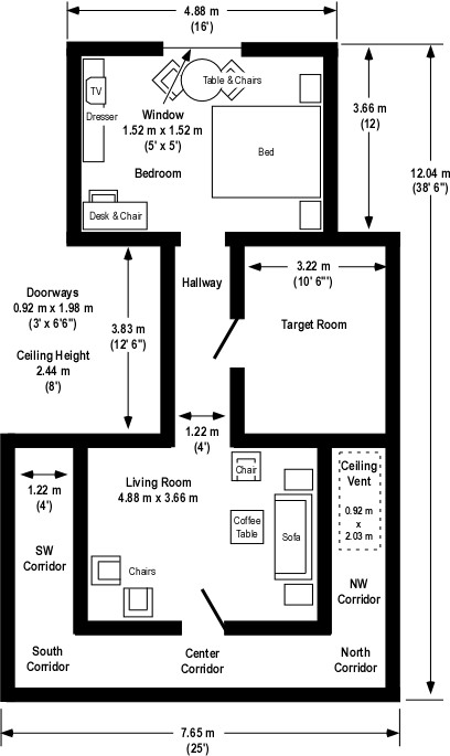
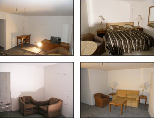
In Wind Driven Fires, I provided an overview of the multi-compartment test structure and fuel load used for this series of experiments. To quickly review, the test structure was comprised of three compartments; Bedroom, Target Room (used to assess tenability in a compartment adjacent to the ventilation flow), and Living Room, along with an interconnecting hallway (between the Bedroom and Living Room) and exterior corridor. Fuel load consisted of typical residential furnishings in the bedroom and living room along with carpet and carpet pad throughout the structure. The target room (used to assess tenability in a potential place of refuge for occupants or firefighters) did not contain any furnishings. Different types of doors (metal, hollow core wood, etc.) were used in the tests to evaluate performance under realistic fire conditions.
Two ventilation openings were provided, a ceiling vent in the Northwest Corridor (providing a flow path from the involved compartment(s) into the corridor) and a window (fitted with glass) in the compartment of origin. During the fire tests, the window failed due to differential heating (of the inner and outer surface of the glass) and was subsequently removed by researchers to provide the full window opening for ventilation.
Figure 1. Isometric Illustration of the Test Structure
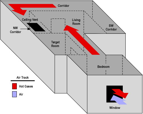
Note: The location of fuel packages in the bedroom and living room is shown on the Floor Plan provided in Wind Driven Fires post.
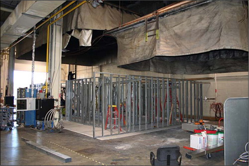
The structure was constructed under a large oxygen consumption calorimetry hood which allowed measurement of heat release rate (once products of combustion began to exit the ceiling vent). In addition, thermocouples, heat flux gages, pressure transducers, and bidirectional probes were used to measure temperature, heat flux, pressure, and gas flow within and out of the structure. Gas sampling probes were located at upper and lower levels, (0.61 m (2′) and 1.83 m (6′) below the ceiling respectively) in the bedroom and living room. Researchers measured oxygen, carbon dioxide, carbon monoxide, and total hydrocarbon concentration during each test.
Experiment 1 Baseline Test
This experiment was different than the others in the series as no external wind was applied to the structure. The fire was ignited in the bedroom and allowed to develop from incipient to fully developed stage in the bedroom.
After 60 seconds the fire had extended from the trash can (first fuel package ignited) to the bed and chair. At this point a visible smoke layer had developed in the bedroom.
120 seconds after ignition, the smoke layer had reached a thickness of 1.2 m (4′) in the bedroom, hallway, and living room. At this point, smoke had just started to enter the corridor. Conditions in the target room were tenable with little smoke infiltration.
At 180 seconds after ignition, the smoke layer was 1.5 m (5′) deep and had extended from the living room into the corridor. Flames from the bed and chair had reached the ceiling. Hot smoke and clear air was well stratified with a distinct boundary between upper and lower layers. Smoke had begun to infiltrate at the top of the door to the target room.
240 seconds after ignition the window started to fail due to flame impingement and the smoke layer extended from ceiling to floor in the bedroom. The smoke layer in the living room had reached a depth of 2.1 m (7′) from the ceiling. Temperature in the corridor remained well stratified.
248 seconds after ignition the researchers cleared the remaining glass from the window to provide a full opening for ventilation. As the glass was removed, the size of the fire in the bedroom and flames exiting the window increased. A thin smoke layer had developed at ceiling level in the target room.
At 300 seconds, flames had begun to burn through the wood, hollow core door to the target room and flaming combustion is also visible in the hallway at the bottom of this door. Flames continued to exit the top 2/3 of the window.
360 seconds into the test, the fire in the bedroom reached steady state (post-flashover), ventilation controlled combustion. The door to the target room has burned through with a dramatic increase in temperature as the room fills with smoke.
Suppression using fixed sprinklers and a hoseline began at 525 seconds.
Fire development during this experiment was not particularly remarkable with conditions that could typically be expected in a residential occupancy. So, what can we learn from this test?
Heat Release Rate
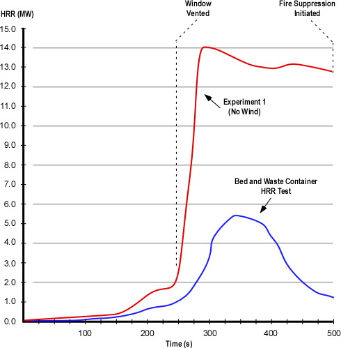
NIST researchers examined the heat release rate of individual fuel packages and combinations of fuel packages prior to the compartment fire tests. These tests conducted in an oxygen consumption calorimeter were performed with the fire in a fuel controlled burning regime. Figure 2 illustrates the heat release rate from the combination of waste container and bed fuel packages and the heat release rate generated during Experiment 1 (in which the initial fuel packages ignited were the waste container and bed located inside the bedroom.
Figure 2. Heat Release Rate Comparison
Note: Adapted from Firefighting Tactics Under Wind Driven Conditions.
Questions: Examine the heat release rate curves in Figure 2 and answer the following questions:
- Why are these two HRR curves different shapes?
- In each of these two cases, what might have influenced the rate of change (increase or decrease in HRR) and peak HRR?
- What observations can you make about conditions inside the test structure and heat release rate (in particular, compare the HRR and conditions at approximately 250 and 350 seconds)?
Temperature
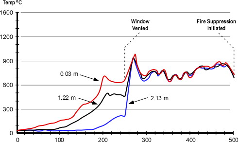
During the experiments temperature was measured in each of the compartments at multiple levels. Figure 3 illustrates temperature conditions in the bedroom at 0.03 m (1″), 1.22 m (4′) and 2.13 m (7′) down from the ceiling during Experiment 1.
Figure 3. Bedroom Temperature
Note: Adapted from Firefighting Tactics Under Wind Driven Conditions. Position.
Questions: Examine the temperature curves in Figure 3 and answer the following questions:
- What can you determine from the temperature curves from ignition until approximately 250 seconds?
- How does temperature change at approximately 250 seconds? Why did this change occur and how does this relate to the data presented in the HRR curve for Experiment 1 (Figure 2)?
- What happens to the temperature at the upper, mid, and lower levels after around 275 seconds? Why does this happen?
Total Hydrocarbons
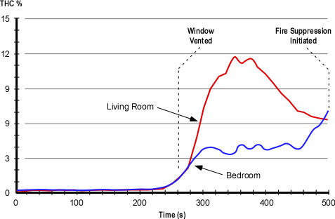
In addition to HRR and temperature, researchers measured gas concentrations inside the compartments at the upper and lower levels. Figure 4 shows the concentration (in % volume) of total hydrocarbons in the bedroom and living room. Concentration of total hydrocarbons is a measure of gas phase fuel (pyrolysis products) in the upper layer.
Figure 4. Total Hydrocarbons at the Upper Level
Note: Adapted from Firefighting Tactics Under Wind Driven Conditions. Position.
Questions: Examine the THC curves in Figure 4 and answer the following questions:
- Why did the THC concentration in the living room rise to a higher level than in the bedroom?
- Why didn’t the gas phase fuel in the living room burn?
- How did the concentration of THC in the bedroom reach approximately 4%? Why wasn’t this gas phase fuel consumed by the fire?
The Story Continues…
My next post will address the answers to these questions (please feel free to post your thoughts) and provide an overview of NIST’s initial tests on the use of wind control devices for anti-ventilation.
Ed Hartin, MS, EFO, MIFireE, CFO


